JETWAY B 860T User manual

1
B 860T
USER'S MANUAL
M/B For Socket 370 Pentium® III Processor
NO. B860T
Release date: March 2002
Trademark:
*Pentium and MMX are trademarks of Intel Corporation.
* All the names and brands are the property of their respective owners.
*Specifications and Information contained in this documentation are furnished for
information use only, are
subject to change at any time without notice, and should not be construed as
a commitment by manufacturer.

2
TABLE OF CONTENT
USER'S NOTICE......................................................................................... ii
MANUAL REVISION INFORMATION.................................................... 1
THERMAL SOLUTIONS............................................................................ 1
CHAPTER 1 INTRODUCTION
1-1 FEATURES OF MOTHERBOARD........................................................... 2
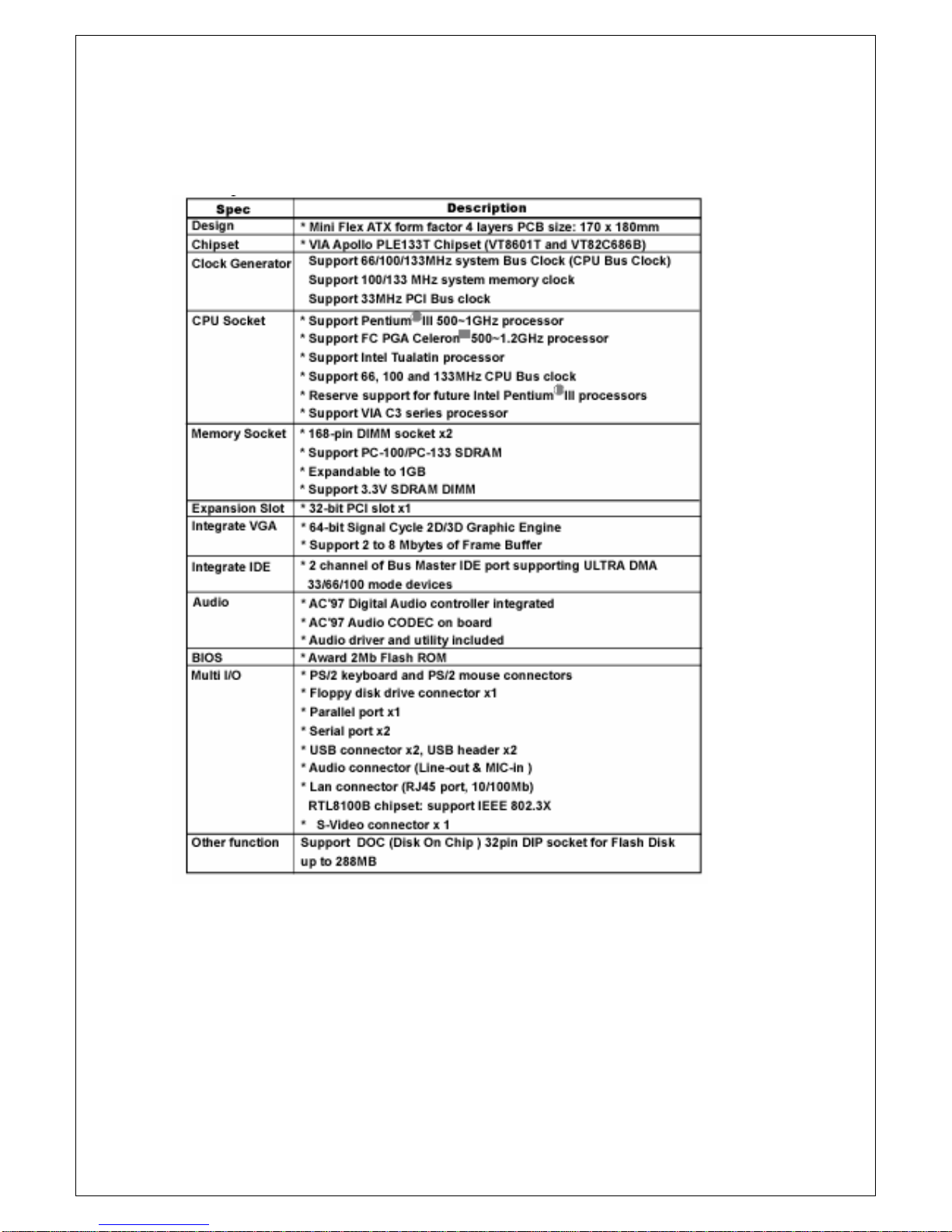
1-2 SPECIFICATION....................................................................................... 3
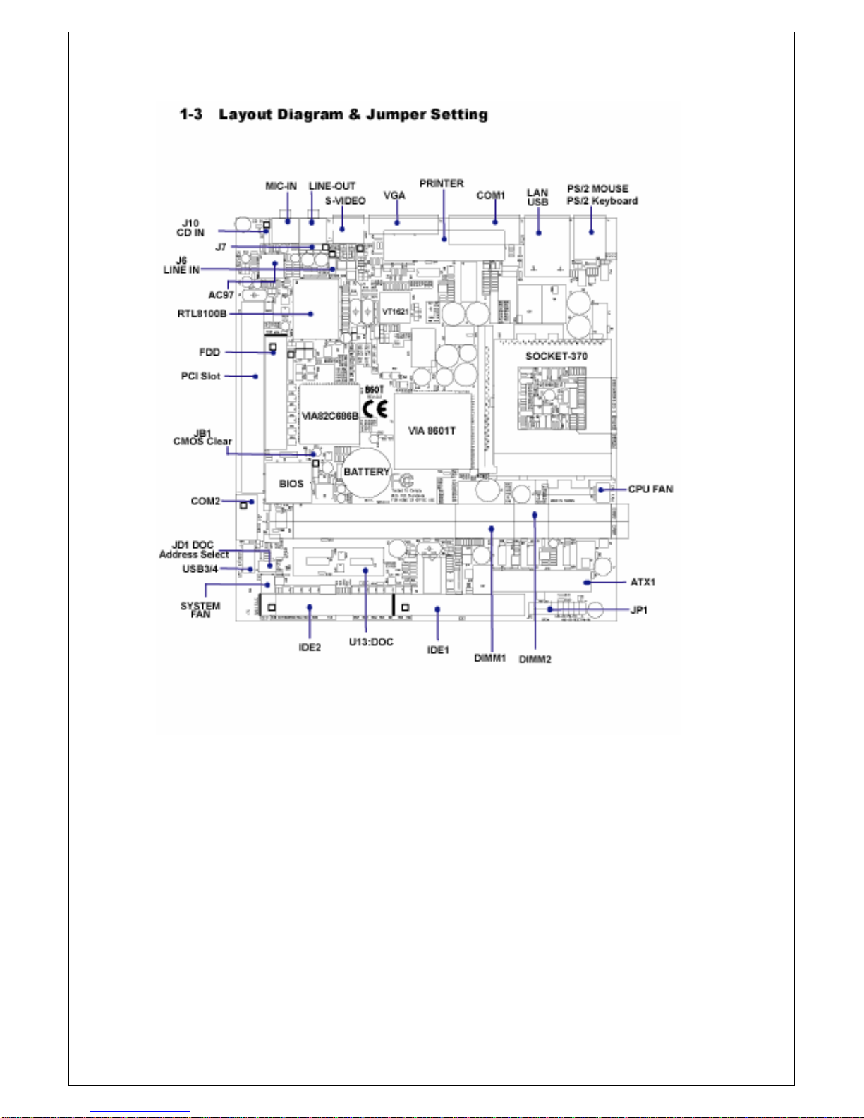
1-3 LAYOUT DIAGRAM & JUMPER SETTING............................................. 4
CHAPTER 2 HARDWARE INSTALLATION
2-1 HARDWARE INSTALLATION STEPS..................................................... 7
2-2 CHECK MOTHERBAORD'S JUMPER SETTING................................... 7
2-3 INSTALL CPU........................................................................................... 8
2-3-1 ABOUTPENTIUM®III&CELERON
TM 370-PIN CPU...............8
2-3-2 INSTALL CPU......................................................................9
2-4 INSTALL MEMORY............................................................................... 9
2-5 EXPANSION CARDS............................................................................... 10
2-5-1 PROCEDURE FOR EXPANSION CARD INSTALLATION..........10
2-5-2 ASSIGN IRQ FOR EXPANSION CARD.......................................11
2-6 CONNECTORS, HEADERS.................................................................... 11
2-6-1 CONNECTORS............................................................................. 11
2-6-2 HEADERS..................................................................................... 14
2-7 START UPYOUR COMPUTER............................................................... 18
CHAPTER 3 INTRODUCTION OF BIOS
3-1 ENTER SETUP......................................................................................... 19
3-2 GET HELP................................................................................................ 20
3-3 THE MAIN MENU..................................................................................... 20
3-4 STANDARD CMOS FEATURES.............................................................. 22
3-5 ADVANCED BIOS FEATURES................................................................ 23
3-6 ADVANCED CHIPSET FEATURES......................................................... 24
3-7 INTEGRATED PERIPHERALS................................................................ 25
3-7-1 ONCHIP IDE FUNCTION...............................................................26
3-8 POWER MANAGEMENT SETUP............................................................ 26
3-8-1 POWER MANAGEMENT................................................................27
3-8-2 WAKE UP EVENTS.........................................................................27
3-8-2.1 IRQS ACTIVITY MONITORING................................................ 28
3-9 PNP/PCI CONFIGURATION SETUP...................................................... 28

3
3-10 PC HEALTH STATUS............................................................................. 29
3-11 FREQUENCY/VOLTAGE CONTROL..................................................... 30
3-12 LOAD STANDARD/OPTIMIZED DEFAULTS........................................ 30
3-13 SET SUPERVISOR/USER PASSWORD............................................... 31
CHAPTER 4 DRIVER & FREE PROGRAM INSTALLATION
MAGIC INSTALL SUPPORTS WINDOWS 95/98/98SE/NT4.0/2000............ 32
4-1 IDE INSTALL VIA IDE/AGPVXD/IRQ ROUTING/INF DRIVER......... 33
4-2 VGA INSTALL VIA 8601 VGA DRIVER.................................................. 35
4-3 SOUND INSTALLALC AUDIO CODEC DRIVER FOR VIA......... 36
4-4 INSTALL LAN DRIVER........................................................................... 37
4-5 PC-HEALTH INSTALLVIA HARDWARE MONITOR DRIVER...... 38
4-5-1 HOW TO USE VIA HARDWARE MONITOR APPLICATION
SOFTWARE.................................................................................38
4-6 MAGIC BIOS INSTALL BIOS LIVE UPDATE UTILITY.......................... 39
4-7 PC-CILLIN INSTALL PC-CILLIN 2000 ANTI-VIRUS PROGRAM… 41
4-8 HOW TO DISABLE ON-BOARD SOUND............................................... 43
4-9 HOW TO UPDATE BIOS......................................................................... 43
USER'S NOTICE
COPYRIGHT OF THIS MANUAL BELONGS TO THE MANUFACTURER. NO
PART OF
THIS MANUAL, INCLUDING THE PRODUCTS AND SOFTWARE DESCRIBED
IN
MAY BE REPRODUCED, TRANSMITTED OR TRANSLATED INTO ANY
LANGUAGE IN
ANY FORM OR BYANY MEANS WITHOUT WRITTEN PERMISSION OF THE
MANUFACTURER.
THIS MANUAL CONTAINS ALL INFORMATION REQUIRED TO USE BN860T
MOTHER-BOARD AND WE DO ASSURE THIS MANUAL MEETS USER'S
REQUIREMENT. BUT IT MAY CHANGE AT ANY TIME WITHOUT NOTICE.
MANUFACTURER PROVIDES THIS MANUAL "AS IS" WITHOUT
WARRANTY OF ANY
KIND, AND WILL NOT BE LIABLE FOR ANY INDIRECT, SPECIAL,
INCIDENTIAL OR
CONSEQUENTIAL DAMAGES (INCLUDING DAMANGES FOR LOSS OF
PROFIT,

4
LOSS OF BUSINESS, LOSS OF USE OF DATA, INTERRUPTION OF
BUSINESS AND THE LIKE).
PRODUCTS AND CORPORATE NAMES IN THIS MANUAL MAY OR MAY
NOT BE REGISTERED TRADEMARKS OR COPYRIGHTS OF THEIR
RESPECTIVE
OWNERS. THEYARE USED ONLY FOR IDENTIFICATION OR EXPLANATION
AND TO THE OWNER'S BENEFIT, WITHOUT INTENT TO INFRINGE.
Item Checklist
5B 860T Motherboard
5Cable for IDE/Floppy
5CD for motherboard utilities
5B 860T User’s Manual
Intel®Processor Family
Thermal Solutions
As processor technology pushes to faster speed and higher performance,
thermal management becomes increasingly crucial to computer systems.
Maintaining the proper thermal environment is the key to reliable, long-term
system operation. The overall goal in providing the proper thermal environment is
keeping the processor's temperature below its specified maximum case temperature.
Heatsinks induce improved processor heat dissipation through increased surface
area and concentrated airflow from attached fans. In addition, interface materials
allow
effective transfers of heat from the processor to the heatsink. For optimum heat
transfer,
Intel recommends the use of thermal grease and mounting clips to attach the heatsink
to the processor. When selecting a thermal solution for your system, please refer to
the website below for collection of heatsinks evaluated and recommended by Intel.
Vendor list for heatsink and fan of Pentium® !!! processor, please visit:
http://developer.intel.com/design/Pentiumiii/components/index.htm
Vendor list for heatsink and fan of Intel® CeleronTM processor, please visit:
http://developer.intel.com/design/celeron/components/index.htm

5
Chapter 1
Introduction
1-1 Features of motherboard
The BN860T is designed for Intel's 370-pin processors and the memory
size is expandable to 1GB (using 256Mb technology). This motherboard is integrated
VGA, Audio, and PC Health Function with Mini Flex ATX form factor and supports
total solution for today's computer and embedded IA market.
This motherboard is based on VIA Apollo PLE133T chipset (VT8601T and
VT82C686B) ,
whose 133MHz front side bus delivers a clear upgrade path to the future generation
of 133MHz processors and PC-100/PC-133 SDRAM. The BN860T motherboard
offers ULTRA DMA 66/100 (ATA 100) to provide higher data transfer rate to HDD
and to boost the overall system performance.
The BN860T also has an integrated AC'97 2.1 CODEC on board which is fully
competitive with Sound Blaster Pro that gives you the best sound quality and
ompatibility. VIA VT8601T chipset also includes integrated 3D Graphic Acceleration
to provide a lower-cost solution for video display.
With USB control as well as capability of expanding to 4 USB devices,
the BN860T meets future USB demand. Moreover, it has built-in hardware
monitor function which can monitor and protect your computer.
This motherboard provides high performance and meets future specification demand.
It is really a wise choice for your application.

6
1-2 Specification

7

8

9
Jumpers
Jumper Name Description Page
JB1 CMOS RAM Clear 3-pin Block p.8
JD1 DOC address select 6-pin Block p.9
Connectors
Connector Name Description Page
ATX1 ATX Power Connector 20-pin Block p.13
J1 PS/2 Mouse & PS/2 Keyboard Connector 6-pin Female p.13
J2 USB Port & LAN RJ45 Connector 16-pin Connector p.14
J4 Parallel Port Connector 25-pin Female p.14
J5 VGA Port Connector 15-pin Female p.14
J3 Serial Port COM1 Connector 9-pin Connector p.14
JACK1 S-Video connector 4-pin Connector p.14
J8 Line out connector Phone jack Connector p.14
J9 MIC-in Connector Phone jack Connector p.14
FDD1 Floppy Driver Connector 34-pin Block p.14
IDE1 Primary IDE Connector 40-pin Block p.15
IDE2 Secondary IDE Connector 40-pin Block p.15
Headers
Header Name Description Page
JC1 COM2 Headers 9-pin Block p.16
JU1 USB 3/4 Port Headers 10-pin Block p.16
PW ON Power on switch 2-pin Block p.17
RESET Reset switch lead 2-pin Block p.16
PWLED Power LED 2-pin /3 pin Block p.16
HDLED IDE activity LED 2-pin Block p.16
LAN LED LAN activity LED 2-pin Block p.16
SPEAK Speaker connector 4-pin Block p.16
JF1, JF3 FAN Speed Headers 3-pin Block p.17
JI1 IR infrared module Headers 5-pin Block p.17
J6 Line in Headers 4-pin Block
J7 Line-out & MIC-in Headers 5-pin Block
J10 CD Audio-In Headers 4-pin Block p.18

10
Expansion Sockets
Socket/Slot Name Description Page
ZIF Socket 370 CPU Socket 370-pin FC-PGA/PPGACPU Socket p.9
DIMM1,DIMM2 DIMM Module Socket 168-pin DIMM Module Socket p.11
PCI1 PCI Slot 32-bit PCI Local Bus Expansion slots p.13
U13 Support DOC(Disk On Chip) flash disk p.17
Chapter 2
Hardware installation
2-1 Hardware installation Steps
Before using your computer, you had better complete the following steps:
1. Check motherboard jumper setting
2. Install CPU and Fan
3. Install System Memory (DIMM)
4. Install Expansion cards
5. Connect IDE and Floppy cables, Front Panel /Back Panel cable
6. Connect ATX Power cable
7. Power-On and Load Standard Default
8. Reboot
9. Install Operating System
10. Install Driver and Utility
2-2 Checking Motherboard’s Jumper Setting
(1) CMOS RAM Clear (3-pin): JB1
A battery must be used to retain the motherboard configuration in CMOS
RAM short pin1 and pin2 of JB1 to store the CMOS data.
To clear the CMOS, follow the procedure below:
1. Turn off the system and unplug the AC power
2. Remove ATX power cable from ATX power connector
3. Locate JB1 and short pin2 and pin2 for a few seconds
4. Return JB1 to its normal setting by shorting pin1 and pin2
5. Connect ATX power cable back to ATX power connector
Note: Do not clear CMOS unless
1. Trouble-shooting
2. You forget the password
3. You fail over-clocking system

11
2-3-2 Install CPU
This motherboard provides a ZIF socket 370.The CPU that comes with the
motherboard
should have a cooling FAN attached to prevent overheating. If this is not the case,
then purchase a correct cooling FAN before you turn on your system.
WARNING!
Be sure that there is sufficient air circulation across the processor's heatsink
and theCPU cooling FAN is working correctly; otherwise, it may cause
overheating and damage the processor and motherboard. You may install
an auxiliary cooling FAN, if necessary.
Before installing a CPU, first of all, turn off your system and remove its cover.
Locate the ZIF socket and open it by pulling the lever sideways up away from
the socket then upward to a 90-degree angle. Insert the CPU with the
correct orientation as shown below.

12
The notched corner should point toward the end of the level.
Because the CPU has a corner pin for two of the four corners, the CPU will
fit only in the orientation as shown.
2-4 Install Memory
This motherboard provides two 168-pin DUAL INLINE MEMORY
MODULES (DIMM) sites for memory expansion from 32MB to 1GB SDRAM.
NOTE!
Make sure the total installed memory size does not exceed 1GB;
otherwise, the system may hang during startup.

13
NOTE!
When you install DIMM module fully into the DIMM socket, the eject tab should be
locked into the DIMM module very firmly and fit into its indention on both sides.
WARNING!
If the SDRAM CLOCK is set at 133MHz, you must use PC133-compliant
DIMMs. When this motherboard operates at 133Mhz, most system will not even
boot if nonPC133-compliant SDRAM modules are used because of
the strict timing issues. If your DIMMs are not PC133-compliant, set the SDRAM
clock at 100MHz to ensure system's stability.
2-5 Expansion Cards
WARNING!
Turn off the power when adding or removing expansion cards or other system
components. Failure to do so may cause severe damage to both your
motherboard and expansion cards.
2-5-1 Procedure For Expansion Card Installation
1. Read the documentation of your expansion card and make any necessary
hardware or software setting, such as jumpers, for your expansion card.
2. Remove the chassis cover and the bracket plate on the slot you intend to use.
3. Align the card with slot and insert the card firmly.
4. Secure the card in the slot with the screen you remove above.
5. Replace the chassis cover.
6. Set up the BIOS if necessary.
7. Install the necessary software driver for your expansion card.
2-5-2 Assign IRQs For Expansion Card
Some expansion cards need an IRQ to operate. Generally, an IRQ must be
exclusively
assigned to one. In a standard design, there are 16 IRQs but most of them are
already in use.
Standard Interrupt Assignments
IRQ Priority Standard function
0 1 System Timer
1 2 Keyboard Controller
2 N/A Programmable Interrupt
3 * 11 Communications Port (COM2)
4 * 12 Communications Port (COM1)
5 * 13 Sound Card (sometimes LPT2)

14
6 14 Floppy Disk Controller
7 * 15 Printer Port (LPT1)
8 3 System CMOS/Real Time Clock
9 * 4 ACPI Mode when enabled
10 * 5 IRQ Holder for PCI Steering
11 * 6 IRQ Holder for PCI Steering
12 * 7 PS/2 Compatible Mouse Port
13 8 Numeric Data Processor
14 * 9 Primary IDE Channel
15 * 10 Secondary IDE Channel
* These IRQs are usually available for ISA or PCI devices.
2-6 Connectors, Headers
2-6-1 Connectors
(1)Power Connector (20-pin block) : ATX1
ATX Power Supply connector. This is a new defined 20-pin connector that
usually comes with ATX case. TheATX Power Supply is allowed to use soft power
on momentary switch that connects from the front panel switch to 2-pin Power
On jumper pole on the motherboard. When the power switch on the back
of the ATX power supply turned on, the full power will not come into the system
board until the front panel switch is momentarily pressed. Press this
switch again will turn off the power to the system board.
(2)PS/2 Mouse & PS/2 Keyboard Connector: J1
If you use a PS/2 mouse, you must purchase an optional PS/2 mouse set
which connects to the 5-pins block and mounts to an open slot on your
chassis.
(3)USB/ LAN Port connector: J2
The connector is a 16-pin connector that connects USB/LAN devices to
the system board.
(4)Parallel Port Connector (25-pin female):J4

15
Parallel Port connector is a 25-pin D-Subminiature Receptacle connector.
The On-board Parallel Port can be disabled through the BIOS SETUP.
Please refer to Chapter 3 "INTEGRATED PERIPHERALS SETUP" section for
more information.
(5)VGA Connector (15-pin female): J5
This connector is for on-board VGA display connection only. If you insert any
external VGA card in PCI slot, you should have the connection to your VGA card's
connector. And you have to set "Init Display First" to PCI under Integrated
Peripherals option in BIOS Setup Utility to get display from PCI VGA card.
(6)S-Video Connector (4-pin female): JACK1
This connector is for on-board TV-OUT connection . If you connect the system to
any external TV device, you will find NTSC/ PAL selection in BIOS Setup.
(7) Audio and Game Connector: J8,J9
Thess connectors are 2 phone Jacks for LINE-OUT, MIC-IN .
Line-out : Audio output to speaker
MIC-IN : Microphone Connector
(8) Serial Port COM1: J3
COM1 is the 9-pin D-Subminiature mail connector. The On-board serial port
can be disabled through BIOS SETUP. Please refer to Chapter 3 "INTEGRATED
PERIPHERALS SETUP" section for more information.
(9)Floppy Drive Connector (34-pin block): FDD1
This connector supports the provided floppy drive ribbon cable. After connecting
the single plug end to motherboard, connect the two plugs at the other end to
the floppy drives.

16
(10)Primary IDE Connector (40-pin block): IDE1
This connector supports the provided IDE hard disk ribbon cable. After
connecting the single plug end to motherboard, connect the two plugs at the other
end to your hard disk(s). If you install two hard disks, you must configure the
second drive to Slave mode by setting its jumpers accordingly. Please refer to the
documentation of your hard disk for the jumper settings.
(11)Secondary IDE Connector (40-pin block): IDE2
This connector connects to the next set of Master and Slave hard disks.
Follow the same procedure described for the primary IDE connector. You may
also configure both two hard disks to Masters mode by using one ribbon cable
on the primary IDE connector and another ribbon cable on the secondary IDE
connector.
.Two hard disks can be connected to each connector. The first HDD is
referred to as the "Master" and the second HDD is referred to as the "Slave".
. .We strongly suggest you not to install a CD-ROM or DVD-ROM drive on the
same IDE channel with a hard disk. Otherwise, the system performance on

17
this channel may drop.
2-6-2 Headers
(1)COM2 Headers (9-pin header) : JC1
This board has another serial port COM2, it comes with the cable providing serial
port COM2.
(2)USB Port Headers (10-pin header): JU1
These headers are used to connect the additional USB port plug.
By attaching an option USB cable, your will get two additional USB plugs
affixed to the back panel.
(3)Front Panel Headers (2x9-pin header): JP1
1. Power switch: PW-ON
This 2-pin connector connects to the case-mounted power switch to power
on/ off the system.
2. Reset switch lead: RESET
This 2-pin connector connects to the case-mounted reset switch for rebooting
your computer without turning off your power switch. This is a preferred
way to restart the system.
3. Power LED: PW-LED
The Power LED is lit while the system power is on. Connect the Power LED
from the system case to this 2/ 3-pin connector.
4. IDE Activity LED: HDD-LED
HDD-LED shows the activity of the hard.
5. LAN LED Activity LED: LAN- LED

18
LAN-LED shows the activity of network. (If the case have the LED
function).
6. Speaker connector: SPEAK
This 4-pin connector connects to the case-mounted speaker.
Seethefigurebelow.
(4)FAN Speed Headers (3-pin) : JF1, JF3
These connectors support cooling fans of 350mA (4.2 Watts) or less, depending
on the fan manufacturer. The red wire should be positive, while the black one
should be ground. Connect the fan's plug to the board according to the polarity
of connector.
(5)IR infrared module Headers (10-pin) : JI1
This connector supports the optional wireless transmitting and receiving infrared
module. To use the IR function, you must configure the setting through the
BIOS setup.

19
(6)CD Audio-In Headers (4-pin) : J10
This header is for the CD-ROM Audio connector.
(7)Line-in Headers (4-pin) : J6
This header is for Line-in connector.
(8)Audio-In/Out Headers (5-pin) : J7
The Audio-in header is for MIC-in connector.
The Audio-out header is for Line-out connector.

20
(9)DOC socket : U13,JD1
DOC 32pin dip socket can support flash disk up to 288MB
DOC address can select among three address: D000-D1FFh ,
D800-D9FFh,DE00- DFFFh.
2-7 Start Up Your Computer
1. After all the connections are made, close the chassis cover.
2. Be sure all the switches are off and check if the power supply input voltage is
set at the proper position. Usually the in-put voltage is 220V~240V or
110V~120V, depending the country.
3. Connect the power supply cord into the power supply located on the back of
your system case according to the user's manual of your system.
4. Turn on your peripherals as the following orders:
a. Your monitor.
b. Other external peripherals (Printer, Scanner, External Modem etc...)
c. Your system power. For ATX power supplies, you need to turn on the
power supply and press theATX power switch which is on the front panel
of the case.
5. The power LED on the front panel of the system case will be lit. The LED on
the monitor may be lit or switch between orange and green colors after the
system is on. If it complies with green standards or if it has the power stand-by
feature, the system will run the Power-on test. While the tests are running,
the BIOS will alarm beeps or additional message will appear on the screen.
Table of contents
Other JETWAY Motherboard manuals

JETWAY
JETWAY PM2M User manual

JETWAY
JETWAY JNP891 Series User manual

JETWAY
JETWAY BX2000 User manual

JETWAY
JETWAY NU792V User manual

JETWAY
JETWAY NF93 Series User manual

JETWAY
JETWAY NF796M-H310 Series User manual

JETWAY
JETWAY I405R4A User manual

JETWAY
JETWAY NF9T Series User manual

JETWAY
JETWAY G03-NC9T-F User manual

JETWAY
JETWAY V266BR4A User manual

JETWAY
JETWAY V333DAR2A User manual

JETWAY
JETWAY 601CFR1C User manual

JETWAY
JETWAY 623DM User manual

JETWAY
JETWAY NF9HB Series User manual

JETWAY
JETWAY 848PDCR2A User manual

JETWAY
JETWAY 601CFR4A User manual

JETWAY
JETWAY 845GLM User manual

JETWAY
JETWAY MI92 User manual

JETWAY
JETWAY S450R2A User manual

JETWAY
JETWAY N2PA-LITE User manual