JETWAY LA0H Series User manual

LA0H Series
User’s Manual
No. G03-LA0H-F
Rev: 2.0
Release date: November 18, 2021
Trademark:
* Specifications and Information contained in this documentation are furnished for information use only, and are
subject to change at any time without notice, and should not be construed as a commitment by manufacturer.

ii
ENVIRONMENTAL SAFETY INSTRUCTION................................................................................... iii
ENVIRONMENTAL PROTECTION ANNOUCEMENT.................................................................... iii
USER’S NOTICE.................................................................................................................................... iv
MANUAL REVISION INFORMATION................................................................................................ iv
ITEM CHECKLIST..................................................................................................................................iv
CHAPTER 1 INTRODUCTION OF THE MOTHERBOARD
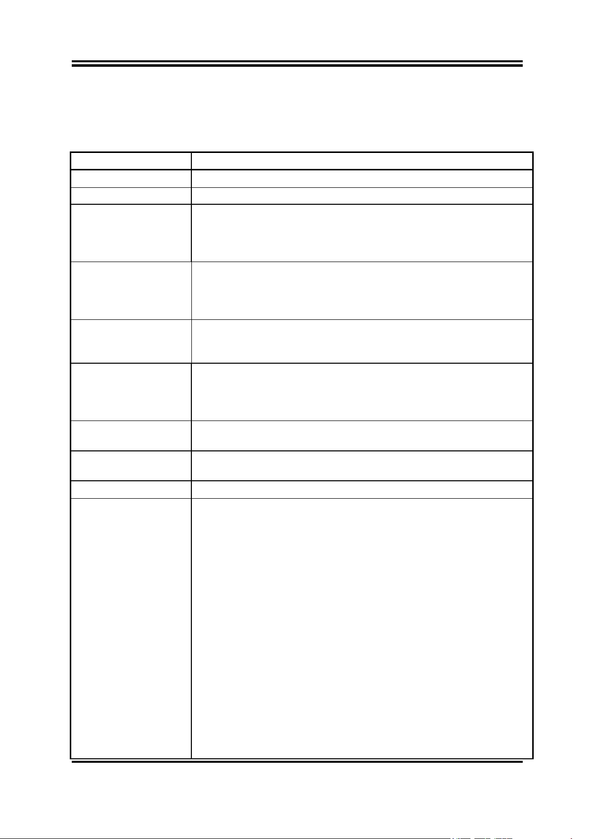
1-1 SPECIFICATION.................................................................................................................... 1
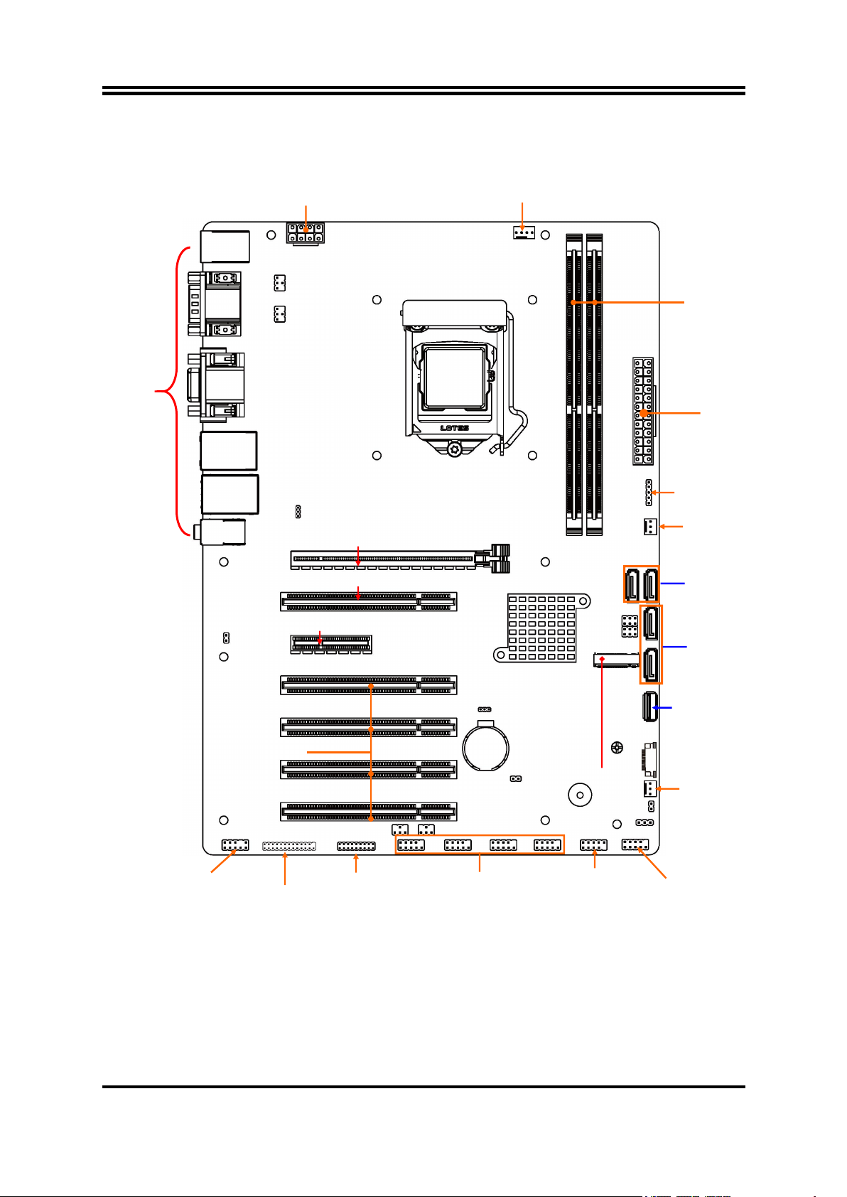
1-2 LAYOUT DIAGRAM...............................................................................................................2
CHAPTER 2 HARDWARE INSTALLATION
2-1 JUMPER SETTINGS..............................................................................................................6
2-2 CONNECTORS AND HEADERS........................................................................................ 9
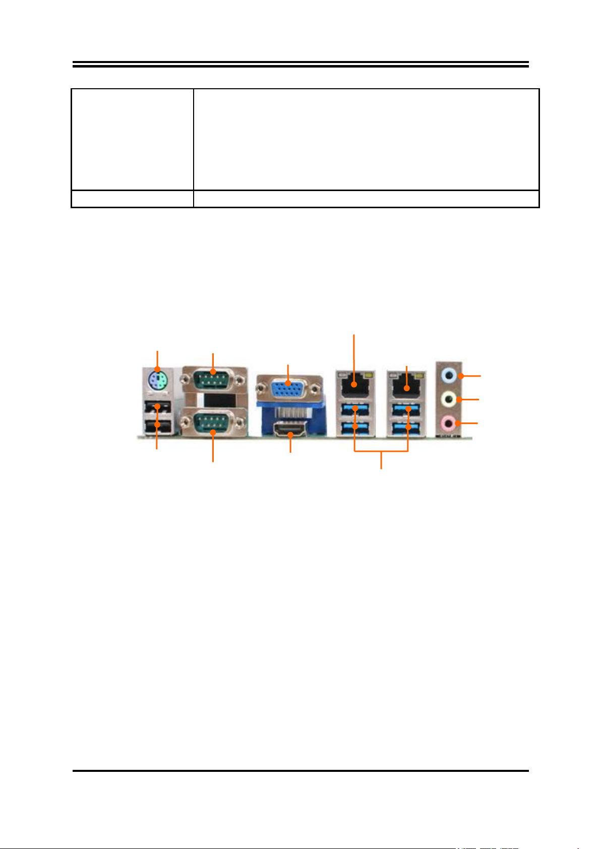
2-2-1 REAR I/O BACK PANEL CONNECTORS......................................................... 9
2-2-2 MOTHERBOARD INTERNAL CONNECTORS................................................. 10
2-2-3 HEADER PIN DEFINITION....................................................................................13
2-2-4 MAXIMUM VOLTAGE & CURRENT LIMIT........................................................16
CHAPTER 3 INTRODUCING BIOS
3-1 ENTERNING SETUP............................................................................................................. 17
3-2 BIOS MENU SCREEN...........................................................................................................18
3-3 FUNCTION KEYS...................................................................................................................18
3-4 GETTING HELP......................................................................................................................18
3-5 MENU BARS........................................................................................................................... 19
3-6 MAIN MENU............................................................................................................................ 19
3-7 ADVANCED MENU................................................................................................................20
3-8 CHIPSET MENU..................................................................................................................... 29
3-9 BOOT MENU...........................................................................................................................31
3-10 SECURITY MENU.................................................................................................................. 33
3-11 SAVE & EXIT MENU..............................................................................................................34
TABLE OF CONTENT

iii
Environmental Safety Instruction
Avoid the dusty, humidity and temperature extremes. Do not place the product in
any area where it may become wet.
0 to 40 centigrade is the suitable temperature. (The figure comes from the request
of the main chipset)
Generally speaking, dramatic changes in temperature may lead to contact
malfunction and crackles due to constant thermal expansion and contraction from
the welding spots’ that connect components and PCB. Computer should go
through an adaptive phase before it boots when it is moved from a cold
environment to a warmer one to avoid condensation phenomenon. These water
drops attached on PCB or the surface of the components can bring about
phenomena as minor as computer instability resulted from corrosion and oxidation
from components and PCB or as major as short circuit that can burn the
components. Suggest starting the computer until the temperature goes up.
The increasing temperature of the capacitor may decrease the life of computer.
Using the close case may decrease the life of other device because the higher
temperature in the inner of the case.
Attention to the heat sink when you over-clocking. The higher temperature may
decrease the life of the device and burned the capacitor.
Environmental Protection Announcement
Do not dispose this electronic device into the trash while discarding. To minimize
pollution and ensure environment protection of mother earth, please recycle.

iv
USER’S NOTICE
COPYRIGHT OF THIS MANUAL BELONGS TO THE MANUFACTURER. NO PART OF THIS MANUAL,
INCLUDING THE PRODUCTS AND SOFTWARE DESCRIBED IN IT MAY BE REPRODUCED, TRANSMITTED
OR TRANSLATED INTO ANY LANGUAGE IN ANY FORM OR BY ANY MEANS WITHOUT WRITTEN
PERMISSION OF THE MANUFACTURER.
THIS MANUAL CONTAINS ALL INFORMATION REQUIRED TO USE THIS MOTHER-BOARD SERIES AND WE
DO ASSURE THIS MANUAL MEETS USER’S REQUIREMENT BUT WILL CHANGE, CORRECT ANY TIME
WITHOUT NOTICE. MANUFACTURER PROVIDES THIS MANUAL “AS IS” WITHOUT WARRANTY OF ANY
KIND, AND WILL NOT BE LIABLE FOR ANY INDIRECT, SPECIAL, INCIDENTAL OR CONSEQUENTIAL
DAMAGES (INCLUDING DAMAGES FOR LOSS OF PROFIT, LOSS OF BUSINESS, LOSS OF USE OF DATA,
INTERRUPTION OF BUSINESS AND THE LIKE).
PRODUCTS AND CORPORATE NAMES APPEARING IN THIS MANUAL MAY OR MAY NOT BE
REGISTERED TRADEMARKS OR COPYRIGHTS OF THEIR RESPECTIVE COMPANIES, AND THEY ARE
USED ONLY FOR IDENTIFICATION OR EXPLANATION AND TO THE OWNER’S BENEFIT, WITHOUT
INTENT TO INFRINGE.
Manual Revision Information
Reversion Revision History Date
2.0 Second Edition November 18, 2021
Item Checklist
Motherboard
Cable(s)
I/O Back panel shield

1
Chapter 1
Introduction of the Motherboard
1-1 Specification
Spec
Description
Design
ATX form factor; PCB size: 30.5 x22 cm
Chipset
Intel H410 Express Chipset
CPU Socket
Intel LGA 1200 Socket supports 10th Comet Lake-S
processors (Max.100W TDP)
*Note:for detailed CPU support information please visit our
website
Memory Slots
2*DDR4 long DIMM DRAM module slot
Supporting 2* 2666MHz DDR4 DRAM Module,
expandable to 64 GB (Maximum)
Support dual-channel function
Expansion Slots
1 * PCI-Express x16 slot (PCIEX16)
1 * PCI-Express x4 slot (*PCIEX4)
5 * PCI slot (PCI1/2/3/4/5)
Storage
4 * SATAIII 6Gb/s port (SATA1/2/3/4,SATA4 selectable
with M2 Slot))
1* M.2 M-key slot,type-2242/2280 with SATA interface
(M2,selectable with SATA4)
LAN Chip
1* Intel i219LM GbE LAN chip & 1* Intel i225LM 2.5GbE
LAN chip
Audio Chip
Realtek HD Audio Codec integrated with Audio driver and
utility included
BIOS
AMI 128M Flash ROM
Multi I/O
Rear Panel I/O:
1* PS/2 keyboard & mouse combo port connector
2* USB 2.0 port connector
2*Serial port connector(COM1-1, support RS232/422/485
function)
1* VGA port connector
1* HDMI port connector
4* USB 3.1 (Gen.1) port connector
1* 2.5GbE RJ-45 LAN port
1* 1GbE RJ-45 LAN port
1* 3-phone audio jack
Internal I/O Connectors, Wafer & Headers:
1 *24-pin main power connector
1 *8-pin 12V power connector
1* CPUFAN connector & 2* SYSFAN connector
1* internal Erect type USB 2.0 port connector
1* Front panel header
1* 9-Pin USB 2.0 header for 2* expansion USB 2.0 ports

2
4* RS232 Serial port header (COM3/4/5/6)
1* GPIO header (*GPIO: Co-lay with LPT, optional by
order)
1* Parallel header(*LPT: Co-lay with GPIO, optional by
order)
1* Front panel audio header
1* SMBUS header
TPM 2.0 Function
Optional for LA0H-02 Series
*Note: LA0H-00 and LA0H-02 series are basically the same in specifications & layout,
except that LA0H-02 supports TPM 2.0 function.
1-2 Layout Diagram
Rear IO Diagram
*Note:Many PCs now include XHCI USB controllers which allow for the support of USB 3.0(or higher
version) and higher USB speeds. This inclusion of XHCI controllers has lessened the need for EHCI
USB controllers within platforms. However, legacy operating systems (OS) may not natively recognize
XHCI controllers. You might need to pre-install XHCI driver while desiring to install a non-XHCI OS
(ex.Windows* 7) on Intel platforms which do not include EHCI controllers. Please contact your
representative for more details.
PS/2
KB & MS
Combo Port
COM1
RS232/422/485
Serial Port
USB 2.0 Ports
COM2
RS232/422/485
Serial Port
VGA Port
HDMI Port
USB 3.2 (Gen.1) Ports
Line-IN
Line-OUT
MIC-IN
UL2:RJ-45 LAN Port
(2.5GbE)
UL1:RJ-45 LAN Port
(1GbE)

3
Motherboard Internal Diagram
*Note: SATA4 port co-lays with M2 slot; these two interfaces cannot function at the same time, user
can choose one of them to work via JP7 &JP6 jumper settings.
*Rear IO
Connector
(Refer to Page-2)
ATX 12V
Power Connector
CPUFAN
Connector
DDR4
DIMM Slot x 2
ATX Power
Connector
SMBUS Header
Internal Vertical
USB 2.0 Port
USB 2.0 Port
Header
Front Panel
Header
SATAIII Ports
(SATA1/SATA2)
SATAIII Ports
(*SATA4/SATA3)
Serial Port Headers
(COM3/4/5/6)
16-bit GPIO
Header
(*Optional)
Parallel Port
Header
(*Optional)
Front Panel
Audio Header
PCI Slots(PCI2/3/4/5)
PCI Express x4 Slot (PCIEX4)
PCI Express x16 Slot (PCIEX16)
PCI Slot(PCI1)
SYSFAN1
Connector
SYSFAN2
Connector
*M.2 M-Key Slot
(M2)

4
Motherboard Jumper Positions
Jumper
Jumper
Name
Description
Pitch
JCOM1
COM1 Port Pin9 Function Select
4-pin Block
2.0mm
JCOM2
COM2 Port Pin9 Function Select
4-pin Block
2.0mm
JCOM3
COM3 Header Pin9 Function Select
4-pin Block
2.0mm
JCOM4
COM4 Header Pin9 Function Select
4-pin Block
2.0mm
JP8
Rear Panel UL1 USB Ports VCC Select
3-pin Block
2.0mm
JBAT
CMOS RAM Clear Function Setting
3-pin Block
2.0mm
COPEN
Case Open Message Display Detect
2-pin Block
2.54mm
AT_ATX
ATX/AT Mode Select
3-pin Block
2.0mm
JP7&JP6
SATA4/M2 Slot Function Select
6-pin Block
2.0mm
JCOM1
JCOM2
JP7
JP6
AT_ATX
COPEN
JBAT
JP8
JCOM3
JCOM4

5
Connectors
P/N
Name
PS2_USB1
Top: PS/2 Keyboard & Mouse Combo Port
Middle & Bottom: USB 2.0 Connector X2
COM1_1
RS232/422/485 Serial Port Connector
HDMI
High-Definition Multimedia Interface Connector
VGA
VGA Port Connector
UL2
Top: 2.5GbE RJ-45 LAN Connector
Middle & Bottom: USB 3.2 Gen.1 Port Connector X2
UL1
Top: 1GbE RJ-45 LAN Connector
Middle & Bottom: USB 3.2 Gen.1 Port Connector X2
AUDIO
Top: Line-in Connector
Middle: Line-out Connector
Bottom: MIC Connector
ATXPWR
ATX Main Power Connector
ATX12V
ATX 12V Power Connector
SYSFAN1/SYSFAN2/
CPUFAN
FAN Connector X3
SATA1/2/3/4
SATAIII Connector X4
FP_USB2
USB 2.0 Port Connector (Internal Erect type)
Headers
P/N
Name
Description
Pitch
JW_FP
(Front Panel Header)
PWR LED/ HD LED/ Power
Button /Reset
9-pin Block
2.54mm
FP_USB1
USB 2.0 Header
9-pin Block
2.54mm
COM3/4/5/6
RS232 Serial Port Wafer
9-pin Block
2.54mm
*GPIO_CON(by order)
GPIO Header
18-pin Block
2.0mm
*PARALLEL1(by order)
Parallel Port Header
25-pin Block
2.0mm
FP_AUDIO (Optional)
Front Panel Audio Header
9-pin Block
2.54mm
SMBUS
SMBUS Header
5-pin Block
2.0mm
*Note: The default board comes with GPIO_CON header. PARALLEL1 header is only optional by
order and only one of them comes with a board. Please refer to the product you purchase for actual
specification.

6
Chapter 2
Hardware Installation
2-1 Jumper Settings
JCOM1 (4-pin): COM1 Port Pin9 Function Select
JCOM1
→
COM1 Port Pin-9
1
3
5
4
6
2
1
3
5
6
4
2
1
3
5
6
4
2
2-4 Closed:
RI=RS232;
3-4 Closed:
RI= 5V;
4-6 Closed:
RI= 12V;
JCOM2 (4-pin): COM2 Port Pin9 Function Select
JCOM2
→
COM2 Port Pin-9
1
3
5
4
6
2
1
3
5
6
4
2
1
3
5
6
4
2
2-4 Closed:
RI=RS232;
3-4 Closed:
RI= 5V;
4-6 Closed:
RI= 12V;
JCOM3 (4-pin): COM3 Header Pin9 Function Select
JCOM3
→
COM3 Header Pin-9
4-6 Closed:
RI= 12V.
1
3
5
3-4 Closed:
RI= 5V;
2-4 Closed:
RI=RS232;
4
6
2
1
3
5
4
2
6
2
4
6
1
3
5
JCOM4 (4-pin): COM4 Header Pin9 Function Select
JCOM4
→
COM4 Header Pin-9
4-6 Closed:
RI= 12V.
1
3
5
3-4 Closed:
RI= 5V;
2-4 Closed:
RI=RS232;
4
6
2
1
3
5
4
2
6
2
4
6
1
3
5
JCOM1
JCOM2
COM3
JCOM3
COM4
JCOM4

7
JP8 (3-pin): Rear Panel UL1 USB Ports VCC Select
2-3 Closed: VCC.
1-2 Open: 5VSB;
1
3
1
3
JP8
→
UL1 USB Ports VCC Select
JBAT (3-pin): Clear CMOS RAM Settings
2-3 Closed: Clear CMOS.
1-2 Open: Normal;
1
3
1
3
JBAT
→
Clear CMOS Settings
COPEN (2-pin): Case Open Message Display Function Select
Pin1
COPEN
→
Case Open Detection
CASE OPEN
GND
Pin 1-2 Short:When Case open function pin short to GND, the Case open function was
detected. When Used, needs to enter BIOS and enable ‘Case Open Detect’function. In this
case if your case is removed, next time when you restart your computer, a message will be
displayed on screen to inform you of this.
COPEN
JP8
UL1
JBAT

8
AT_ATX (3-pin): ATX Mode/AT Mode Select
*ATX Mode Selected: Press power button to power on after power input ready;
AT Mode Selected: Directly power on as power input ready.
Combination block of JP7 & JP6 (6-pin): SATA4 Port/M2 Slot Function Select
JP7 & JP6
→
SATA4/M2 Slot Select
JP7 & JP6 (1-3) & (2-4) Closed:
M2 Slot Selected.
5
3
6
4
JP7
→
2
1
4
6
2
5
3
1
JP7 & JP6 (3-5) & (4-6) Closed:
SATA4 Port Selected.
JP7
→
5
3
6
4
2
1
&
3
5
4
6
2
1
JP6
→
JP6
→
&
AT_ATX
*M.2 M-Key Slot
(M2)
SATA4
JP6
JP7

9
2-2 Connectors and Headers
2-2-1 Rear I/O Back Panel Connectors
Icon
Name
Function
PS/2 Mouse
& Keyboard
Combo Port
This combo port is for user to connect PS/2 mouse
or keyboard device to the board.
USB 2.0 Port
To connect USB keyboard, mouse or other
devices compatible with USB specification.
RS232/422/485
Serial Port
Mainly for user to connect external MODEM or
other devices that supports
Serial Communications Interface.
VGA Port
To connect display device that support VGA
specification.
(Max Resolution: 1920×1200@60Hz)
HDMI Port
To connect display device that support HDMI
specification.
(Max Resolution: 4096×2304@24Hz)
USB 3.2 (Gen.1) Port
To connect USB keyboard, mouse or other
devices compatible with USB specification. USB
3.2 (Gen.1) port supports up to 5Gbps data
transfer rate.
RJ-45 LAN Port
This connector is standard RJ-45 LAN jack for
Network connection (UL1 Intel®i219-LM PHY LAN
port supports up to 1.0 Gbps transfer rate; UL2
from Intel®i225-LM supports up to 2.5Gbps
transfer rate).
Audio Connectors
BLUE: Line-in Connector
GREEN:Line-out Connector
PINK : MIC Connector
PS/2
KB & MS
Combo Port
COM1
RS232/422/485
Serial Port
USB 2.0 Ports
COM2
RS232/422/485
Serial Port
VGA Port
HDMI Port
USB 3.2 (Gen.1) Ports
Line-IN
Line-OUT
MIC-IN
UL2: RJ-45 LAN Port
(2.5GbE)
UL1:RJ-45 LAN Port
(1GbE)

10
COM1-1: COM1 & COM2 RS232/422/485 Port
COM1 & COM2 ports can function as RS232/422/485 port. In normal settings
COM1/COM2 functions as RS232 port. With compatible COM cable they can function
as RS422 or RS 485 port.
User also needs to go to BIOS to set ‘Transmission Mode Select’for COM1/COM2
(refer to Page-23) at first, before using specialized cable to connect different pins of
this port.
The pin assignment for RS-232/ 422/ 485 is listed as follows:
1
2
3
4
5
6
7
8
9
RS232 DCD#
RS232 SIN
RS232 SOUT
RS232 DTR#
GND
RS232 RI#
RS232 CTS#
RS232 RTS#
RS232 DSR#
RS232 Mode
RS422 Mode
RS485 Mode
Pin1
GND
RS422 RX(B)
RS422 RX(A)
RS422 TX(A)
RS422 TX(B)
Pin1
GND
RS485 D+(A)
RS485 D-(B)
Pin1
2-2-2 Motherboard Internal Connectors
(1) ATXPWR (24-pin block): Main Power Connector
ATX Power Supply connector: This is a new defined 24-pins connector that
usually comes with ATX case. The ATX Power Supply allows using soft power
on momentary switch that connect from the front panel switch to 2-pins Power
On jumper pole on the motherboard. When the power switch on the back of the
ATX power supply turned on, the full power will not come into the system board
until the front panel switch is momentarily pressed. Press this switch again will
turn off the power to the system board.
** We recommend that you use an ATX 12V Specification 2.0-compliant power
supply unit (PSU) with a minimum of 350W power rating. This type has 24-pin
and 4-pin power plugs.
** If you intend to use a PSU with 20-pin and 4-pin power plugs, make sure that the
20-pin power plug can provide at least 15A on +12V and the power supply unit
has a minimum power rating of 350W. The system may become unstable or may
not boot up if the power is inadequate.
** If you are using a 20-pin power plug, please refer to Figure1 for power supply
connection. Power plug form power supply and power connectors from
motherboard both adopt key design to avoid mistake installation. You can insert
the power plug into the connector with ease only in the right direction. If the
direction is wrong it is hard to fit in and if you make the connection by force if is
possible.

11
PIN
ROW1
ROW2
12
+3.3V
GND
11
+12V
+5V
10
+12V
+5V
9
+5V Stand by
+5V
8
Power OK
-5V
7
GND
GND
6
+5V
GND
5
GND
GND
4
+5V
Soft Power on
3
GND
GND
2
+3.3V
-12V
1
+3.3V
+3.3V
24-pin Main Power Connector
Figure1:20-pin power plug Figure 2:24-pin power plug
(2) ATX12V (8-pin block): ATX12V Type Power Connector
This is a new defined 8-pin connector that usually comes with ATX Power Supply that
supports extra 12V voltage to maintain system power consumption. Without this
connector might cause system unstable because the power supply can not provide
sufficient current for system.
Pin1
4
5
8
Pin No.
4
3
2
1
Definition
GND
GND
GND
GND
Pin No.
8
7
6
5
Definition
+12V
+12V
+12V
+12V

12
(3) CPUFAN(4-pin): CPUFAN Connector
CPUFAN
Fan Speed
GND
Pin1
+12V Fan Power
Control
(4) SYSFAN1/SYSFAN2(3-pin): System Fan Connector
Fan Speed
GND
Pin1
+12V Fan Power
SYSFAN1/SYSFAN2
(5) SATA1/2/3/4: SATAIII Port Connector
These connectors are high-speed SATAIII ports that support 6GB/s transfer rate.
Pin No.
Definition
1
GND
2
TXP
3
TXN
4
GND
5
RXN
6
RXP
7
GND
*Note:The board co-lays SATA4 and M2 slot which are selectable with JP7 & JP6
jumper settings; i.e., only one interface can function at a time.
CPUFAN
SYSFAN1
SYSFAN2
*SATA4
*M.2 M-Key Slot
(M2)
JP6
JP7
SATA3
SATA1
SATA2

13
2-2-3 Header Pin Definition
(1) JW_FP (9-pin): Front Panel Header
(2) FP_USB1(9-pin): USB 2.0 Port Header
(3) COM3/4/5/6 (9-Pin): RS232 Serial Port Header
DCD
Pin1
Pin6
Pin5
SIN
SOUT
DTR
GND
DSR
RTS
CTS
RI
COM5
JW_FP
FP_USB1
COM6
COM4
COM3

14
(4) *GPIO_CON(18-pin): 16-Bit GPIO Header
GPIO70
Pin1
2
GPIO72
GPIO74
GPIO76
GND
GPIO71
GPIO73
GPIO75
GPIO77
VCC
GPIO80
GPIO82
GPIO84
GPIO86
GPIO81
GPIO83
GPIO85
GPIO87
*Note: The default board comes with GPIO_CON header. PARALLEL1 is only optional by order and
only one of them comes with a board. Please refer to the product you purchase for actual specification.
(5) *PARALLEL1(25-pin): Parallel Port Header
Pin1
PARALLEL1: Parallel Header
Pin14
Pin NO.
Pin Definition
Pin NO.
Pin Definition
Pin 1
STB-
Pin 14
AFD-
Pin 2
PD0
Pin 15
ERR-
Pin 3
PD1
Pin 16
INIT-
Pin 4
PD2
Pin 17
SLIN-
Pin 5
PD3
Pin 18
GND
Pin 6
PD4
Pin 19
GND
Pin 7
PD5
Pin 20
GND
Pin 8
PD6
Pin 21
GND
Pin 9
PD7
Pin 22
GND
Pin 10
ACK-
Pin 23
GND
Pin 11
BUSY
Pin 24
GND
Pin 12
PE
Pin 25
GND
Pin 13
SLCT
Pin 26
No Key
*Note: The default board comes with GPIO_CON header. PARALLEL1 header is only optional by
order and only one of them comes with a board. Please refer to the product you purchase for actual
specification.
*PARALLEL1(Optional with GPIO_CON by order)
*GPIO_CON
(Optional with PARRALLEL1 by order)

15
(6) FP_AUDIO (9-pin): Line-Out, MIC-In Header
This header is connected to Front Panel Line-out, MIC connector with cable.
Pin 1
MIC2-L
LINE OUT2-L
MIC2-R
LINE OUT2-R
NC
GND
NC
NC
NC
2
(7) SMBUS (4-pin): SM BUS Header
FP_AUDIO
SMBUS

16
2-2-4 Maximum Voltage & Current Limit
Below is a list of maximum voltage & Current Limit specification for motherboard
interface (including but not limited to slots, connectors and headers) for setup
reference:
Parts
Working Voltage
Current Support
USB Ports
from
PS2_USB1
5V
1.5A
UL1
5V
1.5A
UL2
5V
1.5A
FP_USB2
5V
1.5A
FP_USB1
5V
1.5A
COM1(JCOM1)
5V/12V
0.5A
COM2(JCOM2)
5V/12V
0.5A
COM3(JCOM3)
5V/12V
0.5A
COM4(JCOM4)
5V/12V
0.5A
JW_FP
5V
1A
GPIO_CON (by order)
3V or 5V
(via resistor setting)
1A
SMBUS
5V
0.5A
CPUFAN
12V
1.5A
SYSFAN1
12V
1.5A
SYSFAN2
12V
1.5A
M2
3.3V
2A
Table of contents
Other JETWAY Motherboard manuals

JETWAY
JETWAY S445R1A User manual

JETWAY
JETWAY NMF691 Series User manual

JETWAY
JETWAY NF9U-F User manual

JETWAY
JETWAY 865GDA User manual

JETWAY
JETWAY NF894 Series User manual

JETWAY
JETWAY NF731 User manual

JETWAY
JETWAY NF795-Q170 User manual

JETWAY
JETWAY 625EMWR1A User manual

JETWAY
JETWAY MF13 User manual

JETWAY
JETWAY 754TURBOR208 User manual

JETWAY
JETWAY 845GVFC User manual

JETWAY
JETWAY V600DA User manual

JETWAY
JETWAY G03-NF796-F User manual

JETWAY
JETWAY V6DP User manual

JETWAY
JETWAY HBJC501F797-Q37-B User manual

JETWAY
JETWAY NF796M-H310 Series User manual

JETWAY
JETWAY 693AS User manual

JETWAY
JETWAY 845GDAR1A User manual

JETWAY
JETWAY A76M Series User manual

JETWAY
JETWAY S447R1C User manual