JETWAY G03-TI70MG-F User manual

USER'S MANUAL
Of
Intel NM70 Express Chipset
& Intel Celeron 847 Dual Core
Processor
Based Motherboard
Trademark:
* Specifications and Information contained in this documentation are furnished for information use only, and are
subject to change at any time without notice, and should not be construed as a commitment by manufacturer.
G03-TI70MG-F
Rev: 1.0
Release date: January 30, 2013

i
Environmental Safety Instruction
zAvoid the dusty, humidity and temperature extremes. Do not place the product in any
area where it may become wet.
z0 to 40 centigrade is the suitable temperature. (The figure comes from the request of
the main chipset)
zGenerally speaking, dramatic changes in temperature may lead to contact malfunction
and crackles due to constant thermal expansion and contraction from the welding
spots’ that connect components and PCB. Computer should go through an adaptive
phase before it boots when it is moved from a cold environment to a warmer one to
avoid condensation phenomenon. These water drops attached on PCB or the surface
of the components can bring about phenomena as minor as computer instability
resulted from corrosion and oxidation from components and PCB or as major as short
circuit that can burn the components. Suggest starting the computer until the
temperature goes up.
zThe increasing temperature of the capacitor may decrease the life of computer. Using
the close case may decrease the life of other device because the higher temperature in
the inner of the case.
zAttention to the heat sink when you over-clocking. The higher temperature may
decrease the life of the device and burned the capacitor.
Environmental Protection Announcement
Do not dispose this electronic device into the trash while discarding. To minimize pollution
and ensure environment protection of mother earth, please recycle.

ii
CHAPTER 1 INTRODUCTION OF MOTHERBOARD..............................................1
1-1 SPECIFICATION.................................................................................................1
1-2 LAYOUT DIAGRAM............................................................................................2
CHAPTER 2 HARDWARE INSTALLATION ...........................................................3
2-1 HARDWARE INSTALLATION STEPS .............................................................3
2-2 JUMPER SETTING.............................................................................................3
2-3 MEMORY MODULE INSTALLATION.................................................................4
2-4 EXPANSION CARD INSTALLATION.................................................................5
2-4-1 EXPANSION SLOTS.................................................................................5
2-4-2 PROCEDURE FOR EXPANSION CARD INSTALLATION.......................5
CHAPTER 3 CONNCTORS AND HEADERS...........................................................6
3-1 I/O BACK PANEL CONNECTORS.....................................................................6
3-2 MOTHERBOARD INTERNAL CONNECTORS ..................................................6
3-3 HEADERS...........................................................................................................9
CHAPTER 4 USEFUL HELP....................................................................................11
4-1 HOW TO UPDATE BIOS ....................................................................................11
4-2 TROUBLE SHOOTING.......................................................................................11
APPENDIX...................................................................................................................12
TABLE OF CONTENT

1
Chapter 1
Introduction of Motherboard
1-1 Specification
Spec Description
Design zU-ATX form factor;
zPCB size: 17.2 cm x 22.5 cm
Chipset zIntel®NM70 Express Chipset
Embedded CPU zIntel®Celeron 847 Dual Core Processor (1.1GHz)
Memory Slot
zDDRIII module slot x 2
zSupport 2pcs of DDRIII 800/1066/1333 memory modules expandable
to 16 GB
zSupport dual channel function
Expansion Slots z1pcs PCI-Express 2.0 x16 by 16 lane slot
z1pcs PCI-Express 2.0 x1 slot
Storage zSupports three internal SATA ports for three SATAII devices of 3.0
Gb/sec data transfer rate and one internal SATA ports for one
SATAIII devices of 6.0 Gb/sec data transfer rate
Gigabit
LAN chip
zIntegrated gigabit PCI-E LAN chip that supports Fast Ethernet LAN
function of providing 10/100/1000Mbps data transfer rate
HD Audio Chip z8-CH HD Audio Codec integrated
zAudio driver and utility included
BIOS zAMI 32MB DIP Flash ROM
Multi I/O
Rear Panel I/O:
zPS/2 keyboard connector x1
zPS/2 mouse connector x1
zHDMI connector x1
zVGA connector x1
zRear panel USB 2.0 port x4
zRJ-45 LAN connector x1
zAudio connector x3 (Line-in/Line-out/MIC-in)
Internal I/O Connectors& Headers
z24-Pin ATXPWR connector x 1
z4-Pin 12V power connector x 1
zFront panel audio Header x1
zHDMI-SPDIF header x1
zSerial port header x4
zUSB 2.0 header x2 (support 4 additional USB 2.0 ports)
zFront panel header x1
zPWELED header x1
zSpeaker header x1
Item Checklist
zMotherboard
zDVD for motherboard utilities
zUser’s Manual
zSATA Cable
zI/O back panel shield

2
1-2 Layout Diagram
Intel Celeron
847 CPU
Main Power Connecto
r
Serial Ports (COM2/3/4)
USB 2.0 Headers
12V Power Connector DDRIII Slot x 2
J
BAT
Audio Connector
Intel NM70 Chipset
P
CI Express 2.0 x1 Slot
DVI-D Port
RJ-45 over
USB 2.0 ports
Front Panel
Audio Header
HD Audio Chip
P
CI Ex
p
ress 2.0 x16 b
y
16 lane
S
lot
Power LED Header
USB 2.0 ports
S
p
eaker Header
Serial Port Heade
r
SATAIII Connecto
r
(SATA1)
LAN Chip
SYSFAN1 Header
USB 2.0 Ports
PS/2 Keyboard
Port
PS/2 Mouse
Port Line-In
Line-Out
MIC-In
VGA Port
RJ-45 LAN Port
PS/2 Mouse Port over
PS/2 Keyboard Port
H
DMI_SPDIF Heade
r
J
P1
SATAII Connecto
r
s
(
SATA2
/
3/4
)
HDMI Port
HDMI Port
Front Panel Heade
r
CPUFAN Header

3
Chapter 2
Hardware Installation
WARNING! Turn off your power when adding or removing expansion cards or
other system components. Failure to do so may cause severe
damage to both your motherboard and expansion cards.
2-1 Hardware Installation Steps
Before using your computer, you had better complete the following steps:
1. Check motherboard jumper setting
2. Install System Memory (DIMM)
3. Install Expansion cards
4. Connect hard disk and front panel /back panel cable
5. Connect ATX Power cable
6. Power-On and Load Standard Default
7. Reboot
8. Install Operating System
9. Install Driver and Utility
2-2 Jumper Setting
(1) JP1 (3-pin): KB/MS Power on Function Enabled/Disabled:
Keyboard /Mouse Power On Function Setting
2-3 Closed: KB/MS Power ON Enabled
JP1
JP1
1-2 Closed: KB/MS Power ON Disable (Default)
(2) JBAT1 (3-pin): CMOS RAM Clear
A battery must be used to retain the motherboard configuration in CMOS RAM.
Note: When should clear CMOS
1. Troubleshooting
2. Forget password
3. After over clocking system boot fail
WARNNING! Please remove or turn off the power supply before CMOS clear.
Following these steps to clear CMOS:
1. Turn off the system and unplug the AC power
2. Remove ATX power cable from ATX power connector
3. Locate JBAT and short pins 2-3 for a few seconds
4. Return JBAT to its normal setting by shorting pins 1-2
5. Connect ATX power cable back to ATX power connector

4
CMOS RAM Clear Setting
2-3 Closed: Clear CMOS
JBAT1JBAT1
1-2 Closed: Normal;
2-3 Memory Module Installation
This motherboard provides two DDR III DUAL INLINE MEMORY MODULES (DIMM)
slot for DDR III memory expansion available to maximum memory volume of 16 GB
DDRIII SDRAM.
Valid Memory Configurations
Bank 240-Pin DIMM PCS Maximum Capacity
DIMM1 DDR III 800/ 1066/ 1333 X1 8GB
DIMM2 DDR III 800/ 1066/ 1333 X1 8GB
Total System Memory (Max 8GB) 2 16GB
Recommend DIMM Module Combination
:
1. One DDRIII Memory Module ----Plug in DIMMM1.
2. Two DDRIII Memory Modules---Plug in DIMM1 & DIMM2 for Dual channel function
Dual channel Limited!
1. Memory modules plugged in the same color DIMM must be of the same type, same
size, and same frequency for dual channel function.
2. Dual channel function only supports when 2 DIMM Modules plug in either both DIMM1
& DIMM2.
Install DDR SDRAM modules to your motherboard is not difficult, you can refer to
figure below to see how to install DDRIII 800/ 1066/1333 SDRAM module.
DIMM2(BANK2+BANK3)
DIMM1(BANK0+BANK1)
DIMM1 & DIMM2: Dual Channel
NOTICE! When you install DIMM module fully into the DIMM socket the eject
tab should be locked into the DIMM module very firmly and fit into its
indention on both sides.

5
Installation Tips:
Open the two plastic clips of memory slots then push down the module
vertically into the slot. See to it that the hole of the module fit into the notch of
the slot;
The two plastic clips will automatically close if the memory module is fitted in a
proper way.
2-4 Expansion Card Installation
2-4-1 Expansion Slots
The H61 Express chipset based motherboard series offer one PCI-Express 2.0 x16
graphics slot and one PCI Express 2.0 x1 I/O slot to guarantee rich connectivity for
the I/O of peripherals.
2-4-2 Procedure for Expansion Card Installation
1. Read the documentation for your expansion card and make any necessary
hardware or software setting for your expansion card such as jumpers.
2. Remove your computer’s cover and the bracket plate on the slot you intend to
use.
3. Align the card’s connectors and press firmly.
4. Secure the card on the slot with the screen you remove above.
5. Replace the computer system’s cover.
6. Set up the BIOS if necessary.
7. Install the necessary software driver for your expansion card.
PCI-E 2.0 x16@16 Lane Slot
PCI-E 2.0 x1 slot

6
Chapter 3
Connectors and Headers
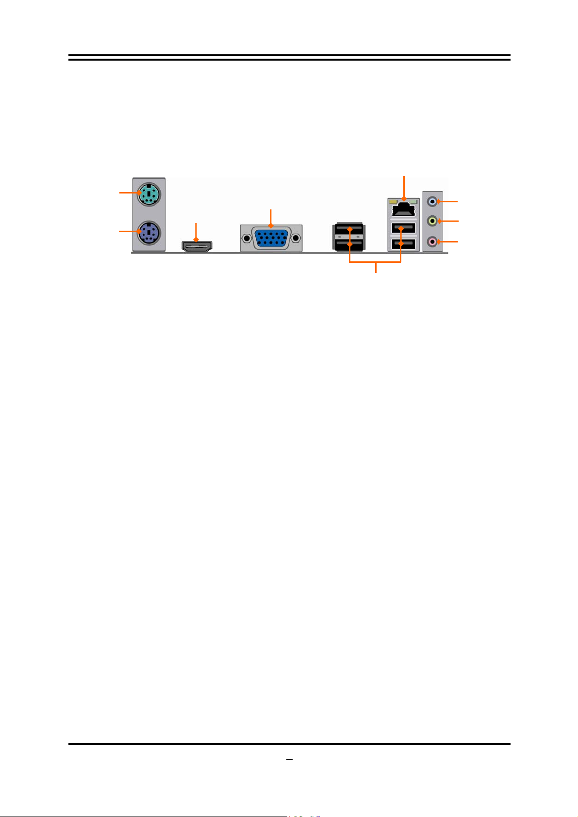
3-1 I/O Back Panel Connectors
(1) PS/2 Mouse & PS/2 Keyboard Connector: KB
The connectors are for PS/2 keyboard and PS/2 Mouse. The green one is PS/2
mouse port and the purple one is PS/2 keyboard port.
(2) High-Definition Multimedia Interface: HDMI
This point-to-point interface is for audio and video signals designed as a
single-cable solution for home theater and consumer electronics equipment.
(3) D-Sub 15-pin Connector: VGA1
VGA is the 15-pin D-Subminiature female connector; it is for the display devices,
such as the CRT monitor, LCD monitor and so on.
(4) USB 2.0 Ports: USB2/ UL1 (Middle & Bottom)
The connectors are 4-pin USB 2.0 connectors to connect USB devices to the
system board.
(5) RJ-45 LAN Port connector: UL1(Top)
The connector is standard RJ-45 connector for Network.
(6) Audio Line-In, Line-Out, MIC Connector: AUDIO1
These Connectors are 3 Phone-Jack for LINE-OUT, LINE-IN, and MIC audio
connections.
Line-in: (BLUE) Audio input to sound chip
Line-out: (GREEN) Audio output to speaker
MIC: (PINK) Microphone Connector
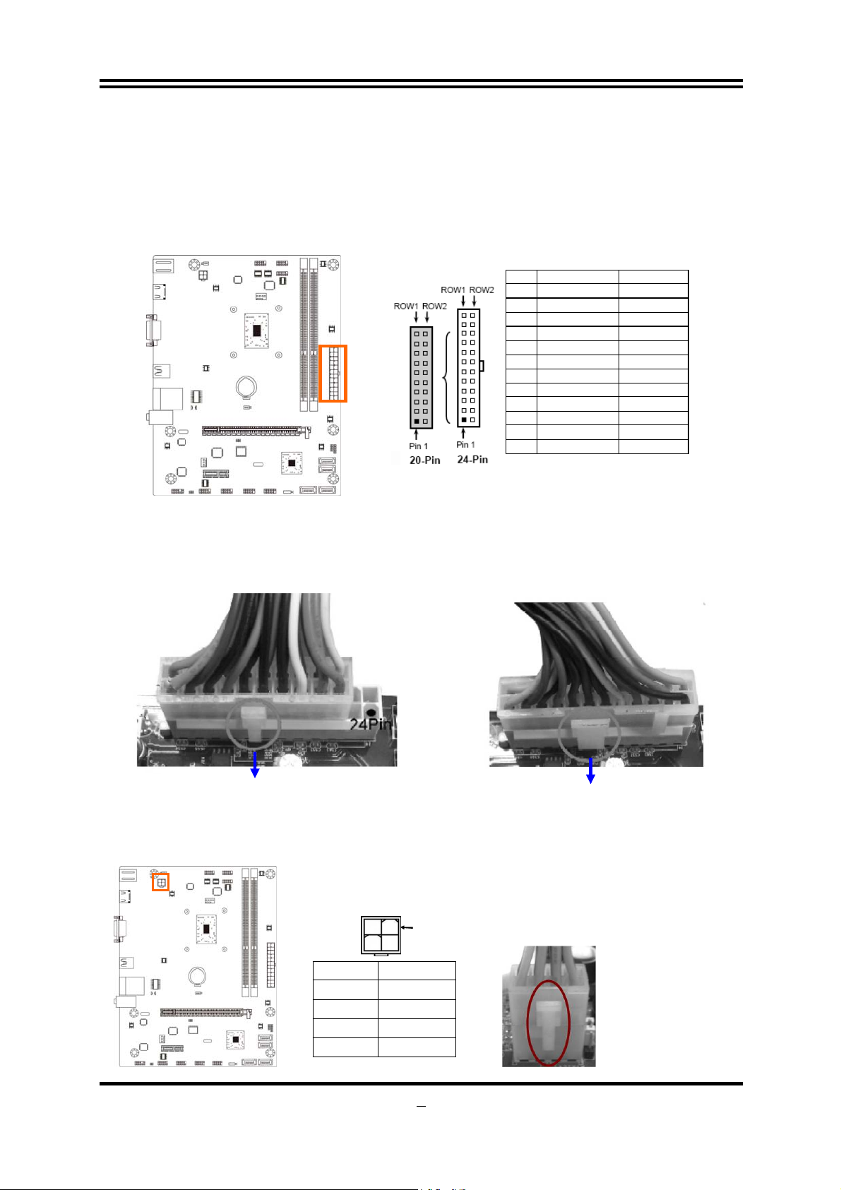
3-2 Motherboard Internal Connectors
(1) Main Power Connector (24-pin block): ATXPWR
ATX Power Supply connector: This is a new defined 24-pins connector that
usually comes with ATX case. The ATX Power Supply allows using soft power
on momentary switch that connect from the front panel switch to 2-pins Power
On jumper pole on the motherboard. When the power switch on the back of the
ATX power supply turned on, the full power will not come into the system board
until the front panel switch is momentarily pressed. Press this switch again will
turn off the power to the system board.
USB 2.0 Ports
PS/2 Keyboard
Port
PS/2 Mouse
Port Line-In
Line-Out
MIC-In
VGA Port
RJ-45 LAN Port
HDMI Port

7
** We recommend that you use an ATX 12V Specification 2.0-compliant power
supply unit (PSU) with a minimum of 350W power rating. This type has 24-pin
and 4-pin power plugs.
** If you intend to use a PSU with 20-pin and 4-pin power plugs, make sure that the
20-pin power plug can provide at least 15A on +12V and the power supply unit
has a minimum power rating of 350W. The system may become unstable or may
not boot up if the power is inadequate.
PIN ROW1 ROW2
1 +3.3V +3.3V
2 +3.3V -12V
3 GND GND
4 +5V PS_ON
5 GND GND
6 +5V GND
7 GND GND
8 Power OK -5V
9 +5V Stand by +5V
10 +12V +5V
11 +12V +5V
12 +3.3V GND
24-
p
in Main Power Connector
** If you are using a 20-pin power plug, please refer to Figure1 for power supply
connection. Power plug form power supply and power connectors from motherboard
both adopt key design to avoid mistake installation. You can insert the power plug into
the connector with ease only in the right direction. If the direction is wrong it is hard to
fit in and if you make the connection by force if is possible.
Figure1:20-pinpowerplug Figure2:24-pin power plug
(2) ATX 12V Power Connector (4-pin block): ATX12V
This is a new defined 4-pin connector that usually provides power to CPU. The
system will not start if this connector is not connected correctly.
Pin1
Pin No. Definition
1 GND
2 GND
3 +12V
4 +12V

8
(3) SATAII Port connectors: SATA2,SATA3,SATA4
SATA2/3/4 port supports SATA 6Gb/s specification. Please connect SATAIII
device to the port with SATAIII cable. One port supports one SATA device.
Pin No. Defnition
1 GND
2 TXP
3 TXN
4 GND
5 RXN
6 RXP
7 GND
(4) SATAIII Port connectors: SATA1
SATA1 port supports SATA 6Gb/s specification. Please connect SATAIII device
to the port with SATAIII cable. One port supports one SATA device.
Pin No. Defnition
1 GND
2 TXP
3 TXN
4 GND
5 RXN
6 RXP
7 GND
(5) FAN Headers: SYSFAN1 (3-pin), CPUFAN1 (4-pin)
These connectors support cooling fans of 350mA (4.2 Watts) or less, depending
on the fan manufacturer, the wire and plug may be different.
FAN Headers
CP
U
FAN1
Pin1 GND
Fan Clock
SYSFAN1
Control
Fan Clock
+12V Fan Power
Pin1
GND
+
12V Fan Powe
r

9
3-3 Headers
(1) Line-Out/MIC Header for Front Panel (9-pin): FP_AUDIO
These headers connect to Front Panel Line-out, MIC connector with cable.
Pin 1
Lineout2-L
Lineout2-R
Sense-FB
Audio-GND
LINE2-JD
Audio-JD
2
9
10
KEY
MIC2-L
MIC2-JD MIC2-R
(2) SPDIF Out header (2-pin): HDMI_SPDIF1
The SPDIF output is capable of providing digital audio to external speakers or
compressed AC3 data to an external Dolby digital decoder. Use this feature only
when your stereo system has digital input function.
Pin1
GND
HDMI_SPDIF_OUT
(3) Speaker Header: SPEAK1
This 4-pin header connects to the case-mounted speaker. See the figure below.
(4) Power LED Header: PWR LED1/PWRLED
The Power LED is light on while the system power is on. Connect the Power
LED from the system case to this pin.
(5) Hard Disk Activity LED: HD LED
This header connects to the hard disk activity indicator light on the case.
(6) Reset Switch: RESET
This 2-pin header connects to the case-mounted reset switch for rebooting your
computer without having to turn off your power switch. This is a preferred
method of rebooting in order to prolong the life of the system’s power supply.
See the figure below.
(7) Power Switch: PWR BTN
This 2-pin header connects to the case-mounted power switch to power
ON/OFF the system.

10
HDLED
RESET
HDDLED+
GND
PWRLED+
PWRBTN GND
PWRLED- HDDLED-
RSTSW
NC
PWRB TN
JW_FP
Pin 1
2
PWR LED
PWRLED Pin 1
SPEAK
SPK+
NC
NC
SPK-
PWRLED+
PWRLED+
PWRLED-
Pin 1
(8) USB 2.0 Port Headers (9-pin): F_USB1/ F_USB2
These headers are used for connecting the additional USB 2.0 port plugs. By
attaching an option USB cable, your can be provided with two additional USB 2.0
plugs affixed to the back panel.
Pin 1
VCC
-DATA
GND
+DATA
VCC
NC
-DATA
GND
+DATA
(9) Serial Port header (9-pin): COM1/2/3/4
COM1/2/3/4 header supports serial port expansion for user to connect external
MODEM or other devices that supports Serial Communications Interface.
DCD
Pin1
Pin2
TXD
GND
RTS
RI
RXD
DTR
DSR
CTS

11
Chapter 4
Useful Help
4-1 How to Update BIOS
Solution 1: Updating BIOS under DOS:
1. Prepare a bootable disk. (You may make one by click START click RUN type SYS
A: click OK)
2. Download upgrade tools and the latest BIOS files of the motherboard from official
website and then make a copy of it to your bootable floppy disk after
decompressing these files
3. Insert the disk into A: start your computer and then type in
“A:\xxxxxx.BAT”(xxxxxxx being the file name of the latest BIOS )
4. Type Enter to update and flash the BIOS. The system will restart automatically
when BIOS is upgraded.
Solution 2: Updating BIOS under Windows operating system:
1. Download Windows version BIOS from our website.
2. Unzip the downloaded file.
3. Double click EXE file to activate it and follow on-screen instructions for further
operations.
4-2 Trouble Shooting
Problem Solution
No power to the system to the all
power light don’t illuminate, fan inside
power supply doesn’t turn on.
1. Make sure power cable is security
plugged in. 2. Replace cable. 3.
Contact technical support.
System inoperative. Keyboard lights
are on, power indicator lights are lit,
and hard drive is spinning.
Using ever pressure on both ends of
the DIMM , press down firmly until the
module snaps into places.
System doesn’t boot from hard disk
drive, can be booted from optical drive. 1. Check cable running from disk to
disk controller board. .Make sure both
ends are securely plugged in, check
the drive type in the standard CMOS
setup. 2. Backing up the hard drive is
extremely important .All hard disks are
capable of breaking down at any time.
System only boots from optical
drive .Hard disk can be read and
applications can be used but booting
from hard disk is impossible.
1. Back up date and applications files.
2. Reformat the hard drive. Reinstall
applications and date using backup
disks.
Screen message says “Invalid
Configuration” or “CMOS Failure” Review system‘s equipment .Make
sure correct information on is in setup.

12
Appendix
Special Features of the Motherboard
1. Thunder Protection Feature
This motherboard series are integrated with double thunder-protection walls, one from
network port and the other from LAN chip. Laboratory test statistics on IEC61000-4-5
(1.2-50us) specialized thunderbolt surge tests have verified that motherboard can
endure up to 9KV thunderbolt surge and protect the system from possible thunder
damage.
2. CPU Vcore Solid Capacitors-High-polymer Solid Electrolysis
Aluminum Capacitors
The motherboard adopts CPU Vcore solid capacitors to make it possible for
motherboard to work from 55 degrees Centigrade below zero to 125 degrees
centigrade. CPU Vcore capacitors possess superior physical characteristics to
prolong product life ten times than corresponding motherboard without capacitors
every time working temperature increases 20 degrees. Life of product of motherboard
with solid capacitors declines only 10% of those without solid capacitors as well under
same conditions.
3. CPU Smart Fan —The Noise Management System
It’s never been a good idea to gain the performance of your system by sacrificing its
acoustics. CPU Smart Fan Noise Management System is the answer to control the
noise level needed for now-a-day’s high performance computing system. The system
will automatically increase the fan speed when CPU operating loading is high, after
the CPU is in normal operating condition, the system will low down the fan speed for
the silent operating environment. The system can provide the much longer life cycle
for both CPU and the system fans for game use and business requirements.

Table of contents
Other JETWAY Motherboard manuals

JETWAY
JETWAY JNP793D2-3160 User manual

JETWAY
JETWAY 740DMR1A User manual

JETWAY
JETWAY S450R2A User manual

JETWAY
JETWAY 845GEA1A User manual

JETWAY
JETWAY V333UR1A User manual

JETWAY
JETWAY V6FP User manual

JETWAY
JETWAY 531CF-6 User manual

JETWAY
JETWAY MU03 Series User manual

JETWAY
JETWAY P4845DDA User manual

JETWAY
JETWAY 865GVBMS User manual

JETWAY
JETWAY IN73M3 User manual

JETWAY
JETWAY NF697 Series User manual

JETWAY
JETWAY V266AR1A User manual

JETWAY
JETWAY 867ASR2A User manual

JETWAY
JETWAY 830CF User manual

JETWAY
JETWAY NC8J Series User manual

JETWAY
JETWAY P4X400DBR3A User manual

JETWAY
JETWAY 694TAS3A User manual

JETWAY
JETWAY K8T8AS - REV 3.0 User manual

JETWAY
JETWAY MI05 Series User manual