JETWAY NU95 Series User manual

NU95 Series
User’s Manual
NO. G03-NU95-F
Revision: 1.0
Release date: December 4, 2020
Trademark:
* Specifications and Information contained in this documentation are furnished for information use only, and are
subject to change at any time without notice, and should not be construed as a commitment by manufacturer.

ii
Environmental Protection Announcement
Do not dispose this electronic device into the trash while discarding. To minimize
pollution and ensure environment protection of mother earth, please recycle.

iii
ENVIRONMENTAL SAFETY INSTRUCTION................................................................................... iv
USER’S NOTICE.................................................................................................................................... v
MANUAL REVISION INFORMATION................................................................................................ v
ITEM CHECKLIST..................................................................................................................................v
CHAPTER 1 INTRODUCTION OF THE MOTHERBOARD
1-1 FEATURE OF MOTHERBOARD.........................................................................................1
1-2 SPECIFICATION.................................................................................................................... 2
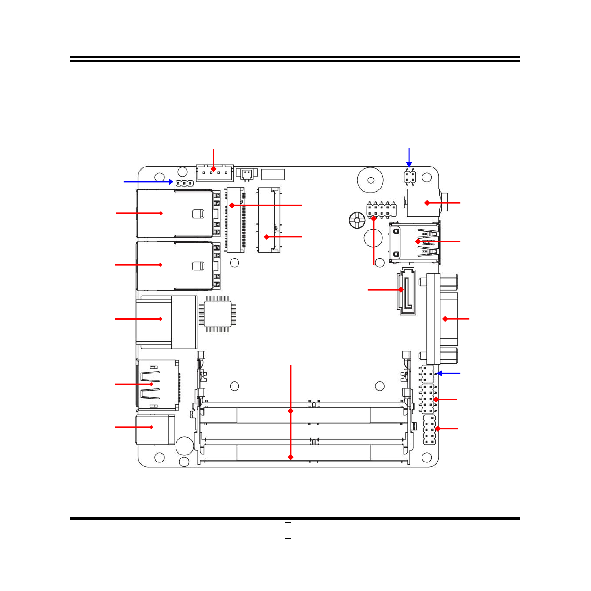
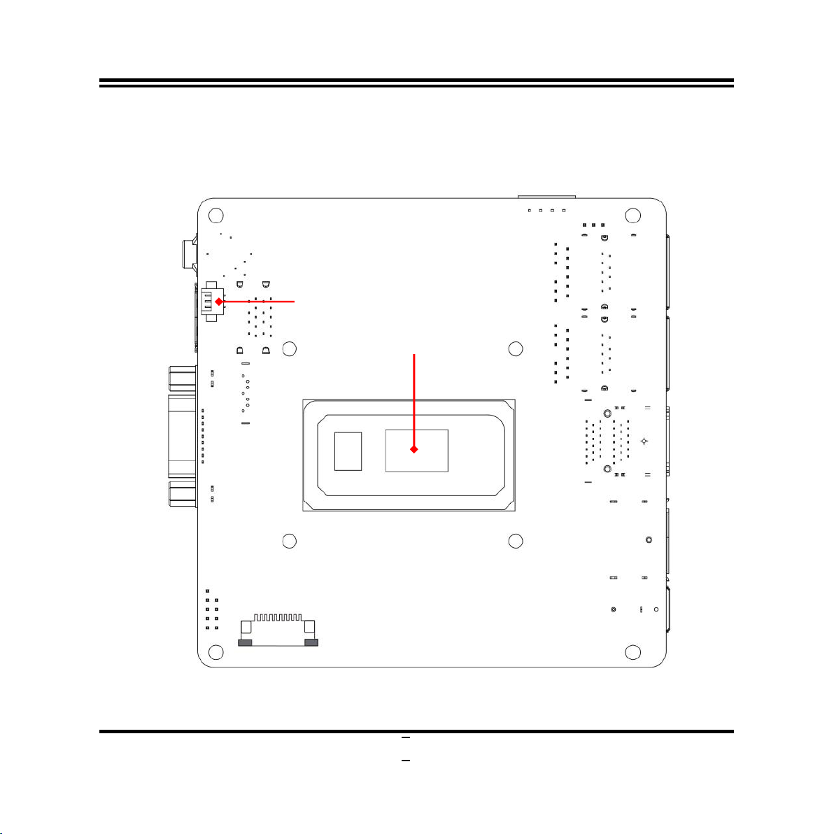
1-3 LAYOUT DIAGRAM...............................................................................................................3
CHAPTER 2 HARDWARE INSTALLATION
2-1 JUMPER SETTING................................................................................................................ 7
2-2 CONNECTORS, WAFERS AND HEADERS..................................................................... 9
2-2-1 CONNECTORS........................................................................................................9
2-2-2 WAFERS & HEADERS.......................................................................................... 13
CHAPTER 3 INTRODUCING BIOS
3-1 ENTERING SETUP................................................................................................................ 15
3-2 BIOS MENU SCREEN........................................................................................................... 16
3-3 FUNCTION KEYS...................................................................................................................17
3-4 GETTING HELP......................................................................................................................17
3-5 MEMU BARS...........................................................................................................................18
3-6 MAIN MENU............................................................................................................................ 19
3-7 ADVANCED MENU................................................................................................................20
3-8 CHIPSET MENU..................................................................................................................... 33
3-9 SECURITY MENU.................................................................................................................. 36
3-10 BOOT MENU........................................................................................................................... 39
3-11 SAVE & EXIT MENU..............................................................................................................40
TABLE OF CONTENT

iv
Environmental Safety Instruction
Avoid the dusty, humidity and temperature extremes. Do not place the product in
any area where it may become wet.
0 to 60 centigrade is the suitable temperature. (The figure comes from the request
of the main chipset)
Generally speaking, dramatic changes in temperature may lead to contact
malfunction and crackles due to constant thermal expansion and contraction from
the welding spots’ that connect components and PCB. Computer should go
through an adaptive phase before it boots when it is moved from a cold
environment to a warmer one to avoid condensation phenomenon. These water
drops attached on PCB or the surface of the components can bring about
phenomena as minor as computer instability resulted from corrosion and oxidation
from components and PCB or as major as short circuit that can burn the
components. Suggest starting the computer until the temperature goes up.
The increasing temperature of the capacitor may decrease the life of computer.
Using the close case may decrease the life of other device because the higher
temperature in the inner of the case.
Attention to the heat sink when you over-clocking. The higher temperature may
decrease the life of the device and burned the capacitor.

v
USER’S NOTICE
COPYRIGHT OF THIS MANUAL BELONGS TO THE MANUFACTURER. NO PART OF THIS MANUAL,
INCLUDING THE PRODUCTS AND SOFTWARE DESCRIBED IN IT MAY BE REPRODUCED, TRANSMITTED
OR TRANSLATED INTO ANY LANGUAGE IN ANY FORM OR BY ANY MEANS WITHOUT WRITTEN
PERMISSION OF THE MANUFACTURER.
THIS MANUAL CONTAINS ALL INFORMATION REQUIRED TO USE THIS MOTHER-BOARD SERIES AND WE
DO ASSURE THIS MANUAL MEETS USER’S REQUIREMENT BUT WILL CHANGE, CORRECT ANY TIME
WITHOUT NOTICE. MANUFACTURER PROVIDES THIS MANUAL “AS IS” WITHOUT WARRANTY OF ANY
KIND, AND WILL NOT BE LIABLE FOR ANY INDIRECT, SPECIAL, INCIDENTIAL OR CONSEQUENTIAL
DAMAGES (INCLUDING DAMANGES FOR LOSS OF PROFIT, LOSS OF BUSINESS, LOSS OF USE OF DATA,
INTERRUPTION OF BUSINESS AND THE LIKE).
PRODUCTS AND CORPORATE NAMES APPEARING IN THIS MANUAL MAY OR MAY NOT BE
REGISTERED TRADEMARKS OR COPYRIGHTS OF THEIR RESPECTIVE COMPANIES, AND THEY ARE
USED ONLY FOR IDENTIFICATION OR EXPLANATION AND TO THE OWNER’S BENEFIT, WITHOUT
INTENT TO INFRINGE.
Manual Revision Information
Reversion Revision History Date
1.0 First Edition December 4, 2020
Item Checklist
Motherboard
Cable(s)

1
Chapter 1
Introduction of the Motherboard
1-1 Feature of Motherboard
Onboard Intel®10th Comet Lake i5-10210U Series MCP Processor, with low
power consumption never denies high performance
Support 2* DDR4 2666 MHz SO-DIMM, up to 64GB
Integrated with 2 *Intel Gigabit Ethernet LAN chip
1* M.2 E-key 2230 slot, PCIex1/USB2.0 interface with support for CNVi
1* M.2 M-key 2242 slot, SATA interface
1* SATAIII device
2* HDMI ports & 1* Display port, supports Triple Independent Display
1* Line-out/MIC combo
Support up to 4 * USB 3.2 Gen.2 port (External) & 2 * USB 2.0 port (Internal)
1 * COM port supports RS232/422/485
Support CPU Smart FAN
Compliance with ErP standard
Support Watchdog function
Solution for Digital Signage, Cloud Applications, IoT & Industrial Automation

2
1-2 Specification
Spec
Description
Design
NUC form factor; PCB size: 10.1 cm x 10.1 cm
Embedded CPU
Intel®10th Comet Lake series MCP CPU,I5-10210U QC, 1.6GHz,
15W
*Note:CPU model may vary from different IPC options. Please consult
your dealer for more information of onboard CPU.
Memory Slot
2*DDR4 SO-DIMM slot
Support 2* DDR4 2666MHz SO-DIMM up to 64GB
Expansion Slot
1* M.2 E-key,type-2230 slot supports CNVi (M2E)
*Note:M2E slot maximum current limit is 1A while using 3.3V.
Storage
1* SATAIII 6Gb/s port
1* M.2 M-key,type-2242 SATAIII interface slot (M2M)
*Note:M2Mslot maximum current limit is 1A while using 3.3V.
LAN Chip
Integrated with 1* Intel i211AT Gigabit Ethernet LAN chip & 1*
Intel i219-LM Gigabit PHY LAN chip
Support Fast Ethernet LAN function of providing
10/100/1000Mbps Ethernet data transfer rate
Audio Chip
Realtek ALC662-GR HD audio chip
BIOS
AMI 128MB Flash ROM
Rear Panel I/O
1* 12V~24V DC-in system power Jack
1* Display Port (PS:This function is converted from EDP to DP,
only display no audio output)
1* HDMI 2.0 port (Max Resolution: 4096×2304@60Hz)
1* HDMI 1.4 port (Max Resolution: 4096×2304@30Hz)
2* RJ-45 GbE LAN port
2* USB 3.2 (Gen.2) port
Front Panel I/O
1* Serial port (COM supports RS232/422/485 function)
2* USB 3.2 (Gen.2) port
1* Audio Line-Out & MIC combo jack

3
Internal I/O
1* SATA Power connector
1* CPU FAN wafer (on the backside)
1* JW_FP front panel header
1* GPIO header
1* 9-Pin USB 2.0/1.1 header for 2* USB 2.0/1.1 ports
*Note: Many PCs now include XHCI USB controllers which allow for the support of USB 3.0 and
higher USB speeds. This inclusion of XHCI controllers has lessened the need for EHCI USB
controllers within platforms. However, legacy operating systems (OS) may not natively recognize
XHCI controllers. You might need to pre-install XHCI driver while desiring to install a non-XHCI OS
(ex.Windows* 7) on Intel platforms which do not include EHCI controllers. Please contact your
representative for more details.
1-3 Layout Diagram
Rear IO Panel Diagram:
Front IO Panel Diagram:
Line-OUT/MIC
Combo Port
RS232/422/485
Serial Port
USB 3.2(Gen.2) Ports
RJ-45 LAN Ports
Display Port
HDMI 2.0 Port
HDMI 1.4 Port
12V~24V DC-in
Power Jack
USB 3.2(Gen.2) Ports

4
Internal Diagram-Front Side:
M.2 M-Key Slot
(M2M)
SATA HDD
Power-Out
Connector
RJ-45 LAN Port
Over
USB 3.2(Gen.2) Port
RJ-45 LAN Port
Over
USB 3.2(Gen.2) Port
HDMI Ports
Display Ports
12V~24V DC-in
Power Jack
M.2 E-Key Slot
(M2E)
USB 2.0 Port Header
SATAIII Port
Serial Port
DDR4
SODIMM Slots
GPIO Header
Front Panel
Header
JPCOM
JP1
JBAT
Line_Out / MIC
Combo Port
USB 3.2(Gen.2)
Ports

5
Internal Diagram-Back Side:
Intel CPU
CPUFAN Wafer

6
Connectors
P/N
Name
UL1/UL2
Top: RJ-45 LAN Port Connector
Bottom: USB 3.2 (Gen.2) Port Connector
HDMI1
Top: HDMI 2.0 Connector
Bottom: HDMI 1.4 Connector
DP
Display Port Connector
DC_IN
12V~24V DC–in System Power Jack
COM
RS232/422/485 Serial Port Connector
USB30
USB 3.2 (Gen.2) Port Connector
AUDIO
Line-Out/MIC Combo Connector
SATA
SATAIII Port Connector
SATAPW
SATA Power out Connector
Headers & Wafers
P/N
Name
Description
Pitch
JW_FP
Front Panel Header
9-pin Block
2.0mm
GPIO_CON
GPIO Header
10-pin Block
2.0mm
FP_USB1
USB 2.0 Port Header
9-pin Block
2.0mm
CPUFAN
(backside)
CPUFAN Wafer
3-pin Block
1.25mm
Jumper
P/N
Name
Description
Pitch
JPCOM
COM Port Pin9 Function Select
4-Pin Block
2.0mm
JBAT
Pin (1-2): Clear CMOS RAM Setting
Pin (3-4): Flash Descriptor Security Override
4-Pin Block
2.0mm
JP1
ATX Mode & AT Mode Select
3-Pin Block
2.0mm

7
Chapter 2
Hardware Installation
2-1 Jumper Setting
JPCOM (4-pin): COM Port Pin9 Function Select
*Note:Maximum current limit is 500mA while using 5V or 12V.
Pin (1-2) of JBAT (6-pin): Clear CMOS RAM Setting
1-2 Closed: Clear CMOS (One Touch).
1-2 Open: Normal(Default);
PIN(1-2) of JBAT: Clear CMOS
Pin1
3
Pin1
2
4
Pin1
2
3
4
JPCOM
JBAT

8
Pin (3-4) of JBAT (6-pin): Flash Descriptor Security Override
PIN(3-4) of JBAT: Flash Override
Pin1
3
Pin1
2
4
Pin1
2
3
4
3-4 Open: Enable Security Measures
in the Flash Descriptor(Default);
;
3-4 Closed: Disable Security Measures
in the Flash Descriptor(Override).
JP1 (3-pin): ATX Mode/ AT Mode Select
2-3 Closed: AT Mode Selected.
JP1
→
ATX/AT M ode Select
1-2 Closed: ATX Mode Selected;
1
3
1
3
ATX Mode Selected: Press power button to power on after power input ready;
AT Mode Selected: Directly power on as power input ready.
JBAT
JP1

9
2-2 Connectors, Wafers and Headers
2-2-1 Connectors
Rear IO Panel Diagram:
Front IO Panel Diagram:
Line-OUT/MIC
Combo Port
RS232/422/485
Serial Port
USB 3.2(Gen.2) Ports
RJ-45 LAN Ports
Display Port
HDMI 2.0 Port
HDMI 1.4 Port
12V~24V DC-in
Power Jack
USB 3.2(Gen.2) Ports

10
Icon
Name
Function
Power Connector
12V DC–in system power connector
For user to connect compatible power adapter to
provide power supply for the system.
Display Port
To the system to corresponding display device with
compatible display port cable.
HDMI Port
To connect display device that support HDMI
specification.
Top: 1* HDMI 2.0 port (Max Resolution :
4096×2304@60Hz)
Bottom:1* HDMI 1.4 port (Max Resolution :
4096×2304@30Hz)
RJ-45 LAN Port
This connector is standard RJ-45 LAN jack for
Network connection.
USB 3.1 (Gen.2)
Port
To connect USB keyboard, mouse or other devices
compatible with USB 3.2 (Gen.2) specification. Ports
support up to 10Gbps data transfer rate.
Line-Out/MIC
Combo Connector
This connector can functions as audio Line-Out jack
and MIC jack with compatible cables & devices.
RS232/422/485
Serial Port
Mainly for user to connect external MODEM or other
devices that supports
Serial Communications Interface.
*Note: 1.Maximum current limit for USB ports:
※
UL1+UL2 total is 1.5A.
※
USB30+FP_USB1 (header) total is 1.5A.
2. DP port is converted from EDP, only display function, not support audio output.

11
(1) COM (9-pin Block): RS232/422/485 Serial Port
COM port can function as RS232/422/485 port. In normal settings COM functions as
RS232 port. With compatible COM cable they can function as RS422 or RS 485 port.
User also needs to go to BIOS to set ‘Transmission Mode Select’for COM (refer to
Page 25) at first, before using specialized cable to connect different pins of this port.
1
2
3
4
5
6
7
8
9
RS232 DCD#
RS232 SIN
RS232 SOUT
RS232 DTR#
GND
RS232 RI#
RS232 CTS#
RS232 RTS#
RS232 DSR#
Pin1
For RS422 Mode
RS422TX-(B)
RS422TX+(A)
RS422RX+(A)
RS422RX-(B)
(B)
For RS485 Mode
RS485 D-(B)
RS485 D+(A)

12
(2) SATA (7-pin Block): SATAIII Port connector
The board comes with a SATAIII port that supports 6GB/s transfer rate.
Pin No.
Definition
1
GND
2
TXP
3
TXN
4
GND
5
RXN
6
RXP
7
GND
(3) SATAPW (4-pin): SATA HDD Power-Out Connector
*Note:Maximum current limit is 2A while using 5V or 12V working voltage.
SATAPW
SATA

13
2-2-2 Wafers & Headers
(1) JW_FP1 (9-pin): Front Panel Header
GND
RSTSW
Pi n
1
2
HDDLED+
HDDLED-
VCC5V
PWRLED+
PWRLED-
PWRBTN
GND
*Note: Maximum current limit is 1A while using 5V working voltage.
(2) GPIO_CON (10-pin): GPIO Header
GND
VCC5V
Pin1
2
SIO_GP20
SIO_GP22
SIO_GP24
SIO_GP26
SIO_GP21
SIO_GP23
SIO_GP25
SIO_GP27
*Note: Maximum current limit is 1A while using 5V working voltage.
JW_FP1
GPIO_CON

14
(3) FP_USB1(9-pin): USB 2.0 Port Header
Pin1
VCC5V
-DATA
GND
+DATA
VCC5V
NC
C
-DATA
GND
+DATA
*Note: Maximum current limit is 1.5A
in total while using 5V working voltage.
2
(4) CPUFAN (3-pin): CPUFAN Wafer
Pin No.
Definition
1
FAN_OUT
2
GND
3
Fan Detect
*Note: This is a 5V DC FAN and deliver up to 0.6A output current.
FP_USB1
CPUFAN
(Backside)

15
Chapter 3
Introducing BIOS
Notice! The BIOS options in this manual are for reference only. Different
configurations may lead to difference in BIOS screen and BIOS
screens in manuals are usually the first BIOS version when the board is
released and may be different from your purchased motherboard.
Users are welcome to download the latest BIOS version form our
official website.
The BIOS is a program located on a Flash Memory on the motherboard. This program
is a bridge between motherboard and operating system. When you start the computer,
the BIOS program will gain control. The BIOS first operates an auto-diagnostic test
called POST (power on self test) for all the necessary hardware, it detects the entire
hardware device and configures the parameters of the hardware synchronization.
Only when these tasks are completed done it gives up control of the computer to
operating system (OS). Since the BIOS is the only channel for hardware and software
to communicate, it is the key factor for system stability, and in ensuring that your
system performance as its best.
3-1 Entering Setup
Power on the computer and by pressing <Del> immediately allows you to enter Setup.
If the message disappears before your respond and you still wish to enter Setup,
restart the system to try again by turning it OFF then ON or pressing the “RESET”
button on the system case. You may also restart by simultaneously pressing <Ctrl>,
<Alt> and <Delete> keys. If you do not press the keys at the correct time and the
system does not boot, an error message will be displayed and you will again be asked
to
Press <Del> to enter Setup; press < F7> to enter pop-up Boot menu.
Table of contents
Other JETWAY Motherboard manuals

JETWAY
JETWAY S447R3A User manual

JETWAY
JETWAY NF9HB Series User manual

JETWAY
JETWAY I406R1A User manual

JETWAY
JETWAY P400MTR2A User manual

JETWAY
JETWAY V266AR1A User manual

JETWAY
JETWAY J-630AF User manual

JETWAY
JETWAY G03-NC9T-F User manual

JETWAY
JETWAY NF795-Q170 User manual

JETWAY
JETWAY P4X40DAR2A User manual

JETWAY
JETWAY 917PDCP User manual

JETWAY
JETWAY POLARIS400 User manual

JETWAY
JETWAY 693AS User manual

JETWAY
JETWAY NF591 User manual

JETWAY
JETWAY P4MBMS - REV 1.0 User manual

JETWAY
JETWAY I401R2C User manual

JETWAY
JETWAY B 860T User manual

JETWAY
JETWAY BX2000 User manual

JETWAY
JETWAY 740DMR1A User manual

JETWAY
JETWAY NF9U-F User manual

JETWAY
JETWAY K8M8MSR1A User manual