JEWELL 700 Series User manual

Model 700 Series User's Manual
B-88-1016, Rev. G
TABLE OF CONTENTS
1.0 General Information......................................................................................................................1
1.1 Introduction............................................................................................................................1
1.2 Technical Features.................................................................................................................6
1.3 Specifications..........................................................................................................................6
2.0 Installation......................................................................................................................................7
2.1 Initial Check-Out Procedures.................................................................................................7
2.2 Installing Platform Tiltmeters..............................................................................................11
2.3 Installing Surface Mount Tiltmeters.....................................................................................11
3.0 Recording Tiltmeter Data with External Recorders.................................................................12
4.0 Grounding and Transient Protection.........................................................................................12
5.0 Converting Readings to Tilt Angles and Temperatures...........................................................12
6.0 Maintenance and Troubleshooting.............................................................................................13
6.1 Introduction..........................................................................................................................13
6.2 Routine Maintenance............................................................................................................14
6.3 Determining the Cause of Malfunctions...............................................................................14
Appendix A: Warranty and Assistance..............................................................................................17
Appendix B: Custom Specifications for Your 700-Series Tiltmeter................................................18
Appendix C: Guidelines for Installing Surface Mount Tiltmeters..................................................20
Appendix D: Angle Conversion Chart...............................................................................................21
Appendix E: Revision Record.............................................................................................................22
TABLE OF FIGURES
Figure 1: Platform Tiltmeter, Model 701-2........................................................................................... 2
Figure 2: Floor Mount Tiltmeter, Model 711-2..................................................................................... 3
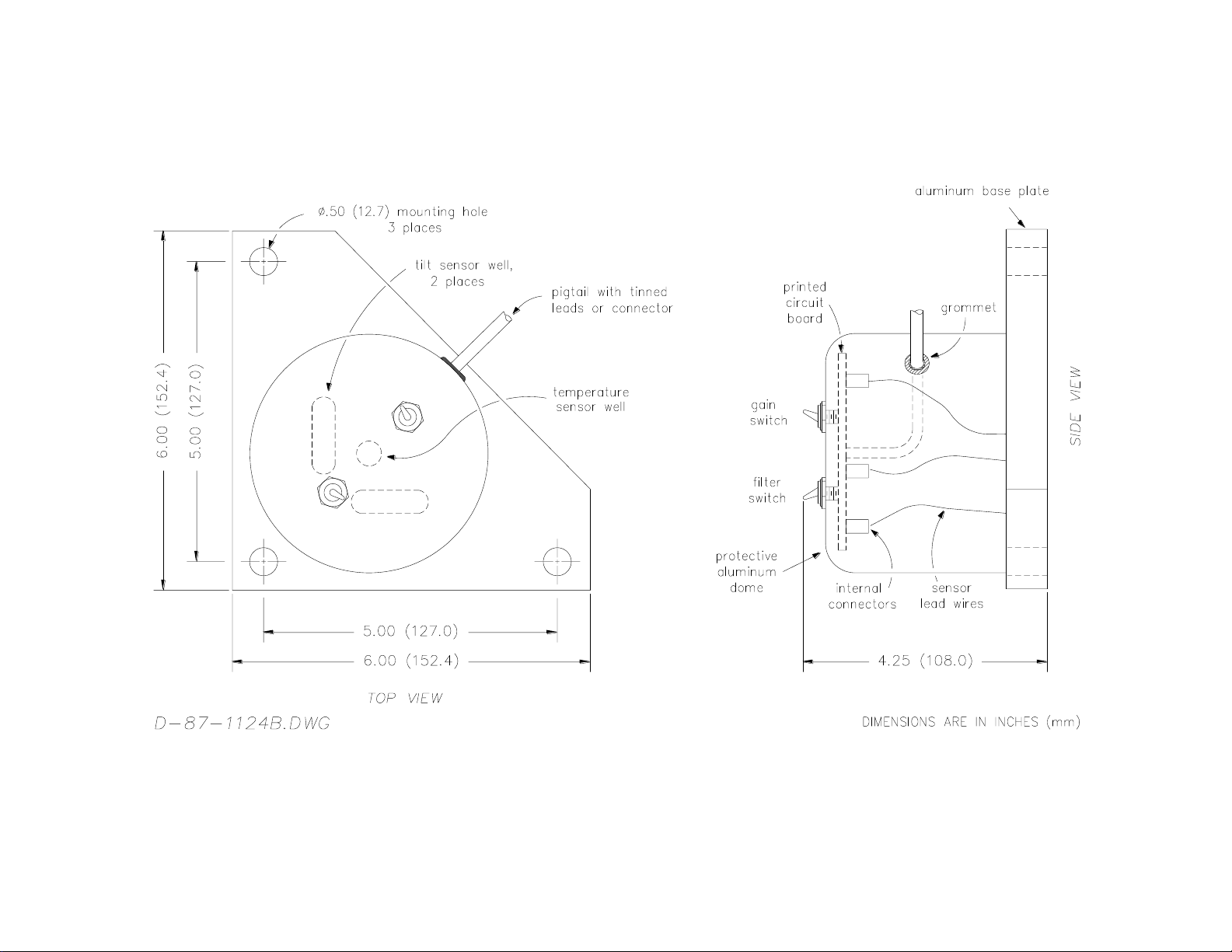
Figure 3: Platform Tiltmeter, Model 702 .............................................................................................. 4
Figure 4: Floor Mount Tiltmeter, Model 712........................................................................................ 5
Figure 5a: Platform and Floor Mount Tiltmeter Sign Convention.......................................................... 9
Figure 5b: Wall Mount Tiltmeter in Installed Position ......................................................................... 10
Figure 6: Earth Ground Circuit............................................................................................................ 13
Figure 7: Model 83162 Dual-Channel Signal Conditioning Card....................................................... 16
Figure 8: Installing 700-Series Tiltmeters........................................................................................... 20

Model 700 Series User's Manual 1
B-88-1016, Rev. G
1.0 General Information
1.1 Introduction
700-Series Platform and Surface Mount Tiltmeters are dual-axis, analog output tiltmeters, designed
for high-sensitivity, low power consumption, durability, and reliability under rugged field conditions.
Suitable for geotechnical and geophysical projects in remote locations, they will also provide years of
trouble-free service in industrial and laboratory applications. They are used worldwide for monitoring earth
and structural deformation at dam sites, mines, volcanoes, power plants, engineering and scientific
laboratories, bridges, highways, and many other industrial and scientific facilities.
Platform and surface mount tiltmeters are essentially the same and consist of an aluminum or
stainless steel base plate, aluminum or stainless steel cover (dome), sensors, PC board, connectors, and
switches. They differ in that platform tiltmeters (Figure 1) have adjustable legs that are used for leveling
the tiltmeters on any hard horizontal surface. In contrast, surface mount tiltmeters (Figure 2) have holes in
the base plate and are mounted over threaded studs embedded in the measurement surface. Nuts are used to
adjust the position of surface mount tiltmeters and to stably lock the tiltmeter in place for long-term
measurements.
Jewell Instruments platform tiltmeters are designated by model numbers 701 and 702, which
represent the aluminum (Figure 1) and stainless steel versions, respectively. Surface mount tiltmeters are
available in floor mount (Models 711 and 712), wall mount (Models 716 and 717) and ceiling mount
(Models 714 and 715) versions. In the preceding pairs of model numbers, the first number is an aluminum
tiltmeter and the second is a stainless steel tiltmeter. Models 711, 702 and 712 are shown in Figure 2, 3 and
4. By using a Model 719 Universal Mounting Bracket, the same surface mount tiltmeter can be installed on
the floor, wall or ceiling. This mounting bracket will also attach a standard platform tiltmeter to any vertical
surface.

Model 700 Series User's Manual
B-88-1016, Rev. G 2
Figure 1: Platform Tiltmeter, Model 701-2.

Model 700 Series User's Manual
B-88-1016, Rev. G 3
Figure 2: Floor Mount Tiltmeter, Model 711-2.

Model 700 Series User's Manual
B-88-1016, Rev. G 4
Figure 3: Platform Tiltmeter, Model 702.

Model 700 Series User's Manual
B-88-1016, Rev. G 5
Figure 4: Floor Mount Tiltmeter, Model 712.

Model 700 Series User's Manual 6
B-88-1016, Rev. G
1.2 Technical Features
Platform and surface mount tiltmeter models share these technical features:
•They sense a change in tilt angle with an electrolytic sensor, similar to a spirit level.
•All electronics reside on a single internal printed-circuit board.
•All circuit board external connections are gold-plated for long life and noise-free operation.
•All resistors are premium quality, 1% tolerance, metal-film type.
•All tiltmeters are hand-assembled, calibrated, and tested at our plant under stringent quality control
standards.
•JEWELL maintains complete specifications and test records of every tiltmeter built.
Both platform and surface mount tiltmeters function the same: they contain one or two electrolytic
level sensors (one for each tilt axis) that produce changes in resistance in response to a rotation of the
sensor. Using a balanced bridge or voltage divider network to sense the resistance change, the tiltmeter
electronics amplify, actively rectify and filter the AC sensor output to form a high-level DC signal that is
proportional to the tilt angle. This DC signal can be read by strip chart recorders, digital voltmeters, analog-
to-digital converters or any other standard recording device.
Biaxial tiltmeters contain two orthogonal tilt sensors. The vector sum of the outputs of both channels
yields the direction and magnitude of rotation with respect to the vertical gravity vector. 700-Series
platform and surface mount tiltmeters also contain a temperature sensor that is installed in the base plate
beside the tilt sensors. This temperature sensor allows you to record and evaluate the effects of temperature
changes on measured structural and ground behavior.
1.3 Specifications
General specifications for 700-Series platform and surface mount tiltmeters are listed below.
Appendix B contains custom specifications for your equipment.
High-Gain Version
Mid-Range Version
Wide-Angle Version
ANGULAR RANGE
Low-Gain setting:
High-Gain setting:
+8000 µradians* (±0.46 degree)
±800 µradians (±0.046 degree)
±8 degrees
±0.8 degrees
60 degrees
±8 degrees
SCALE FACTOR†
1 µradian/mV
1 degree/Volt
10 degrees/Volt
RESOLUTION
0.1 µradian
1 µradian
2 arc seconds
REPEATABILITY
1 µradian (static)
2 µradians (static)
4 arc seconds (static)
LINEARITY
2% of full span
1.5% of full span
4% of full span, 1% of half span
TIME CONSTANT
0.5 second
0.4 second
0.2 second
TEMPERATURE
COEF.
Scale Factor: Ks= +0.05%/°C typ.
Zero shift: Kz= ±3 µradians/°C typ.
Ks= +0.05%/°C typ.
Kz= ±0.001 degree/°C typ.
Ks= +0.13%/°C typ.
Kz= ±0.004 degree/°C typ.
TILT OUTPUT
Each axis: ±8 Volts DC (single-ended) and ±16 Volts DC (differential)

Model 700 Series User's Manual 7
B-88-1016, Rev. G
TEMPERATURE
OUTPUT
0.1°C/mV (single-ended), -40° to +100°C, ±0.75°C accuracy, 0°C = 0 mV
OUTPUT IMPEDANCE
270 Ohms, short circuit and surge protected
POWER REQ'TS.
±11 to ±15 VDC @ +11 and -6 mA, 250 mV peak-to-peak ripple maximum, reverse polarity protected
ENVIRONMENTAL
-25° to +70° C operation, -30° to +100° C storage; Rated NEMA 4X (IP65) for continuous operation at
100% humidity. Withstands exposure to rainfall and spray.
MOUNTING
Three 0.5-inch (12.7 mm) mounting holes; tiltmeter fastens to stainless steel mounting studs (included)
MATERIALS
Anodized and painted aluminum
CABLE
3m (10 ft.) multiconductor cable + overall shield, PVC jacket, connectors included
SIZE & WEIGHT
Varies, but generally 152 x 152 x 102 mm (6 x 6 x 4 inches), 1.4 kg (3 lbs.)
* 1 degree = 3600 arc seconds = 17453 µradians (microradians)
†Single-ended outputs; divide by 2 for differential scale factors.
Aluminum tiltmeters are protected from light rain and splashes in the field by their domes and seals.
However, they are not waterproof and may leak if submerged or exposed to heavy rainfall. If used in wet
climates or conditions, they should be protected by a suitable housing or cover. WATER DAMAGE TO
THE TILTMETER ELECTRONICS VOIDS THE WARRANTY!
2.0 Installation
2.1 Initial Check-Out Procedures
Before installing any of the tiltmeters, verify that the tiltmeters are functioning properly by
following the steps below. The steps are listed using a Jewell Instruments Model 771 Digital Readout Unit
(DRU). You may also elect to use a Model 772 Power Supply/Readout/Interface (PSRI) unit, oscilloscope,
or batteries and voltmeters. Be advised that although an oscilloscope or batteries and voltmeters will
perform the task, these devices cannot match the speed and convenience you'll get using either the DRU or
PSRI.
The GAIN and FILTER switches referred to below are on the outside of aluminum tiltmeters. In the
stainless steel models they are inside of the tiltmeter dome. To access the switches on the stainless steel
tiltmeters, remove the three bolts that connect the dome to the base plate; then remove the dome. The two
sides of the FILTER switch are marked “on” and “off,” which correspond to the ON and OFF filter
positions. The two sides of the GAIN switch are marked “H” and “L,” which correspond to the HIGH and
LOW gain positions. If you have a stainless steel tiltmeter, leave the dome off during the following check-
out and installation procedures.
1. Set the GAIN switch on the top to the tiltmeter to LOW.
2. Set the FILTER switch on the top of the tiltmeter to OFF.
3. Connect the tiltmeter to the DRU.
4. Turn on the DRU.
5. Refer to the sign convention in Figure 5. Now, holding the tiltmeter in your hands, tilt it in the
positive and negative X and Y directions to verify the sign (polarity) of the outputs.
6. Check that the tiltmeter voltage output moves through its full range for both the X and Y axes.

Model 700 Series User's Manual 8
B-88-1016, Rev. G
7. Read the temperature sensor output to verify that the temperature sensor is working properly.
Temperature sensor calibration is given in Appendix B.
During the installation of the tiltmeter (see instructions in the next two sections) perform the following gain
and filter checks:
1. Verify that the FILTER switch is operating by observing the instrument outputs with the FILTER
first in the OFF position, and then in the ON position. When the tiltmeter is moved very slightly
with the filter off, the output should respond immediately. With the filter on, the response should
be more gradual.
2. Turn the FILTER switch to the OFF position. Next, keep the tiltmeter stationary so that the
output stays at one value within its operating range. Change the GAIN switch from HIGH to
LOW. The outputs of both channels should drop approximately by the ratio between your high-
and low-gain scale factors, given in Appendix B. This behavior verifies that the gain switch is
working properly.

Model 700 Series User's Manual 9
B-88-1016, Rev. G
Figure 5a: Platform and Floor Mount Tiltmeter Sign Convention.

Model 700 Series User's Manual 10
B-88-1016, Rev. G
Figure 5b: Wall Mount Tiltmeter in Installed Position.

Model 700 Series User's Manual 11
B-88-1016, Rev. G
2.2 Installing Platform Tiltmeters
700-Series platform tiltmeters are built on a triangular aluminum or stainless steel base. This base has
three finely threaded invar legs. Install platform tiltmeters on a hard, clean, and smooth horizontal surface,
such as ceramic tile, a concrete floor, or a smooth rock. Careful surface preparation is important in
achieving stable, low-noise measurements. Every site has different installation requirements. You may wish
to consult with a Jewell Instruments engineer concerning the optimum site preparation for your particular
project.
A small bulls-eye or carpenter’s level can be used to perform a rough initial leveling of the tiltmeter.
The final leveling should be performed by connecting the tiltmeter to a JEWELL Model 771 Digital
Readout Unit or batteries and two digital voltmeters. To perform the final leveling, turn the FILTER switch
to OFF and the GAIN switch to LOW. Next, adjust the threaded legs by turning them slowly in sequence
while observing the readout to obtain level (readings of approximately zero volts on both X and Y axes). It
is generally a good idea to install the tiltmeter at the middle of its sensing range, i.e., with the output nulled
on both channels, so that you will have the maximum dynamic range available for subsequent operational
readings.
If you intend to operate the tiltmeter in high gain, turn the GAIN switch to HIGH after you have
leveled the tiltmeter in low gain. Continue the leveling procedure until the X and Y outputs are as close to
zero as possible. Now, turn the filter on if you want low-pass-filtered data. Carefully replace the dome if
you are using a stainless steel tiltmeter. When you have completed these adjustments, hand-tighten the
locking nut on each leg, and reconfirm that both channels are still in the middle of their sensing range.
2.3 Installing Surface Mount Tiltmeters
The surface mount tiltmeters are designed to be mounted on bolts or studs, previously anchored or
cemented into a solid surface. The bolts should be 1/4" to 3/8" (6 to 9 mm) in diameter and extend at least
2" (5.1 cm) above the surface to which the tiltmeter is to be mounted.
First, thread a nut onto each stud, positioning it close to the surface. Place a flat washer above each nut.
Then place the tiltmeter over the studs, followed by another washer and finally another nut threaded on top
of each stud. A small bulls-eye or carpenter’s level can be used to roughly level the tiltmeter at this time.
The final leveling should be performed by connecting the tiltmeter to a JEWELL Model 771 Digital
Readout Unit, or batteries and two digital voltmeters. To perform the final leveling, turn the FILTER
switch to OFF and the GAIN switch to LOW. Next, adjust the mounting nuts slowly in sequence while
observing the readout to obtain level (readings of approximately zero volts on both the X and Y channels).
It is generally a good idea to install the tiltmeter at the middle of its sensing range, i.e., with the output
nulled on both channels, so that you will have the maximum dynamic range available for subsequent
operational readings.
If you intend to operate the tiltmeter in high gain, turn the GAIN switch to HIGH after you have
leveled the tiltmeter in low gain. Continue the leveling procedure until the X and Y outputs are as close to
zero as possible. Now, turn the filter on if you want low-pass-filtered data. Carefully replace the dome if
you are using a stainless steel tiltmeter. When you have completed the adjustments, carefully tighten the
top nut on each bolt, and reconfirm that both axes still show approximately zero volts output.

Model 700 Series User's Manual 12
B-88-1016, Rev. G
3.0 Recording Tiltmeter Data with External Recorders
The low-impedance analog output of your tiltmeter is readily measured by a variety of external
devices, including digital voltmeters, oscilloscopes and digital data loggers. Refer to “Connector Pin
Assignments and Cable Color Coding” in Appendix B for the information you’ll need to connect the
tiltmeters to your recording device.
4.0 Grounding and Transient Protection
Your tiltmeter has a common power and signal ground on its internal circuit board. However, there are
separate signal and power ground pins in the tiltmeter connector and separate signal and power ground
wires in the tiltmeter cable (Appendix B). In general, the single-ended X, Y, and temperature outputs
should be referenced to signal ground at the location where you are reading the data. Because current flows
in the power ground wire and because the wire has some resistance, Ohm’s law indicates that the potential
at opposite ends of this wire will be slightly different. Thus, signals measured at opposite ends of your
cable will be different when power ground is used as the reference. No current flows in the signal ground
wire, so the potential in this wire is the same at both ends.
Your tiltmeter has an earth ground circuit that provides protection from high-voltage surges caused by
nearby lightning strikes, unstable power sources and other transients carried on your signal/power cable.
High-voltage transients are the most common cause of failure of geotechnical field instruments. In a typical
occurrence, a high-voltage transient from a lightning strike travels along the cable until it encounters the
instrument’s electronic circuitry, where the delicate, low-voltage components are overloaded and fail. To
help avoid such an occurrence, each tiltmeter input and output circuit is connected to the tiltmeter case
through variable resistance type surge absorbers (Figure 6). To activate this surge protection, connect the
tiltmeter base plate to earth (e.g. a water pipe or grounding rod). Make this connection at the grounding
screw in the base plate (Models 701, 711, 714 and 716) or at one of the screws holding the dome to the
base plate (Models 702, 712, 715 and 717).
Transient protection and noise reduction can also be enhanced by earthing the shield (drain wire) of the
tiltmeter cable at one end only.
5.0 Converting Readings to Tilt Angles and Temperatures
The tiltmeter voltage outputs are quickly converted to tilt angles as follows:
1. Check the scale factor units given in Appendix B.
2. If the scale factor units are “angle/volt” or “angle/mV,” multiply the voltage reading of the
tiltmeter by the scale factor to obtain the tilt angle. For example, if the scale factor is 0.1
radian/mV and the voltage reading is +152 mV (+0.152 volt)
1
, then the tilt angle is +15.2
microradians from sensor null.
3. If the scale factor units are “volt/angle” or “mV/angle,” divide the voltage reading of the tiltmeter
by the scale factor to obtain the tilt angle. For example, if the scale factor is 10 mV/arc second
and the voltage reading is +2077 mV (+2.077 volts), then the tilt angle is +207.7 arc seconds
from sensor null.
1
radian = microradian; 1 mV = 1 millivolt = 0.001 volt

Model 700 Series User's Manual 13
B-88-1016, Rev. G
The voltage reading from the tiltmeter temperature sensor is similarly converted to temperature using the
scale factor supplied in Appendix B. For example; if the scale factor is 0.1C/mV and the output voltage is
+184 mV (+0.184 volt), then the temperature is +18.4C.
6.0 Maintenance and Troubleshooting
6.1 Introduction
700-Series platform and surface mount tiltmeters are rugged and require no maintenance other than
normal cleaning, and occasional lubrication of the adjustable legs on platform tiltmeters. Apart from the
procedures described below, the tiltmeters are not field-serviceable. If you encounter problems not
described here, please contact Jewell Instruments LLC at (603) 669-6400. A sales representative will assist
you in determining the cause of any problem.
Figure 6: Earth Ground Circuit.

Model 700 Series User's Manual 14
B-88-1016, Rev. G
6.2 Routine Maintenance
Keep all tiltmeters away from extremes of heat and cold. Extreme temperatures shorten the life of the
seals, and unnecessarily stress the electronic components. Keep tiltmeters out of direct sun because the
internal temperature can reach levels considerably greater than the ambient temperature.
Aluminum tiltmeters have been sealed in the factory with silicone rubber cement. This is intended to
protect the tiltmeter against splashes or occasional light rainfall. However, aluminum tiltmeters are not
fully waterproof and should NEVER BE SUBMERGED in water or any other liquid. WATER DAMAGE
TO INTERNAL COMPONENTS VOIDS THE WARRANTY!
In addition to providing a seal, the cement between the dome and the base plate of aluminum tiltmeters
provides the mechanical bond between these two parts. In normal use the cement will provide a strong and
secure attachment. To maximize the bond life and reduce the possibility of separation, lift the tiltmeter by
holding the base plate and not the dome. If the dome should separate from the base plate, it can be
reattached by 1) cleaning off the old cement, 2) applying new silicone rubber cement and 3) holding the
two sides firmly together until the cement has dried.
In aluminum tiltmeters with an attached cable or pigtail, the internal printed circuit board (PCB) is held
in place by nuts in the rubber boots that cover the gain and filter switches. If the rubber boots are ever
removed, this should be done WITH THE SWITCHES FACING DOWNWARD to prevent the PCB from
falling into the tiltmeter.
Stainless steel tiltmeter models are designed to be fully waterproof to a depth of at least 2 meters
(contact factory for depth specifications). To ensure that the O-ring is properly seated so that the seal is
maintained, be certain that the screws that secure the dome to the base plate are tight. When the stainless
steel dome is removed during tiltmeter installation, make sure that the O-ring and adjacent surfaces are
clean when the dome is replaced. A light coating of silicon grease will prolong the life of the rubber O-ring.
6.3 Determining the Cause of Malfunctions
Although the tiltmeters are not field-serviceable, there are some basic things you can do if you should
encounter problems. If there is no output when you have connected the tiltmeter to the Model 771 Digital
Readout Unit (DRU), Model 772 PSRI, or batteries and voltmeters, first check that the batteries are
providing power to the tiltmeter, and that the DRU, PSRI or voltmeter is functioning properly. Then be sure
that all connectors are securely attached. Failure to obtain an output signal from the tiltmeter normally is
the result of lack of power or a broken wire or connection.
If one or more tiltmeter outputs are firmly “pegged” at either end of the output range, the tiltmeter is
probably tilted off scale. If this is not the case, the cause may be a broken connection or short circuit where
the sensor lead wires connect to the printed circuit board. The tiltmeter must be opened to correct such a
problem.
Aluminum tiltmeters (Models 701, 711, 714 and 716) cannot be opened without special tools. If you
have conclusively established that the problem is internal to the tiltmeter, these tiltmeters should be
returned to JEWELL for repair. Internal connections in stainless steel tiltmeters (Models 702, 712, 715 and
717) can be checked by removing the screws that hold down the tiltmeter dome, removing the dome and
exposing the internal electronics. If you test for continuity where the power input and signal output wires
connect to the printed circuit board (in the center of the board), use the wire colors in Appendix B to
identify wire function.

Model 700 Series User's Manual 15
B-88-1016, Rev. G
If you remove the small plastic connectors that join the sensor wires to the printed circuit board, be sure
to replace the X, Y and temperature connectors exactly as you found them (Figure 7 shows the proper
connector locations). CONNECTING THE X OR Y SENSOR WIRES TO THE TEMPERATURE
POSITION ON THE PCB WILL CAUSE PERMANENT TILT SENSOR DAMAGE THAT IS NOT
COVERED BY THE WARRANTY.
If an inspection of the connections to the printed circuit board does not correct the problem, please call
a Jewell Instruments sales representative at (603) 669-6400 for assistance.
CAUTION
NEVER USE AN OHMMETER TO MEASURE THE TILT SENSORS INSIDE THE TILTMETER.
APPLYING DC CURRENT THROUGH THE SENSORS WILL CAUSE PERMANENT DAMAGE THAT IS
NOT COVERED BY THE WARRANTY.

Model 700 Series User's Manual 16
B-88-1016, Rev. G
Figure 7: Model 83162 Dual-Channel Signal Conditioning Card.

Model 700 Series User's Manual 17
B-88-1016, Rev. G
APPENDIX A: Warranty and Assistance
Jewell Instruments tiltmeters and accessories are warranted against defects in materials and
workmanship for one year from the date of delivery. We will repair or replace (at our option) products that
prove to be defective during the warranty period provided they are returned prepaid to Jewell Instruments.
No other warranty is expressed or implied. The warranty is void if the equipment is operated outside of its
specified environmental range, if it is subjected to lightning strikes, or power surges, or if it is otherwise
abused. After expiration of the warranty, JEWELL will repair the equipment at its factory for parts and
labor charges. Products returned after warranty expiration should be accompanied by a purchase order to
cover repair costs. Jewell Instruments LLC is not liable for consequential damages.
THE REMEDIES PROVIDED HEREIN ARE THE BUYER’S SOLE AND EXCLUSIVE REMEDIES.
JEWELL INSTRUMENTS SHALL NOT BE LIABLE FOR ANY DIRECT, INDIRECT, SPECIAL,
INCIDENTAL OR CONSEQUENTIAL DAMAGES, WHETHER BASED ON CONTRACT, TORT OR
ANY OTHER LEGAL THEORY.

Model 700 Series User's Manual 18
B-88-1016, Rev. G
APPENDIX B: Custom Specifications for Your 700-Series Tiltmeter
Model number: __________________ Serial number: _________________
Version: High-gain (A) Mid-range (B) Wide-angle (C)
Scale Factors
The output scale factors of your tiltmeter are selected using the GAIN switch on the top of the
tiltmeter dome (Models 701-2, 711-2, and 716-2) or inside the dome (Model 712). Models 701-2 (4X) and
711-2 (4X) do not have a gain switch, so their scale factor is fixed. Scale factors are in units of angle/Volt
(or angle/mV). The scale factor for differential output is one half the scale factor for single-ended output.
Differential output is measured between the +X and -X channels and between the +Y and -Y channels,
respectively. Single-ended output is measured with reference to signal ground. Scale factors are determined
by linear regression with a minimum of 10 steps over the calibration span. Nonlinearity is the maximum
deviation from the regression line, divided by the calibration span (±0.5 degree angular range = 1.0 degree
span, etc.). Calibration units are circled in the table below.
Table B1. Calibration Data For Your Tiltmeter
Calibration temperature: ºC
Scale factor units: µradian/mV arc second/mV arc minute/mV degree/Volt
Angular range units: µradians arc seconds arc minutes degrees
The scale factors below are for: single-ended differential output.
Scale Factor
Max. Nonlinearity
Calibrated over
Angular Range of
X, High Gain
±
X, Low Gain
±
Y, High Gain
±
Y, Low Gain
±
Temperature sensor scale factor: 0.1C/mV (single-ended only). 0 mV = 0C.
Filters
Your tiltmeter has two single-pole RC low-pass filters (integrators) selected by the FILTER switch on
top of the tiltmeter dome or inside the dome (Model 712). Models 701-2(4X) and 711-2(4X) do not have a
filter switch, and therefore have only one filter time constant.
This manual suits for next models
11
Table of contents
Other JEWELL Measuring Instrument manuals
Popular Measuring Instrument manuals by other brands

Precision Digital Corporation
Precision Digital Corporation PD6900 Series instruction manual

Servomex
Servomex SERVOTOUGH Oxy Operator's manual

Flexim
Flexim PIOX S502ID Operating instruction

Microlectra
Microlectra Dinel ULM-70 instruction manual

Endress+Hauser
Endress+Hauser Prosonic M FMU40 Brief operating instructions

Siemens
Siemens 9810 Series user manual