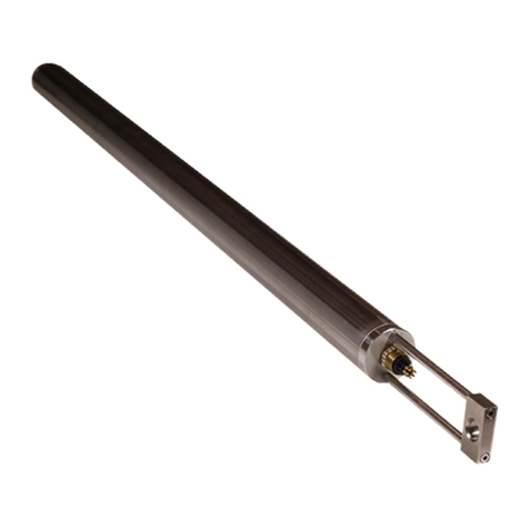
JEWELL JD Series User manual

JDx QUICK START GUIDE
Q S 8 7 9 8 3 8 , R E V A . 6
JDx Series
User Guide
850 Perimeter Road
Manchester, NH 03103
Phone: 603–669-6400
Fax: 603–622-2690
www.jewellinstruments.com
Copyright © 2019 by Jewell Instruments LLC. All rights reserved.

JDx QUICK START GUIDE
i | P a g e Q S 8 7 9 8 3 8 , R E V A . 6
REVISION HISTORY
Revision Date Change Description
A 6/21/17 Production release
A.4 7/27/17 Relative Zero command detailed
“;000,Q,Q” Query Summary command documented
Fifo flush – “V” command note added
A.5 8/28/17 Adding Modbus notes
New parity error “strict” vs. “ignore” paradigm
Adding “Rolling Average” functionality
A.6 4/18/2019
Removed extraneous Modbus Notes, Parity Update.

JDx QUICK START GUIDE
ii | P a g e Q S 8 7 9 8 3 8 , R E V A . 6
TABLE OF TABLES ................................................................................................................................................................... iii
MANUAL ACRONYMS & NOTATIONS ..................................................................................................................................... iv
1 OVERVIEW ....................................................................................................................................................................... 1
2 INSTALLATION ................................................................................................................................................................. 1
2.1 Mechanical Connections ......................................................................................................................................... 1
2.2 Mechanical Installation ........................................................................................................................................... 2
2.3 RS-485 Installation .................................................................................................................................................. 2
2.4 Galvanic Isolation & JDx Grounding & Transient Protection .................................................................................. 2
3 JDx COMMUNICATION PROTOCOLS ............................................................................................................................... 3
3.1 Default Communication Settings ............................................................................................................................ 3
3.2 Firmware Commands & Protocols .......................................................................................................................... 3
3.2.1 General Command Formats ............................................................................................................................ 4
3.2.2 Get Value ......................................................................................................................................................... 5
3.2.3 Streaming ........................................................................................................................................................ 6
3.2.4 Sensor Node ID, Address ................................................................................................................................. 7
3.2.5 Bandwidth ....................................................................................................................................................... 8
3.2.6 Change Baud Rate ........................................................................................................................................... 9
3.2.7 Decimation .................................................................................................................................................... 10
3.2.8 Non-Volatile Save .......................................................................................................................................... 10
3.2.9 Non-Volatile Restore ..................................................................................................................................... 11
3.2.10 Query ............................................................................................................................................................. 11
3.2.11 RS-485 Termination....................................................................................................................................... 12
3.2.12 Data FIFO Query ............................................................................................................................................ 13
3.2.13 Data FIFO Dump ............................................................................................................................................ 13
3.2.14 Data FIFO Flush ............................................................................................................................................. 13
3.2.15 Bus Scan ........................................................................................................................................................ 14
3.2.16 Soft Reset ...................................................................................................................................................... 14
3.2.17 Relative Zero ................................................................................................................................................. 15
3.3 Data Integrity, CRC ................................................................................................................................................ 15
3.4 Shared RS-485 Bus ................................................................................................................................................ 15
APPENDIX A: WARRANTY & LIMITATION OF LIABILITY ........................................................................................................ 16

JDx QUICK START GUIDE
iii | P a g e Q S 8 7 9 8 3 8 , R E V A . 6
TABLE OF FIGURES
Figure 1: JDx Outline & Dimensions ....................................................................................................................................... 2
TABLE OF TABLES
Table 1: JDx Series DB9 Pinout ............................................................................................................................................... 1
Table 2: JDx Series Default Communication Settings ............................................................................................................. 3
Table 4: JDx Bandwidth vs Baud............................................................................................................................................. 8

JDx QUICK START GUIDE
iv | P a g e Q S 8 7 9 8 3 8 , R E V A . 6
MANUAL ACRONYMS & NOTATIONS
JDI Jewell Digital Inclinometer
JDA Jewell Digital Accelerometer
JDx JDI or JDA Sensor
0x__ 0x indicates hexadecimal notation
CR Carriage Return, hexadecimal 0x0D
LF Line Feed, hexadecimal 0x0A (also known as a new line)
CRLF Abbreviation for the line termination sequence “Carriage Return & “Line Feed”
CRC16 16-bit cyclic redundancy check
| “pipe” is used to separate parameters in a list of options in the firmware commands. The user should
select one parameter only.

JDx QUICK START GUIDE
1 | P a g e Q S 8 7 9 8 3 8 , R E V A . 6
1 OVERVIEW
This quick start guide covers the installation and operation of all models of the Jewell Digital Inclinometer. The inclinometer
provides continuous dual axis measurements of inclination via ASCII over RS-485 over the sensor’s linear range with
resolution down to 0.001 degree. Power is supplied through two pins on the DB9 connector.
The sensors are shipped with generic settings and the intention is that the user will reconfigure the sensor to meet the
needs of their RS-485 bus if the sensor will co-exist with other RS-485 devices. For large quantity orders we are happy to
reconfigure the sensors however you see fit (programming charges may apply).
2 INSTALLATION
The following sections cover mechanical connections and mechanical installation.
2.1 MECHANICAL CONNECTIONS
The inclinometer comes fitted with an IP67 rated male DB9 connector. In order to achieve the full IP67 rating, an
appropriate mating connector with an IP67 rated backshell must be employed and fully engaged. IP67 backshells are
readily available from suppliers such as NorComp, Conec and Digi-Key.
The pinout for the JDx sensor is provided below.
Table 1: JDx Series DB9 Pinout
9-PIN CONNECTOR
PIN ASSIGNMENT
1 (-), [RS-485]
2 (+), [RS-485]
3 N/C
4 N/C
5 GND, [RS-485]
6 N/C
7 N/C
8 PWR-
9 PWR+
Pins 1 and 2 are polarity specific and are used for the half-duplex RS-485 communication lines. Take note of the polarity.
Pin 5 contains the ground reference for the RS-485 lines and depending on installation may not be required.
Pins 8 and 9 are the power pins for the JDx sensor. Reverse polarity protection (via a diode bridge) has been implemented
internal to the sensors. This means either power or ground can be applied to either pin 8 or 9 without causing electrical
damage. Apply DC voltage only.

JDx QUICK START GUIDE
2 | P a g e Q S 8 7 9 8 3 8 , R E V A . 6
2.2 MECHANICAL INSTALLATION
The figures below show the hole pattern required to mount the JDx sensor. The figures also provide the dimensions of the
inclinometer. Dimensions are provided in Imperial units of inches, shown without brackets, and SI units of millimeters,
shown within brackets.
Figure 1: JDx Outline & Dimensions
2.3 RS-485 INSTALLATION
The JDx sensor may be installed on an RS-485 bus. Jewell recommends that the sensor installer review appropriate
guidelines for multiple devices on a bus. The JDx sensor contains a 120 Ω termination resistor at the PCB level near the
internal RS-485 transceiver. The JDx sensor is shipped with the termination resistor enabled, though the termination may be
disabled at the installer’s preference. Enabling and disabling of the termination resistor is accomplished through firmware
commands covered in Section 3.
Early versions of the JDx sensor also include biasing resistors on the A and B signals. The RS-485 (A) signal is pulled high and
the RS-485 (B) signal is pulled low to the RS-485 ground reference. Standard future revisions will not have the bus biasing
resistors installed, though they will be available for custom orders.
2.4 GALVANIC ISOLATION & JDX GROUNDING & TRANSIENT PROTECTION
Both the power connections and RS-485 connections are Galvanically isolated from the internal sensor. The power inputs
are rated to 2kVAC whereas the RS-485 connections are rated to 5kVAC. This ensures that common mode noise which may
develop over long cable lengths will not adversely affect the sensitive measurements of the device. The power and RS-485
signals are separated from each other, but their separation is not rated as a Galvanic isolation.
The shell of the DB9 has a low impedance path to the baseplate of the sensor. This ensures that cable noise is diverted
through the aluminum enclosure and into the mounting structure of the sensor.
To further protect the JDx sensor in the harshest electrical environments, all inputs and outputs have bi-directional
transorbs and gas discharge tubes to dissipate any transient energy. Further, all inputs and outputs have differential
transorbs.

JDx QUICK START GUIDE
3 | P a g e Q S 8 7 9 8 3 8 , R E V A . 6
3 JDX COMMUNICATION PROTOCOLS
The JDx sensor data is easy to retrieve from the sensor as a simple and intuitive protocol has been implemented. To obtain
this data, a simple terminal emulation program1 (or equivalent) may be used on the system/computer side. The sections
below outline the communication settings, firmware commands, and protocols. The JDX supports a proprietary ASCII
interface protocol.
3.1 DEFAULT COMMUNICATION SETTINGS
The defaults for the communication settings are listed below. Of the settings shown below, only the baud and parity may be
changed.
Table 2: JDx Series Default Communication Settings
Baud
19200
Data Bits
8
Parity
Even
Stop Bits
1
Flow Control
None
3.2 FIRMWARE COMMANDS & PROTOCOLS
The firmware commands and protocols are provided in the sections below.
1 RealTerm Serial Capture Program, or HyperTerminal are example programs.

JDx QUICK START GUIDE
4 | P a g e Q S 8 7 9 8 3 8 , R E V A . 6
3.2.1 GENERAL COMMAND FORMATS
Jewell ASCII command protocol conforms to a basic format as described in the following section(s).
3.2.1.1 PROPRIETARY ASCII
Commands are packets transmitted from the “master” to the “slave.” The slave is always the JDx sensor – it provides the
response. For the JDx sensor to acknowledge a command, the data packet must either start with a : (colon) or ; (semicolon)
and end with a CR (0x0D) and LF (0x0A). Without the “:”, “;”, or CRLF2, the JDx sensor will not respond. Very generically, the
commands must have the following syntax:
;<NodeID>,<Command>,<Parameter>CRLF
:<NodeID>,<Command>,<Parameter>,<CRC16>CRLF
Please take note that above there are two commands shown. One begins with a colon, and the other begins with a
semicolon. Commands which begin with a semicolon will not invoke the 16-bit CRC check within the device. Commands
which begin with a colon must include a 16-bit CRC and the JDx will enforce CRC checking. The latter implementation allows
the JDx sensor to check data packet integrity in noisy environments. It is up to the discretion of the user to implement one
or the other.
Please also take note of the commas and the NodeID. The commas allow packets to be easily parsed and each packet must
contain a NodeID. If the NodeID transmitted by the master does not match the NodeID of the target JDx sensor, then the
target sensor will ignore the command3.
All commands in the following sections must be issued using ASCII text only.
3 The JDx will respond to the broadcast address of “000”. This is intended for ease of recovery, configuration and setup and is not
intended for general use in the field. If multiple units are on the same bus their responses to a broadcast command will generally have a
data collision.

JDx QUICK START GUIDE
5 | P a g e Q S 8 7 9 8 3 8 , R E V A . 6
3.2.2 GET VALUE
This command obtains the most recent sample from the JDx sensor. This command is useful when the JDx sensor is installed
on a shared RS-485 bus and the user wishes to implement the JDx sensor as a true slave device. The last parameter before
the CRC is a 16-bit sequence number. Every time a data point is generated by the sensor the sequence number is
incremented. This will allow downstream software to know if it has read the same data point twice, or if it has missed a data
point. (See also FIFO commands, specifically section 3.2.13)
Command Syntax ;<NodeID>,VCRLF or
:<NodeID>,V,<CRC16>CRLF
Response Syntax Varies per “sample type”, reflecting the sensor configuration purchased4.
<NodeID>,V,41,<X G’s >,<Temperature>,<seq>,<CRC16>CRLF
<NodeID>,V,42,<X G’s>,<Y G’s >,<Temperature>,<seq>,<CRC16>CRLF
<NodeID>,V,43,<X G’s>,<Y G’s >,<Z G’s >,<Temperature>,<seq>,<CRC16>CRLF
<NodeID>,V,51,<X angle>,<Temperature>,<seq>,<CRC16>CRLF
<NodeID>,V,52,<X angle>,<Y angle>,<Temperature>,<seq>,<CRC16>CRLF
Example Command ;001,VCRLF
Example Response 001,V,52,+16.0396,+0.0117,+22.050,2559,E007CRLF
Note Sample type for the JDI-200-5/5-5293 was “7”, this has been promoted to “52” to align with
our standard part offerings.
X and Y angular values are in degrees, Temperature is in degrees Celsius and <CRC16> is
reported in hexadecimal.
Sequence number is an unsigned 16-bit number and will rollover from 65535 to 0.

JDx QUICK START GUIDE
6 | P a g e Q S 8 7 9 8 3 8 , R E V A . 6
3.2.3 STREAMING
This command enables the JDx sensor to continuously transmit data out to the RS-485 bus at the bandwidth specified in
section 3.2.5. A value of 0 or 1 must be provided. The value of 0 turns off data streaming, while the value 1 enables data
streaming. This command is useful if the user wishes to not actively interrogate the JDx sensor for samples. Care should be
taken using this command when the JDx sensor is installed on a shared RS-485 bus.
Command Syntax ;<NodeID>,S,<1|0>CRLF or
:<NodeID>,S,<1|0>,<CRC16>CRLF
Response Syntax <NodeID>,S,<0=OFF, 1=ON>,Streaming,<CRC16>CRLF
(Subsequent data points will adhere to the “V” command’s syntax, see section Error!
Reference source not found.)
Example Command ;009,S,1CRLF
Example Response 009,S,1,Streaming,F465CRLF
009,V,7,+2.9175,-0.3806,+17.620,20,ACA9CRLF
009,V,7,+2.9182,-0.3804,+17.618,21,7B87CRLF
009,V,7,+2.9190,-0.3806,+17.618,22,E773CRLF
Note A Non-Volatile Save command is required to save the streaming setting to non-volatile
memory. This will ensure the parameter is recalled after a power cycle. Responses to the
commands are the same as the responses to the Get Value command.
Changing the baud or the output data rate of the device may interrupt the stream. If this
occurs, simply re-issue the command to start streaming with the new settings.

JDx QUICK START GUIDE
7 | P a g e Q S 8 7 9 8 3 8 , R E V A . 6
3.2.4 SENSOR NODE ID, ADDRESS
This command changes the NodeID, or bus address of the JDx sensor. Each JDx sensor is shipped from the factory with a
default NodeID, corresponding to the last two digits of the specific sensor’s serial number. Changing the address is very
simple if the user wishes to assign something other than the factory default. Any integer value from 1 to 250 is accepted.
Command Syntax ;<NodeID>,A,<New_NodeID>CRLF or
:<NodeID>,A,<New_NodeID>,<CRC16>CRLF
Response Syntax <NodeID>,A,<New_NodeID>,Address,<CRC16>CRLF
Example Command ;001,A,2CRLF
Example Response 002,A,002,Address,<CRC16>CRLF
Note A Non-Volatile Save command is required to save the new NodeID to non-volatile memory.
This will ensure the parameter is recalled after a power cycle. <CRC16> is reported in
hexadecimal.
The default ID is generally the last two digits of the serial number. As zero is disallowed,
sensors with a serial number ending in “00” will be programmed to have an ID of “100”
instead.

JDx QUICK START GUIDE
8 | P a g e Q S 8 7 9 8 3 8 , R E V A . 6
3.2.5 BANDWIDTH
This command changes the output data rate (aka data sample rate) of the JDx sensor. The table below shows the
combinations which are allowed vs the baud rate. Care must be taken in selecting the bandwidth of the sensor and the
baud of the sensor. For obvious reasons, the user should not select the highest output data rate and lowest baud setting.
Table 3: JDx Bandwidth vs Baud5
Bandwidth (
Output Sample Rate
)
Baud
3.9
7.8
15.6
31.2
62.5
125
300
X
X
X
X
X
X
9600
OK
OK*
X
X
X
X
19200
OK
OK
OK*
X
X
X
38400
OK
OK
OK*
X
X
X
57600
OK
OK
OK
OK*
X
X
115200
OK
OK
OK
OK
OK*
X
500000
OK
OK
OK
OK
OK
OK*
Command Syntax ;<NodeID>,B,<3.9|7.8|15.6|31.2|62.5|125>CRLF or
:<NodeID>,B,<3.9|7.8|15.6|31.2|62.5|125>,<CRC16>CRLF
Response Syntax <NodeID>,B,<NewDataRate>,Data rate,<NewBW>,-3dB,<CRC16>CRLF
Example Command ;001,B,15.6CRLF
Example Response 001,B,15.6,Data rate,3.9,-3dB,2258CRLF
Note A Non-Volatile Save command is required to save the new New_Bandwidth to non-volatile
memory. This will ensure the parameter is recalled after a power cycle. The sensor will
round to the nearest data rate that it is capable of providing. The filter’s -3dB point is ¼ of
the sample rate and is also echoed for clarity. <CRC16> is reported in hexadecimal.
Bandwidth may be reduced by the “Data Averaging” setting, see also section 3.2.7
5 Combinations with a “*” denote configurations that are possible, but subsequent communications will likely need to be retried as the
bus bandwidth is nearly full.

JDx QUICK START GUIDE
9 | P a g e Q S 8 7 9 8 3 8 , R E V A . 6
3.2.6 CHANGE BAUD RATE
This command changes the baud rate of the JDx sensor. Each JDx sensor is shipped from the factory with a default Baud of
19200 bps. The baud value must be an integer between 300 and 500,000. Please note that the streaming feature is only
supported above 9600 baud. Parity may be set with the case-insensitive first letter of the parity desired, e.g., ‘e’ven, ‘n’one,
or ‘o’dd. Supported baud rates6 are 500000, 115200, 57600, 38400, 19200, 9600 and 300. These baud rates all have less
than 1.6% baud error.
Command Syntax ;<NodeID>,C,B,<300| 9600|19200|38400|57600|115200|500000>,<E|N|O>CRLF
:<NodeID>,C,B,< 9600|19200|38400|57600|115200|500000>,<E|N|O>,<CRC16>CRLF
Response Syntax <NodeID>,C,B,<New_Baud>,8<parity>1,1 sec delayed baud change,<CRC16>CRLF
<NodeID>,C,B,<New_Baud>,8<parity>1,New baud,<CRC16>CRLF
Example Command ;001,C,B,115200,nCRLF
Example Response 003,C,B,115230,8n1,1 sec delayed baud change,01F1CRLF
003,C,B,115230,8n1,New baud,F98A001,C,B,115200,8n1,New baud,D511CRLF
Note A Non-Volatile Save command is required to save the new “New_Baud” baud to non-volatile
memory. This will ensure the parameter is recalled after a power cycle. The first response
line is sent at the old baud rate, the second line is sent at the new baud rate. There is a 1.0
±0.2 second delay from the start of the first line’s transmission to the start of the second
line’s transmission. <CRC16> is reported in hexadecimal.
Switching from baud rates below 9600, the first line may not completely print before the 1.0
sec time expires. The JDx will respond with the closest achievable baud to your requested
rate.

JDx QUICK START GUIDE
10 | P a g e Q S 8 7 9 8 3 8 , R E V A . 6
3.2.7 DECIMATION
NOTE: This command is intended only for cases where the desired data rate is below 4Hz. (Geophysical/geotechnical
monitoring, etc.)
This command changes the output data rate by decimation. Each JDx sensor is shipped from the factory with a default
averaging of 1 sample, i.e, no averaging. The JDx sensor will average the specified number of samples prior to transmitting
data on the RS-485 bus. When changing to new values, the value must be an integer and be in the range of 1 to 4096
samples.
Command Syntax ;<NodeID>,D,<New_Average>CRLF or
:<NodeID>,D,<New_Average>,<CRC16>CRLF
Response Syntax <NodeID>,D,<New_Average>,Samples to average,<CRC16>CRLF
Example Command ;001,D,2000CRLF
Example Response 001,D,2000,Samples to average, 2998CRLF
Note A Non-Volatile Save command is required to save the new New_Average to non-volatile
memory. This will ensure the parameter is recalled after a power cycle. Sample data rate
will be affected by this value. <CRC16> is reported in hexadecimal.
3.2.8 NON-VOLATILE SAVE
This command saves the current settings of the JDx sensor to non-volatile memory. The non-volatile save command should
be issued when the user wishes to save the changed parameters to ensure those settings are recalled upon power up. If this
command is not issued after parameters are changed, the JDx sensor will revert back to its previous settings on the next
power up.
Command Syntax ;<NodeID>,N,SCRLF or
:<NodeID>,N,S,<CRC16>CRLF
Response Syntax <NodeID>,N,S,Settings stored in EEPROM,<EEPROM CRC>,<CRC16>CRLF
Example Command ;001,N,SCRLF
Example Response 001,N,S,Settings stored in EEPROM,0xB97C,6290CRLF
Note EEPROM CRC is reported for informational use only, the communication CRC is not preceded
by “0x”. < EEPROM CRC > & <CRC16> are reported in hexadecimal.

JDx QUICK START GUIDE
11 | P a g e Q S 8 7 9 8 3 8 , R E V A . 6
3.2.9 NON-VOLATILE RESTORE
This command restores the JDx sensor to its last saved settings from within the non-volatile memory. The non-volatile
restore command should be issued when the user wishes to recall the previously saved settings.
Command Syntax ;<NodeID>,N,RCRLF or
:<NodeID>,N,R,<CRC16>CRLF
Response Syntax <NodeID>,N,R,Settings loaded OK,<Calc’ed CRC>,<ROM CRC>,<CRC16>CRLF
Example Command ;001,N,RCRLF
Example Response 001,N,R,Settings loaded OK,0xB97C,0xB97C,92C3CRLF
Note If there is a CRC failure, the sensor will still try to load certain values, but the baud rate will
be overridden to 19200. Calculated CRC and the CRC retrieved from the EEPROM are
reported for informational use. <Calc’ed CRC>, <ROM CRC> & <CRC16> are reported in
hexadecimal.
3.2.10 QUERY
This command queries the settings of the JDx sensor and transmits it out to the RS-485 bus for the user to review how the
JDx sensor is configured.
Command Syntax ;<NodeID>,Q,<Q|B|D>CRLF or
:<NodeID>,Q,< Q|B|D><CRC16>CRLF
where <Q|B|D> is one of the following (select one only):
Q is full report, B = bandwidth, D = data samples to average
Response Syntax Varies with query request.
Example Command ;001,Q,BCRLF
Example Response 001,Q,B,3.9,Data rate,1.0,-3dB,D042CRLF
Note The query command is intended to allow access to the responses from other commands
without having to write over the current values, e.g., “;001,Q,BCRLF“ allows the user to
access the response from the ‘B’ command without writing anything to the device. A
summary of all settings is available via a “;001,Q,QCRLF” command. <CRC16> is reported in
hexadecimal.

JDx QUICK START GUIDE
12 | P a g e Q S 8 7 9 8 3 8 , R E V A . 6
3.2.10.1 QUERY SUMMARY
A simple method to retrieve the state of almost all of the settings is to issue a “Query Summary” command.
Command Syntax ;<NodeID>,Q,QCRLF or
:<NodeID>,Q,Q,<CRC16>CRLF
Response Syntax <NodeID>,Q,Q,<ISO encoding and copyright statement>,<model>,<serial
number>,<Software Revision>,<SVNMODS>,<SW build date>,<Calibration due
date>,<Manufactured date>,<Address>,<Output
style>,<Reserved>,<Streaming>,<Reserved>,<Bus termination>,<Relative
zero>,<Reserved>,<Reserved>,<Data rate>,<Decimation>,<Baud rate>,<CRC16>CRLF
Example Command ;000,Q,QCRLF
Example Response7 027,Q,Q,<ISO 8859-1>©2017 Jewell Instruments,Factory-Use,Beta_27,SW_Rev=792,Not
modified,Built=2017/07/31 19:40:17
UTC,CalDue=2017jan01,Manufactured=2017may12,A=27,O=52,R=2,S=0,T=0,X=1,Z=0,GC=-
9.050,OC=2078.250,ODR=3.906,D=1,baud=113636,3AABCRLF
3.2.11 RS-485 TERMINATION
This command enables or disables the 120 Ω termination resistor within the JDx sensor. Each JDx sensor is shipped from the
factory with the termination resistor enabled. The value of 0 disables the termination resistor, while the value of 1 enables
the resistor. The user must ensure that on a shared RS-485 bus that only one termination resistor is installed and that it is
implemented at the distant end of the RS-485 network. Please reference section 3.4 for helpful information regarding RS-
485 networks.
Command Syntax ;<NodeID>,X,<1|0>CRLF or
:<NodeID>,X,<1|0>,<CRC16>CRLF
Response Syntax <NodeID>,X,1,RS485 termination ,<CRC16>CRLF
Example Command ;001,X,1CRLF
Example Response 001,X,1,RS485 termination,E8D6CRLF
Note <CRC16> is reported in hexadecimal.
7 Revisions older than 790 of the software will not report the baud rate

JDx QUICK START GUIDE
13 | P a g e Q S 8 7 9 8 3 8 , R E V A . 6
3.2.12 DATA FIFO QUERY
In an effort to support downstream DSP efforts, the JDx has a FIFO of up to 64 of the latest data points. As an alternative to
streaming, the FIFO may be accessed to burst data out of the sensor without needing to access it in a real-time fashion to
recover all data that it generates. The Data FIFO Query command reports the number of entries currently residing in the
FIFO. The count is accurate as of the point in time that the command was received. During the generation of the ASCII
response string and its conveyance across the physical RS-485 link, more data may have been generated.
Command Syntax ;<NodeID>,F,QCRLF or
:<NodeID>,F,Q,<CRC16>CRLF
Response Syntax <NodeID>,F,Q,<FIFO_size>,<CRC16>CRLF
Example Command ;000,F,QCRLF
Example Response 001,F,Q,27,D1C1CRLF
3.2.13 DATA FIFO DUMP
This command will create a short stream of data similar to the streaming function, but it will cease once it has emptied the
FIFO.
Command Syntax ;<NodeID>,F,DCRLF or
:<NodeID>,F,D,<CRC16>CRLF
Response Syntax <NodeID>,F,D,Dumping <N>+ entries,<CRC16>CRLF
Example Command ;000,F,DCRLF
Example Response 250,F,D,Dumping 2+ entries,85D0CRLF
250,V,R,-393,-1333,+255300,+1697,1032,2478 CRLF
250,V,R,-383,-1329,+255303,+1697,1033,9105 CRLF
3.2.14 DATA FIFO FLUSH
This command will re-initialize the FIFO. Not only will the existing data be discarded, but the sequence number will be reset
to zero. Note that the Get Value command (see section Error! Reference source not found.) will still report the last known
good values, but the sequence number will be zeroed8. The first data point calculated after the flush will be sequence
number 1.
Command Syntax ;<NodeID>,F,FCRLF or
:<NodeID>,F,F,<CRC16>CRLF
Response Syntax <NodeID>,F,F,FIFO flushed,<CRC16>CRLF
Example Command ;000,F,FCRLF

JDx QUICK START GUIDE
14 | P a g e Q S 8 7 9 8 3 8 , R E V A . 6
Example Response 001,F,F,FIFO flushed,8AFDCRLF
3.2.15 BUS SCAN
This command will cause all devices on an RS-485 bus to respond in turn allowing you to identify which addresses are
present on an unknown bus. While this will work with specific addresses, this command is intended to be a broadcast
command.
Command Syntax ;<NodeID>,*CRLF or
:<NodeID>,*,<CRC16>CRLF
Response Syntax <NodeID>,*,<CRC16>CRLF
Example Command ;000,*CRLF
Example Response 249,*,2566CRLF
250,*,7958CRLF
Note: This command has delayed responses based on the actual addresses present on the bus.
Approximate completion times are:
500000 baud, 0.205 seconds
115200 baud, 0.460 seconds
9600baud, 4.1 seconds
300 baud, 128.0 seconds
3.2.16 SOFT RESET
If for some reason you need to issue a soft reset command to the sensor, this command is available. This will not cycle
power to any portion of the sensor, but will reset the microcontroller, reload the non-volatile settings and re-initialize the
hardware.
Command Syntax ;<NodeID>,>shutdown –r nowCRLF or
:<NodeID>,>shutdown –r now ,<CRC16>CRLF
Response Syntax There is no response to this command
Example Command ;186,>shutdown -r nowCRLF

JDx QUICK START GUIDE
15 | P a g e Q S 8 7 9 8 3 8 , R E V A . 6
3.2.17 RELATIVE ZERO9
The JDx family f sensors offers you the ability to compensate for any installation offsets you may encounter. This alleviates
the majority of tolerance concerns when designing brackets or mounting surfaces for the JDx. When the command is issued
to capture a relative zero, the device will capture its next reading as the new zero point. A non-volatile save (see section
3.2.8) is required for this value to persist following a power cycle or manual reset.
Command Syntax ;<NodeID>,Z,1CRLF or
:<NodeID>,Z,1,<CRC16>CRLF
Response Syntax Varies per number of axes in your product:
<NodeID>,Z,1,<1st axis offset>,…,<CRC16>CRLF
Example Command ;027,Z,1CRLF
Example Response 027,Z,1,-74.4550,Software zero,4756CRLF (Single axis inclinometer)
027,Z,1,-74.1570,-7.2397,Software zero,547E (Dual axis inclinometer)
3.3 DATA INTEGRITY, CRC
All responses from the JDx sensor include an ASCII based 16-bit CRC value. The value is provided so that the customer may
choose to validate packet content integrity in any environment. The CRC implementation was borrowed from the CRC
calculation algorithm used by the Modbus protocol10. The CRC value is always the last 2 bytes prior to the CR and LF which
represents the last four ASCII characters of the transmitted packet.
3.4 SHARED RS-485 BUS
A helpful resource for RS-485 networks and implementation is authored by Texas Instruments11.
9 It is possible for Jewell to pre-load a relative zero into the device, please contact sales@jewellinstruments.com for details.
10 See http://modbus.org/docs/PI_MBUS_300.pdf (page marked “112”). See also https://www.libcrc.org/ specifically
https://www.libcrc.org/crc_modbus/. The JDx implements revision 69 of the “libcrc.org” code.
11 The RS-485 Design Guide, authored by Texas Instruments, http://www.ti.com/lit/an/slla272c/slla272c.pdf
Table of contents
Other JEWELL Measuring Instrument manuals