JEWELL DX Series User manual

Jewell Instruments DX Series User Manual V.81814
2
Contents
1. General Information...................................................................................................................6
A. About this Manual ..................................................................................................................6
i. Related Documentation / Applications.........................................................................6
ii. Documentation Conventions...........................................................................................6
B. Warranty ...................................................................................................................................7
2. Product Overview.......................................................................................................................8
A. Introduction to the DX Series ................................................................................................8
i. Features and Options.........................................................................................................8
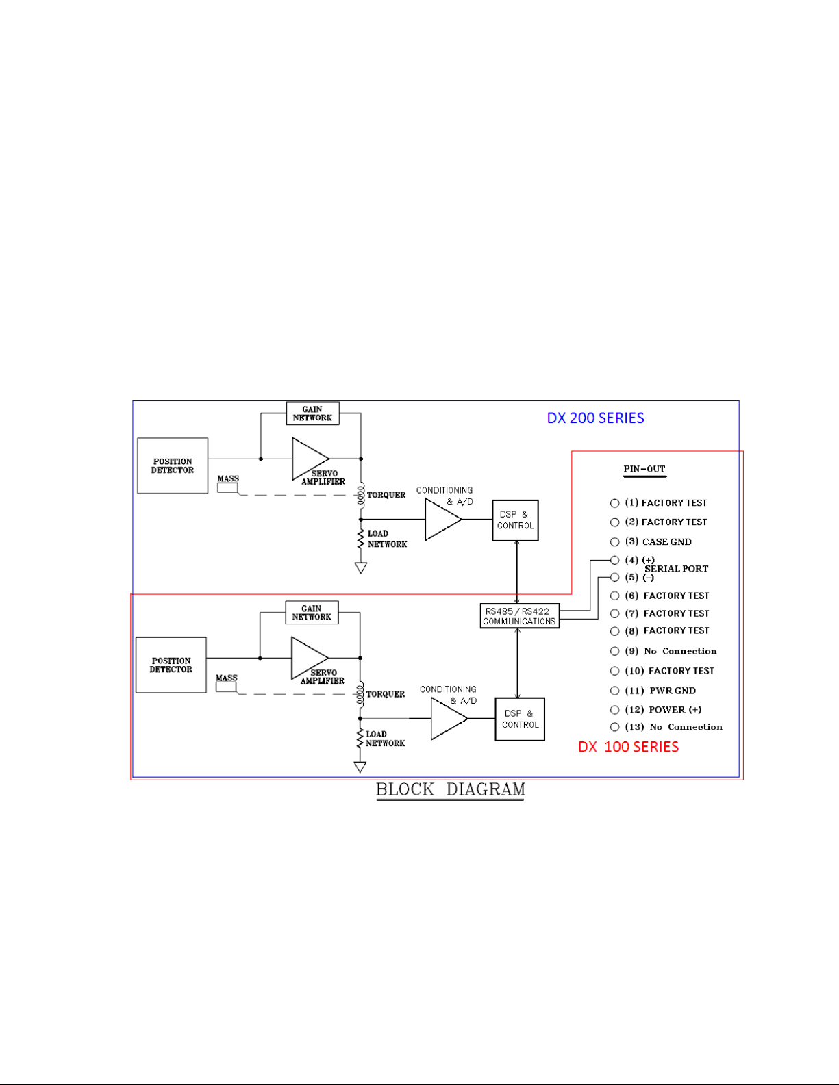
ii. Internal Diagram .................................................................................................................9
iii. Typical Applications .........................................................................................................10
B. DX Series Installation.............................................................................................................10
i. Mechanical........................................................................................................................10
ii. Electrical .............................................................................................................................12
3. Basic Operating Tenants.........................................................................................................13
A. Getting Started......................................................................................................................13
i. Default Settings..................................................................................................................13
ii. Terminal Programs.............................................................................................................14
iii. Connecting to the Serial Interface ...............................................................................14
B. Operational Modes..............................................................................................................14
i. RS422....................................................................................................................................15
ii. RS485....................................................................................................................................15
iii. Temporary RS485...............................................................................................................15
C. Serial Communications........................................................................................................16
i. Packet Structure................................................................................................................16
ii. Using DX Series Commands ............................................................................................19
4. Building Command Structures...................................................................................................20
A. Full List of Serial Commands................................................................................................21
i. Configuring Measurement Outputs ..............................................................................21
ii. Configuring Transmission Parameters ...........................................................................25
iii. Maintenance and Infrastructure Inputs .......................................................................29

Jewell Instruments DX Series User Manual V.81814
3
5. Responses from the DX Series Sensor....................................................................................36
A. ACK and NAK ...........................................................................................................................36
B. 7 Byte Measurement Output .................................................................................................37
i. DXI Decoding.....................................................................................................................38
ii. DXA Decoding...................................................................................................................40
6. Additional Information.............................................................................................................44
A. Errors and Flash Memory Verification ...............................................................................44
B. Troubleshooting.....................................................................................................................45
C. Guidelines and Effective Output Rate Selection ...........................................................46
D. Mounting Considerations....................................................................................................46
E. Line Resistance Effects.........................................................................................................47
Appendix A: Condensed Command Set ...................................................................................48
1. Measurement Outputs.........................................................................................................48
2. Transmission Parameters......................................................................................................50
3. Maintenance & Infrastructure............................................................................................52
Appendix B: Technical Documentation......................................................................................55

Jewell Instruments DX Series User Manual V.81814
5

Jewell Instruments DX Series User Manual V.81814
6
1. General Information
This section will provide general notes and conventions about the product, its
manual, and any other resources which may be available for assistance.
A. About this Manual
This manual will cover the installation and operation of a Jewell Instruments DX
Series force balance digital sensor. Topics will include Operations, Specifications,
Product Information, Best Practices, and more, all related to the DX Series sensor. In
order to best understand the DX Series Sensor it is recommended to place the Unit
under evaluation conditions and preform commands simultaneously with the user’s
guide.
i. Related Documentation / Applications
In addition to this manual there are additional resources that are available for
interfacing with your DX Series Unit. The two additional resources in addition to the user
guide would be:
•DX Series Quick Start Guide
•DX Series Interface Platform Application
The DX Series Quick Start Guide is an abbreviated version of this manual for fast set up
time providing only the minimum of information in order to begin operation with the DX
Series Unit. It should not be used as a substitute for this document however could prove
useful for those new to the unit or where a reminder set of information is helpful.
The DX Series Interface Platform is a pre-packaged Labview application/vi which
automates most of the functionality of a DX series into a GUI for simple operation. The
Interface Platform is available for distribution via the Sales Department of Jewell
Instruments or your local distributor at no cost. Please contact the distributor or Jewell
Instruments Sales at 603.669.6400.
ii. Documentation Conventions
Throughout this manual certain language or mathematical conventions will be used in
order to accurately represent and evaluate outputs. These conventions may break
traditional grammar and spelling behaviors, including abbreviations, bitwise and
hexadecimal representation with prefixes, etc…
•Hexadecimal notation for inputs and outputs is shown throughout this manual will
be shown by a leading ‘$’ or ‘0x’ prefix followed by the MSB. Binary inputs will be
designated as ‘0b’ followed by the binary output MSB first.
Example: 0xA6 = $A6 = [0b1010 0110]

Jewell Instruments DX Series User Manual V.81814
7
•C programming language conventions are used in this manual to give practical
decoding examples.
•RS485 Transmission protocol and the corresponding RS485 operational mode are
referred to as 485. The same convention is used for RS422 and the corresponding
RS422 Operational Mode as 422.
•The use of words and phrases which have an underline refer to executable
commands for which further information is provided. They will most be used in the
Operations section of this manual as well as Appendix A: Condensed Command
List.
Example: “In order to switch from 485 to 422 preform a RESET after saving to flash
with the DX series unit in the correct operational mode
•When referring to the DX Series Model for communication, installation, or other
functions the following alternative words and phrases may be used: UUT (Unit
Under Test) , DUT (Device Under Test), DX Series Unit/Sensor.
•When referring to the Labview VI, Computer Application, PC, or other receiving
body which is the primary destination for data from the DX Series device the
following words and phrases may be used: Host, Terminal, Function, Application,
Program.
B. Warranty
Seller warrants its products to be free from defects workmanship and material.
Seller’s liability is limited to replacing the instrument, or any part thereof, that is returned
by the original purchaser, transportation paid, to the factory within on (1) year after
date of shipment, provided that the Seller’s examination shall disclose that a defect
existed under proper and normal use. Seller shall not be responsible for consequential
damages of any kind. This warranty is in lieu of all other warranties, liabilities or
obligations to the Buyer or any other person.

Jewell Instruments DX Series User Manual V.81814
8
2. Product Overview
The DX series is a Force Balance based approach to acceleration and inclination
detection. It builds upon the established force balance servo based sensing system
Jewell Instruments is known for and adds a digital backend for enhanced functionality.
It utilizes a dedicated microcontroller for individual axis control, as well as error
detection and multiple unit installation on a single bus.
A. Introduction to the DX Series
The DX Series by Jewell Instruments is comprised of Digital Accelerometers and
Inclinometers. The sensors can have either single or dual sensitive axes on a single
digital output bus. Each unit’s analog front end works with the digital interface to
produce data in one of two transmission modes which communicate via a 2-wire
differential line. When using RS485 protocol (default) operating in half duplex each unit
is capable of 2 way communication. In the inverse configuration the unit is operating in
an emulated RS422 mode, more about this in the Operating modes. Transmissions to
and from the device are in a custom binary format which require encoding and
decoding for each operation or output. The output type of the unit is in either
thousandths of a degree (DXI) or a fractional acceleration (DXA) format as outlined in
each sub-section of this document DXA/DXI Decoding.
In addition to those digital characteristics each unit can take a wide single
supply range of 10V to 30V. The unit connects to external sources by a 13 pin locking
barrel plug; more information can be found in the Mechanical section. By default DX
Series units are shipped in the following configuration: RS485, 38.4k Baud Rate, with No
Averaging, Normal Polarity.
i. Features and Options
The DX series sensor enhances the capabilities of the standard servo output of
our other product offerings. Each DX series unit has the capability of adjusting several
out its output, transmission and data manipulation characteristics to best suit each
individual application. In addition to the standard series of features each DX series
model has a CENELAC / AREMA Model. The type “–R” models CENELAC and AREMA
model is qualified for the following abbreviated standards:
CENELEC EN 55022:2010

Jewell Instruments DX Series User Manual V.81814
9
CENELEC EN 50155:2007
CENELEC EN 61000-4-8:2010
AREMA Part 11.5.1
For the complete test plan and results please contact Jewell Instruments Sales
Department.
ii. Internal Diagram
The core of the DX Series is based on the same force balance sensors which drive
Jewell’s analog sensor offerings. This front back end consists of a torquer, servo, position
detector, and various signal conditioning circuits. The analog back end then is fed into
the microcontroller and control system as shown in the following Figure 1: DX Series Top
Level Hardware Block Diagram.
Figure 1: DX Series Top Level Hardware Block Diagram
Note: The analog / digital relationship is one way as the DSP does not actively modify
the analog back end. It does however play a role in the conditioning and A/D sub-
circuit.

Jewell Instruments DX Series User Manual V.81814
10
iii. Typical Applications
The Jewell instruments DX series is suited for a wide range of applications and
functions. Its differential line transmission allows for greater distance from unit to host
and vice versa. For DXA/DXI applications we recommend it for the control and
monitoring of the following types of systems:
Radar/Antenna
Structural
Linear Acceleration and Deceleration
Automatic Train Position
Seismic
Platform Leveling
Of course the applications for the DX series are not limited to these fields, but have
potential anywhere a linear acceleration or incline needs to be accounted for.
B. DX Series Installation
This section will cover the electrical and mechanical installation of the DX Series
digital senor. It will provide diagrams and other illustrations to assist in the initial physical
setup of the sensor. All functional elements of the unit including communication,
operating modes, and decoding will be covered in the Operations section of this User
Guide.
i. Mechanical
The DX series was designed for maximum compatibility with the Jewell
Instruments LCF-2330 Sensor therefore it uses the same form factor and dimensions. It is
a sealed unit with a military style locking barrel plug and an IP rating of 67. In addition
to its static response, the sensor is designed to resist corrosion and is unit is rated to IP67
and 1500g, 1msec, ½ sine shock tolerance.
1. Matting Connectors
The standard connector on any DX series model is a 13 pin locking barrel plug
with male pins, model type: MS27476Y10D35P.

Jewell Instruments DX Series User Manual V.81814
11
The interlocking female inverse for the unit’s connector is: MS27473T10B35S or
equivalent based on the specific application. The exterior of the unit is non-conductive
however each housing on the connector.
2. Unit Dimensions
The sensor is tightly packed within the enclosure to allow for the smallest
footprint. Below you can see a partial engineering drawing and its dimensions
for the DX series unit.

Jewell Instruments DX Series User Manual V.81814
12
3. Alignment Surfaces
In order to achieve the most accurate results from your DX series unit, mounting should
be done with reference to the reference alignment edge. Those surfaces are used to
define the calibration and are recommended as a best practice for your DX series unit.
ii. Electrical
The DX Series operates from a single positive supply voltage from 10-30 V with
average current consumption of approximately 50mA for DX-200 series models.
Connections should be made via shielded cable having a twisted pair for the Serial
I/O leads for maximum noise isolation. Non-twisted pair cabling can be used in
applications with lower point to point transmission distances. The shield should be
connected to Case Ground at the device end. To avoid creating a ground loop, if
there is continuity or a voltage difference between the device case and the chassis of
the RS422/RS485 adaptor at the Host end, the shield should be left unconnected at that
end. In noisy electrical environments, a clamp-on Ferrite sleeve (common-mode
choke) suitable for the cable used is recommended at the device end of the cable.
Good EMI-preventive wiring practice is to route the cable along conductive structures
so as to minimize the area enclosed by the cable and other paths between the Device
and the Host. A line termination resistor matching the Z0of the twisted-pair is needed at
the Host end. If RS485 mode is used, the Device end must likewise be terminated. If
RS422 mode is used, the device end does not require a termination resistor. However,
installing one there will ensure communications integrity should the need arise to send
the device commands to change the configuration settings.
A bias network is commonly used in RS485 installations to maintain the line at Mark
level when no node is transmitting. The DX series does not require bias, but your RS485
adaptor might –follow the recommendations given for the adaptor.
1. Wiring
The standard wiring for a DX a series consists of 5 of the 13 pins. The remaining
are used for factory test / unpopulated and should remain connection free to
ensure proper operation of the DX series. For CENELAC/AREMA Type R DX series
units, Pin 3 is unpopulated and a no connect in order to comply with standards.

Jewell Instruments DX Series User Manual V.81814
13
2. Power Supply Requirements
The best power supply for the DX series is a linear supply set to any voltage within
its operating range of 10 to 30V (Single Sided). Switching power supplies will work as
well however it may produce additional noise on the output lines, this noise in most
cases will be insignificant. Theoretically each DX unit can be run from a set of batteries
which meet the minimum voltage requirements when near depletion. This scenario has
not been tested and no resulting effects have been documented.
3. Basic Operating Tenants
The Operations section is going to cover the general operating principals of the DX
series, operational modes under which your DX Series can function, output
configuration options and non-format functionality. In addition to the different
operational modes and transmission protocols, the DX 200/100 Series offers more
functionality that can be used in order to customize the unit to its specific application.
The modifiable parameters can be made to adjust the measurement output,
transmission parameters, and maintenance based effects.
A. Getting Started
The factory default for any DX series is 485. This mode’s primary characteristic is a
need to send input to the unit to enact change or receive data as a response to query.
Therefore upon initial installation the DX series will not be transmitting until otherwise
engaged by the user. The quickest test of the DX unit is a Poll command which will
return a 7 byte data packet or an ENQ which will return a “hello world” equivalent to a
terminal emulator. The DX Interface platform can be used to quickly automate and
configure a unit without binary encoding/decoding.
i. Default Settings
By default, each unit is shipped in the following configuration:
Pin
Function
3
Case Ground
(N/C on R type models)
4
[D+] / [Serial I/O+]
5
[D-] / [Serial I/O-]
11
Supply Return
12
Supply V+

Jewell Instruments DX Series User Manual V.81814
14
Operating Mode: RS485
Baud Rate: 38400 Baud
Output Rate: 90 Hz/60 Hz (DXA/DXI)
Parity Bit: None
Character Length: 8 bits
Stop Bit: 1 Stop Bit
Averaging: None
Polarity: Normal
ii. Terminal Programs
In order to avoid writing an application from scratch when not using the DXI-DXA
Interface Platform programs, several terminal programs are available to quickly and
efficiently communicate with a unit in a binary/hexadecimal format. Jewell Instruments
LLC did not develop these programs and are not in charge of maintenance. Terminal
programs we recommend are below:
Program Name
Source
Cost/License
Realterm
realterm.sourceforge.net
Free
Docklight V2.0 (Evaluation Copy)
docklight.de
Free Evaluation Edition
With any 3rd party software there are limitations to the capabilities. But these have
been used in the development and troubleshooting of the DX series in the past so they
have some of the key features required for communication and troubleshooting. The
‘$’ hexadecimal notation was based on the realterm standard procedure for inputs.
iii. Connecting to the Serial Interface
The serial interface can be integrated into an embedded system or connected directly
to a terminal interface. With all serial interfaces make sure the logic levels are
compatible with all equipment on the bus to prevent damage to the master as well as
all slaves. Pin outs and electrical diagrams are within the electrical subsection of the DX
series installation section. If you are having trouble communicating with the unit, one of
the first things to check is the differential lines to ensure their polarity is not reversed in
error.
B. Operational Modes
Under normal operating conditions the DX series only operates in one of 3
operational modes: RS-422, RS-485, or Temporary RS-485. Both RS-422 and RS-485 are
permanent modes; they will remain the active mode until otherwise intentionally
switched. The Temporary RS-485 operational mode is an intermediary that can be
activated in a unit which is already set to RS 422 operational mode. These transmission
modes dictate method of retrieving and inputting data into the device. The operational
modes for the unit are primarily controlled through the RS-422 Emulation parameter and

Jewell Instruments DX Series User Manual V.81814
15
can only be changed in one of the two RS-485 modes. In short, the DX series unit
always starts in RS485 mode while it loads parameters and preforms memory checking
functions. After a period of about 30mS, the unit completes its startup routine and
determines if it should be operating in RS422 mode. If so it shuts down its Rx ports and
begins to send data immediately. Once the unit enters this emulated 422 state it does
not have an escape routine and will not respond or otherwise react to any other action
on the serial line. In order to escape the 422 operational modes, the unit must be issued
a break command, more on this later in the Using DX Series Command subsection.
i. RS422
In the RS-422 operational mode, each unit is sends data periodically from its
axis/axes without being polled, and the serial line is never floating. For a DX 200 unit it
will send at an output iteration will be a Twin packet that corresponds to the same
approximate time interval. In RS-422 mode the default output rate is 90Hz per axis for
DXA models and 60Hz for DXI Models at all baud rates. The low pass filter is tuned to
30Hz in most DX Models. Exceptions include the 1° and 3° DXI models, in which filter is
targeted at 3Hz and 6Hz respectively. The output sample rate can be decreased via
input commands while in one of the RS-485 modes. Installing multiple units operating in
RS422 mode on the line has a high probability to create data collisions and such a
setup is not recommended.
ii. RS485
In the RS485 operational mode, a unit only sends data when polled at its unique
address. These unique addresses allow for up to 30 units on a single bus; and each poll
command sent can request data from either X, Y, or both axes. In the event that 2 units
on the bus have the same address both will respond and the risk of collision is high. In
addition, should the two packets arrive successfully the packets will be non-
differentiable to the originating sensors.
In the case that data from both axes are requested, the unit sends a Twin
Packet. A Twin Packet consists of data from both axes send sequentially, without
releasing the line. After the Twin Packet completes the unit releases the differential line.
Twin Packets do not necessarily correspond to the same time interval but rather the
most recent calibrated digital filter output. While in the RS-485 operational mode, the
unit is capable to change any of the operating parameters via input commands.
iii. Temporary RS485
In the temporary RS485 operational mode, the unit behaves identical to
“normal” RS485 mode with one exception. A unit which was placed in temporary RS485
mode from RS422 and then is either RESET or power cycled it will default to RS422
immediately unless Emulation was turned off and saved to flash. In addition temporary
RS485 mode is not reachable when a unit is initialized in “normal” RS485 mode. The

Jewell Instruments DX Series User Manual V.81814
16
break command can be applied but it will have no effect on the unit’s behavior.
Below is a flow chart containing the operational modes relationships along with outside
influences.
RS-422
Operation
Start Up
Is RS-422
Emulation
Turned On?
Yes
RS-485
Operation
No
28 mS
Start-Up
Window
Was the BREAK
Command
Received?
While in startup Window
No
Temporary
RS-485
Operation
Yes
RESET
C. Serial Communications
The DX series uses a fixed serial protocol type compatible with RS-232/COM port
communication on desktop PC systems. Mark Level is asserted slightly more than 1
character time before the start of a transmission to allow any false start bit due to
switching the driver on to clock out of the receiving UART. See default setting in the
previous section for configuration details.
i. Packet Structure
The generalized data packet is as follows, however this structure varies in length
based on the data being sent or received. Below is a brief explanation of each portion
of the data packet for purpose, range of length, and calculation.
| Prefix | UAID | Content (arguments, data, etc...) | Checksum |
All packets to and from the device, follow this format. Prefix, UAID, and Checksum are
always one byte in width. The Content Byte(s) are of varying length and contain all
functional elements of commands or outputs. The Content bytes can be 0 bytes wide.
In DX 200 series units, the name given to dual axis information requested via a single
unified command or output iteration is called a Twin Packet.
1. Prefix/Sync
The 1st byte is known as the Prefix/Sync; this byte serves two purposes it indicates
the packet type and serves as a sync byte. It is always a variation of $A_ and the
second nibble is determined by data length.

Jewell Instruments DX Series User Manual V.81814
17
The set of Prefix values {$A0, $A3, $A6} is reserved for messages from the unit.
$A0: Variable Length
$A3: 4 Byte Response
$A6 7 Byte Response / Measurement Output Packet
The set {$A9, $AC, $AF} is reserved for messages from the master to the unit.
$A9: Short Command / Poll / 3 Byte Command
$AC: Long Command / 4 Byte Command
$AF: Extended Command / 5 Byte Command
In output only driven operation (485), only the $A9 (poll) and $A6 (data) packets are
involved. The remainders are for the command and response sets. All types except
$A0 have fixed packet lengths. $A0 packets have variable length and the 3rd byte’s
value or first byte of the content bytes is the total length of the packet.
2. UAID
UAID is the unit/axis address and is always the second byte in the sequence. In
packets from the device, b0 always indicates the X axis and b1 the Y axis. A command
to the device may be addressed to either or both axes (Adress+b1+b0) according to
b0 and b1. A command addressed to no axis, will result in no action being performed
by the unit. The UAID is never more than 1 byte in length.
If the unit is configured as RS422, the UAID byte serves mainly to identify the axis;
given the com port will be dedicated to the one constantly streaming unit. The initial
device address field is $70 (8 bit left aligned) or $1C (right aligned). Thus, if unit has
never been assigned a new address, the default UAID for X-axis is $71 and the default
UAID for Y axis is $72.
a. Addressing
In order to allow for multiple units on a bus when the DX series is operating in 485
mode; each unit on the bus is given an address. The address is a combination of two
parts; a 6 bit unit address and a 2 bit axis identifier. In total the combined address is 1
byte wide. The 6-bit unit address portion ranges from $01 - $27. When combined with
the 2-bit differentiation the addresses range from $05 - $9D as the 2 bit axis identifier
occupies the 2 least significant bits. See below for example.
--------------------------------------------------------------------------------------------------------------------------------
Example: $01 (6 bit) => $04 (6 bit left shifted by 2 in a 8 bit)
+ $01/$02 (Axis Identification)
----------------------
$05/$06
Or
0b000001 (6 bit) => 0b00000100 (6 bit left shifted by 2 in a 8 bit)

Jewell Instruments DX Series User Manual V.81814
18
+ 0b00000001 (Axis Identification)
---------------------------
0b00000101
0b000001 (6 bit) => 0b00000100 (6 bit left shifted by 2 in a 8 bit)
+ 0b00000010 (Axis Identification)
---------------------------
0b00000110
--------------------------------------------------------------------------------------------------------------------------------
$1C (6 bit) => $70 (6 bit left shifted by 2 in a 8
bit)
+ $01/$02 (Axis Identification)
-----------------------
$71/$72
Or
0b011100 (6 bit) => 0b01110000 (6 bit left shifted by 2 in a 8 bit)
+ 0b00000001 (Axis Identification)
---------------------------
0b01110001
0b011100 (6 bit) => 0b01110000 (6 bit left shifted by 2 in a 8 bit)
+ 0b00000010 (Axis Identification)
---------------------------
0b01110010
3. Content
Any data, command or argument bytes follow, LSB first in the Content section.
This portion of the Packet Structure can be anywhere from 0 to 20+ bytes depending on
the function being executed and the resulting response. In addition the content bytes
have no fixed data format, the contents can be binary, ascii, non-decoded
Hex/integer, etc… Most commands are 1 or 2 bytes in length, containing a functional
arguments and parameter selection or value. As briefly discussed before, The poll
function does not rely on any functional argument therefore contains no content bytes,
its special case can be considered that the functional argument is contained within the
Prefix. The longest response will be that to ENQ or Ping command as an ASCII output
detailing unit specifics. Specific response lengths can be found in Appendix A along
with typical executions and corresponding responses.
4. Checksum
The last byte in the generalized packet structure is Checksum and serves as a
non-parity data corruption detector. It is always one byte long and is included on
transmissions to and from the DX series device. Checksum calculations can are DX

Jewell Instruments DX Series User Manual V.81814
19
series specific so care should be taken to follow the procedure for checksum’s on
messages to the device. Each DX unit will verify a valid command via the checksum
byte. When receiving data comparing them against the included checksum is not
required and plays no part of the decode cycle however we recommend it for result
accuracy. The method for calculating checksum is detailed in the Building Command
Structures section later in this user’s guide.
ii. Using DX Series Commands
This section is going to cover the specifics of structuring DX series commands for
delivery and execution by the sensor. This includes how the unit verifies each received
packet as a valid command via the checksum calculation and other information
related to messages to the device.
1. Type of Commands
a. Short
Short profile commands consist of 3 bytes: a pre-fix, address, and checksum.
There are no content bytes in the short profile therefore only has one command; POLL.
The poll command requests data out of a unit in RS485 operation. POLL is the only
command which uses the prefix $A9 then the UAID and finally the checksum.
b. Long
Long profile commands consist of 4 bytes: a $AC prefix, UAID, 1 content byte,
and the checksum. Commands under this profile generally have I/O purposes rather
than ranged effects though there are some exceptions. Some of the commands under
this category are RS422 emulation on/off, save to flash, and activating/deactivating
averaging. Full listings of commands which use this profile are in this manual under
Operations, List of Serial Commands.
c. Extended
The Extended profile is 5 bytes long, consisting of the following: Prefix ($AF), UAID,
2 Content bytes, and the checksum. This command set is used for setting options which
have multiple selections both discrete and ranged. Ranged options include Output
Rate in 422 or Setting Max Averaging Time Constant.
2. Building Command Structures
The first 3 sections of the generalized packet structure are independent, only
checksum is dependent on the contents of all previous bytes. In order to build a
complete command, Take each section of the Packet structure and concatenate it
with the previous in order to generate a transmission string that can send to the unit
at once. Example:

Jewell Instruments DX Series User Manual V.81814
20
Hexadecimal Byte
Type of Command: Long
$AC
UAID: Default Dual Axis
$73
Contents: Ping
$B7
Checksum
$28(Calculated)
By concatenating the strings results in: AC73B728 sent sequentially as an
uninterrupted serial input to the device. The most difficult part of generating a
successful command is creating the checksum for data verification by the unit. The unit
always compares a received transmission to its included checksum and will reject and
clear the buffer of any data associated with a non-verified packet.
a. Calculating Checksum
In order to calculate the checksum; first sum all the preceding bytes (Prefix through
the last content byte) in hexadecimal notation. Add to this the number of carries from
the high byte into the low byte of the accumulator or use the 3rd LSB Nibble if
calculating checksum manually. Ignore any carry from this addition. Using only the
least significant byte of the result, preform a binary inverse or one’s compliment.
Example #1: $AC PREFIX (Extended Profile)
+ $03 ADDRESS (Broadcast)
+ $03 CONTENT (RESET)
$B2 SUM OF ALL BYTES
+ $00 HIGH BYTE (No carry from addition past 8 bits)
~$B2 Negation / One’s Compliment
$4D FINAL CHECKSUM VALUE
Example #2: $A9 PREFIX (Short Profile)
+ $71 ADDRESS (Default X axis only)
+ NULL CONTENT (Poll requires no content)
$[01]1A SUM OF ALL BYTES
+ $[01] HIGH BYTE (No carry from addition past 8 bits)
~$1B Negation / One’s Compliment
$E4 FINAL CHECKSUM VALUE
For some pre-calculated checksum’s please refer to Appendix A.
4. Building Command Structures
Device does not respond to the message if it gets a checksum error. Commands
must be sent as continuous strings at the selected baud rate. Any gap within the string
This manual suits for next models
4
Table of contents
Other JEWELL Measuring Instrument manuals
Popular Measuring Instrument manuals by other brands

LaserLinc
LaserLinc 122 quick start guide

PCB Piezotronics
PCB Piezotronics IMI Sensors Y626B03 Installation and operating manual

Pyxis
Pyxis ST-500 Operation manual

AND
AND AD-4401A instruction manual

Chauvin Arnoux
Chauvin Arnoux C.A 852 user manual

PCB Piezotronics
PCB Piezotronics IMI Sensors Y645B11 Installation and operating manual