JIMTEN FILTMASTER User manual

Operation and
maintenance manual Filtration Systems

2
Operation and maintenance manual
Safety instructions Filtration process
12
1. Read this Operation and Maintenance Manual before
working the automatic filtration station.
2. Make sure the filter is not pressurized before doing
any maintenance.
3. Handle with care while transporting or installing the
product.
4. Avoid any direct contact of water to electrical parts
during the installation.
5. Check that the operating conditions do not exceed the
recommendations of the manufacturer.
6. Check before installing that the pressure in the net-
work does not exceed the maximum working pressure
(10 bar).
7. The system can activate automatically the backwash
mode at any time without previous notice.
8. Use original spare parts for maintenance.
9. JIMTEN will take no responsibility for any modifica-
tions or use of non original spare parts.
ATTENTION
Before opening a single filter for maintenance,
make sure that it is not pressurized.
During the filtration phase, dirty water flows through the
inlet HDPE manifold and goes through the backwash
hydraulic valves into the Filtmaster disc filters, passing
through the discs to the outlet HDPE manifold.
Description of the backwash process
1. The controller transmits an electrical command to the
solenoid of the first filter according to either differen-
tial pressure or time.
2. The solenoid actuates on a hydraulic relay mounted
on the hydraulic backwash valve, changing the hy-
draulic valve from filtration to backwash position.
3. Filter number 1 is backwashed using clean water from
the outlet HDPE manifold that has been filtered by
the other filters in the automatic filtration station. Dir-
ty water and impurities flow out through the drainage
connection of the backwash valve to the HDPE drai-
nage manifold.
4. When backwash of filter number 1 is completed, ac-
cording to the program set up by the user, the filter
comes to filtration position.
5. Filter number 2 comes into backwash mode and the
process is repeated untill all the filters in the automa-
tic filtration station have been cleaned.
6. When all the filters have been cleaned, the automatic
filtration station goes back to filtration mode until the
next cleaning cycle starts.
Hydraulic connections
Dirty water
No automatic hydraulic
control valve should be
installed at the entrance
of the automatic filtration
station because it could
affect working pressure
conditions. If needed, we
recommend installing a
manual control valve.

3
Filtered water
We recommend the ins-
tallation of a manual
control valve in the out-
let of the filtration sta-
tion to make maintenan-
ce easier.
Drainage
Drainage water coming
out from the backwash
hydraulic valves is
collected in a common
HDPE manifold.
The drainage must be at
height 0. If installation
requires a higher level,
then the difference in
meters translated to
pressure units must be
added to the minimum
recommended backwash
pressure (2,5 bar).
Our range has different filtration degree color-coded
discs depending on the total suspended solids of raw wa-
ter to be filtered and our automatic filtration stations are
designed to match flow requirements of the installation.
The cartridge spine has an internal piston spring for com-
pressing or releasing the discs during the filtration and
backwash cycles.
Filtration Mode:
During the filtration process the filter discs are tightly
compressed together by the spring and the differential
pressure, forcing the water to flow through the grooves
of the discs.
Backwash Mode:
During the backwash process, the discs are released. At
the same time, the multi-jet nozzles present in the three
internal manifolds of the cartridge spine sprays clean wa-
ter tangentially causing the discs to spin and forcing the
retained solids out to the drainage outlet.
In filtration position
In cleaning position
1. The piston compresses the disc cartridge.
2. The conical flexible non-return membrane remains
open, allowing filtered water to go to the network.
1. The backwash valve inverts clean water flow into the
filter, closing the conical flexible non-return membra-
ne. This forces clean water through the three spine
manifolds that spray out tangentially the dirtiness from
the discs.
2. At the same time, the upper piston is compressed by
incoming pressure through the spine manifolds, relea-
sing the discs that spin in a centrifugal movement at
high speed.

4
Hydraulic operation of IN ANGLE backwash valves:
In backwash mode: the hydraulic command [1], pressuri-
zes the upper control chamber [2], forcing the diaphragm
[3] down moving downwards the metal axis [4]. As a re-
sult, the seal [5] closes tightly incoming dirty water port
1. This communicates the dirty flow coming out from the
filter (C port) to the drain port 2.
In filtration mode: we drain pressure out of the upper
control chamber [2], the spring [7] moves the metal axis
upwards. The seal [5] closes the drain port seat 2 and
then the incoming dirty water goes from incoming port 1
to C port to be filtered in disc filter.
Hydraulic operation of IN LINE backwash valves:
In backwash mode: the hydraulic command [1] pressuri-
zes the lower control chamber [2], moving the diaphragm
[3] and the metal axis [4] upwards. As a result, seal [5]
closes tightly the incoming port 2. This communicates
C port (dirty flow coming out from the filter) with drain
port 1.
In filtration mode: we drain pressure out of the lower con-
trol chamber [2], the spring [7] moves the diaphragm [3]
and metal axis [4] downwards. The seal [5] closes tightly
the drain port 1 and therefore the incoming dirty water
goes into the filter to be filtered from 2 port to C port.
Operation and maintenance manual
Installation recommendationsInstallation recommendations
• 1’’ triple effect air vale• 2’’ triple effect air valve
• Drainage 63 mm:
The backwash flow is between
7 and 28 cubic meters/hour.
• Drainage 63 mm:
The backwash flow is between
7 and 28 cubic meters/hour.
• Dirty water• Dirty water
• Clean Water:
* If pressure in the filtration
station is lower than 2,5 bar,
we recommend a sustaining
pressure hydraulic valve in
the outlet HDPE manifold
(downstream).
• Clean Water:
* If pressure in the filtration
station is lower than 2,5 bar,
we recommend a sustaining
pressure hydraulic valve in
the outlet HDPE manifold
(downstream).
[2]
[5]
[6]
[3]
[4]
[1]
2
1
C
Backwash
2
[7]
1
C
2
Filtration
Inlet clean water to electrorelays
Drainage of upper chambers of
IN ANGLE backwash valves
NO NO
Inlet clean water to electrorelays
Hydraulic control of backwash valves in
vertical configuration filtration stations
Hydraulic control of backwash valves in
horizontal configuration filtration stations
Drainage of lower chambers of
IN LINE backwash valves
NO NO
Filtration
2
[7]
C
1
2
Backwash
1
[3]
[2]
[6]
[4] [5]
[1]
2C
1

5
Description and operation
Monthly Maintenance
How to work the automatic
filtration station
3
5
4
Filtmaster uses a unique disc filtration technology. The
double face thin PP grooved discs are compressed together
in the cartridge spine to create the filtering effective sur-
face that retains the suspended solids in the dirty water.
Thiis disc cartridge is resistant to pressure and corrosion.
In the filtration process, the discs are tightly compres-
sed together thanks to the spring and the differential
pressure inside the filter. The filtration is done when the
dirty water passes through the discs to the interior of the
cartridge spin.
Check for leakages in the drainage manifold
In case that there is a leakage of water during the filtration
stage, check the sealing joints of the backwash valves.
Check inlet and outlet pressure
In case that the differential pressure is above 0,6 bar
(9 psi), activate manually the backwash of the Filtmaster
filtration station. In case that the differential pressure
remains high check for possible failures in the internal
components of the automatic disc cartridges.
Controller performance
Check that the controller timing parameters are correctly
set up. Using the controller, activate an automatic bac-
kwash cycle.
1. Make sure that the inlet and outlet HDPE manifolds
are correctly connected.
2. Check that the automatic filtration station was not da-
maged during the transport.
3. Check that filter clamps are tightly closed.
4. Power up the system.
5. Pressurize the system checking that pressure does not
exceeds 10 bar.
6. Program the controller following the instructions in
this manual.
7. Check that pressure in the outlet HDPE manifold is at
least 2,5 bar.
Filter clogged during start-up.
1. Close the downstream sustaining pressure hydraulic
valve if exists.
Color-coded filtration degrees
Working conditions.
Colour Yellow Red Blue Green Sky Blue Violet
Screen - 130 100 - - -
Discs 200 130 100 50 25 20
(microns)
Maximum pressure 10 bar 140 psi
Minimum pressure 2.5 bar 35 psi
Backwash flow (per filter) 7-28 m3/h 30-123 gpm
Maximum temperature 60°C 135°F
pH 4-13 4-13
Filtration station 3 x 2’’.
2. Operate manually several backwash cycles.
3. Open slowly the downstream hydraulic valve.
4. If the differential pressure remains high, check that the
flow to be filtered is not excessive. This could cause a
high head loss.
INLET
DRAINAGE
OUTLET
580
1.495
895
90
110 110
63
285

6
The disc filtration systems can be clogged by water-for-
med deposits. The formation of these deposits depends
on the quality of the filtered water and environmental
conditions like temperature, pH, light, duration of filtra-
tion and more.
The most common water-formed deposits are:
1. Biological or organic (mostly mucous or oily/ beige,
brown or green in color).
2. Iron oxide (rust) or other metal oxides.
3. Carbonates (white or gray).
4. Combinations of the above.
If these deposits cannot be eliminated by pretreatment
of the water, we recommend the following cleaning
procedure.
Material and Equipment.
Chose a well ventilated working place
• 2 small containers (1 liter), 2 large containers (15
liter) and a stirring stick, all resistant to chemicals,
preferably in polypropylene.
• Plastic rope to tie up the discs.
• Sodium Hypochlorite NaOCl (commercial concentra-
tion: 10%). Oxidizes and removes organic and biologi-
cal deposits.
• Hydrochloric Acid HCl (commercial concentration:
30%). Very corrosive liquid that dissolves and removes
carbonates, iron oxide, and other deposits.
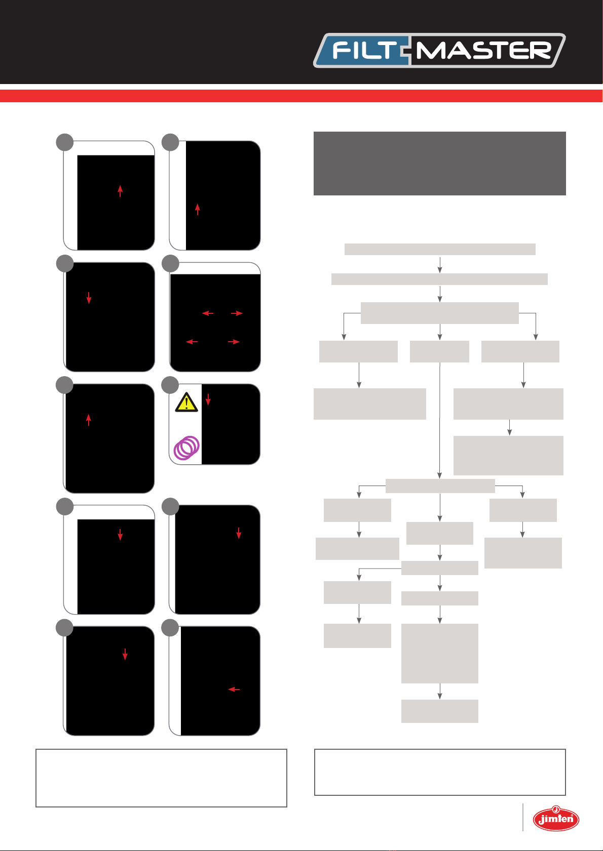
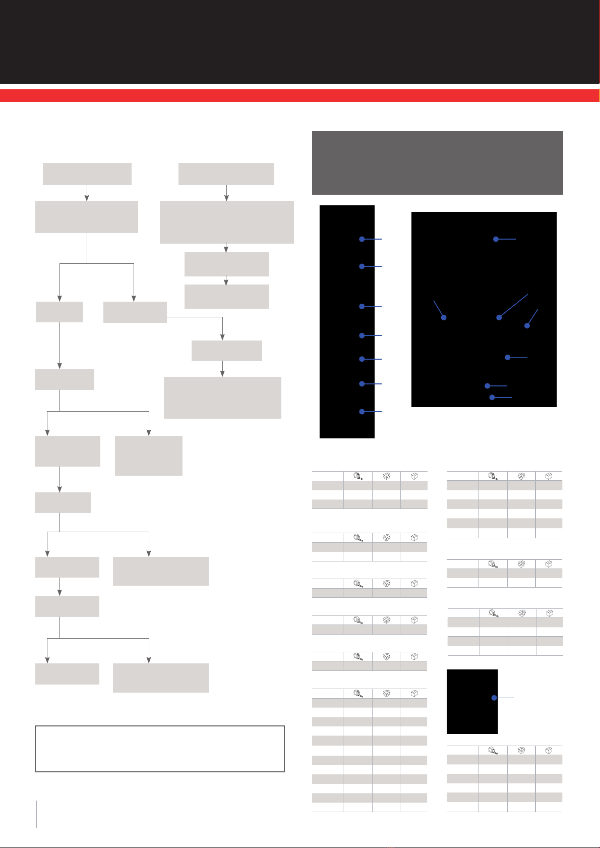
Steps for seasonal maintenance of discs.
Seasonal Maintenance
Cleaning the Discs
6
Operation and maintenance manual
34
12
To clean carbonates and iron deposits, put the discs in a
15 liter container that contains:
• 10 liters of water
• 2 liters of Hydrochloric Acid HCl 30%.
• Contact time: from 1 to 8 hours
• Agitate the discs several times with a stirring stick.
• Remove the discs carefully from the solution, put them
in the second large container with clean water and rinse
them very well before placing them back in the filter.
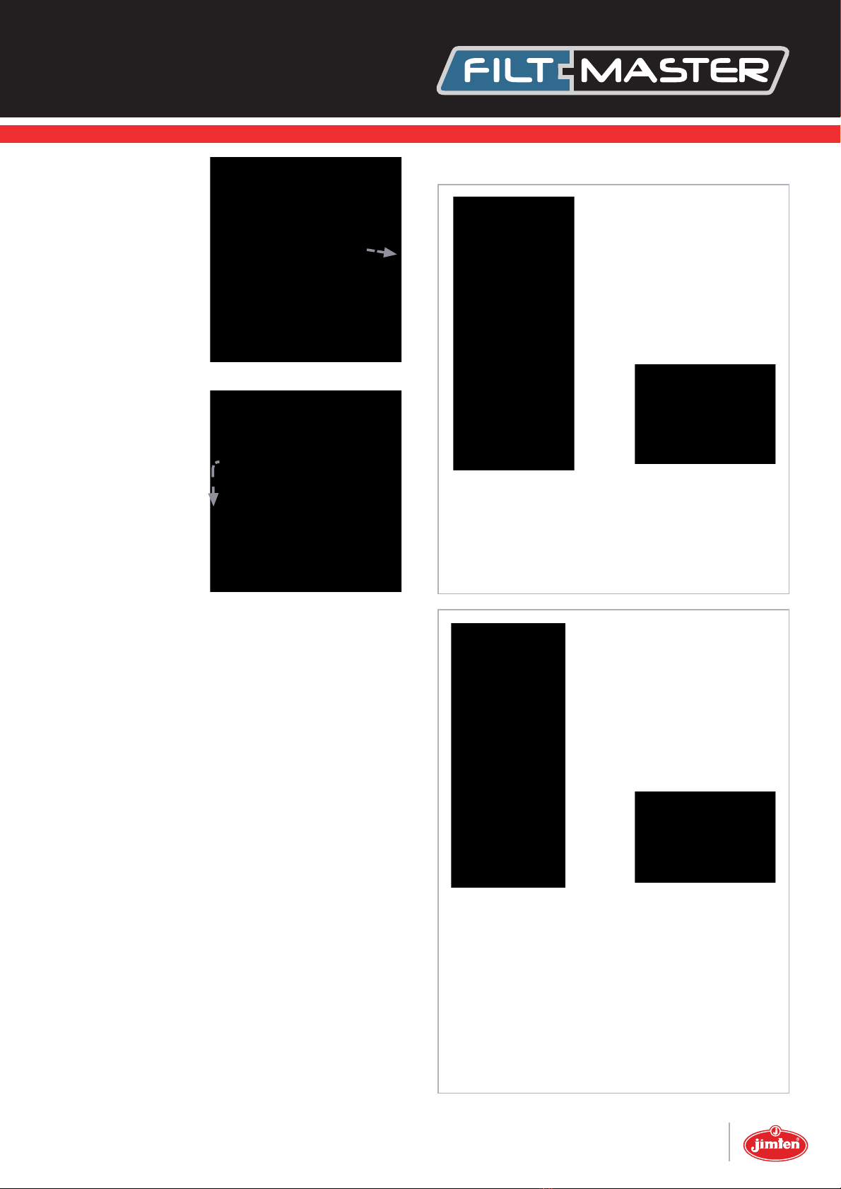
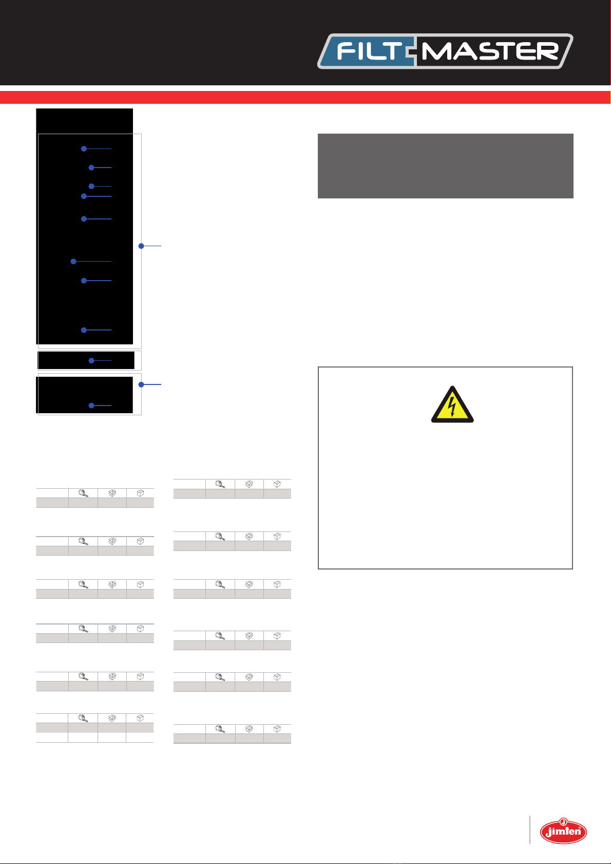
Make sure that the system is not under pressure! Release
the clamp (1) and remove the filter cover (2). Unscrew the
butterfly-nut on top of the filtration cartridge (3). Remove
the tightening cap (4). Remove the discs out of the car-
tridge spine (5).
• Personal protection equipment: safety glasses, gloves,
long pants, long sleeved shirt and shoes.
To clean organic and biological deposits, put the discs in
a 15 liter container that contains:
• 5 liters of water
• 5 liters of Sodium Hypochlorite NaOCl 10%.
• Contact time: up to 8 hours
• Agitate the discs several times with a stirring stick.
• Remove the discs carefully from the solution, put
them in the second large container with clean water
and rinse them very well before placing them back in
the filter.
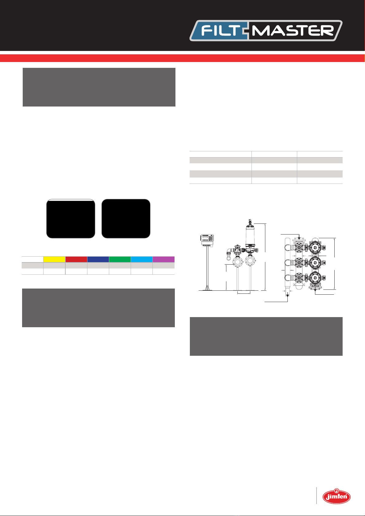
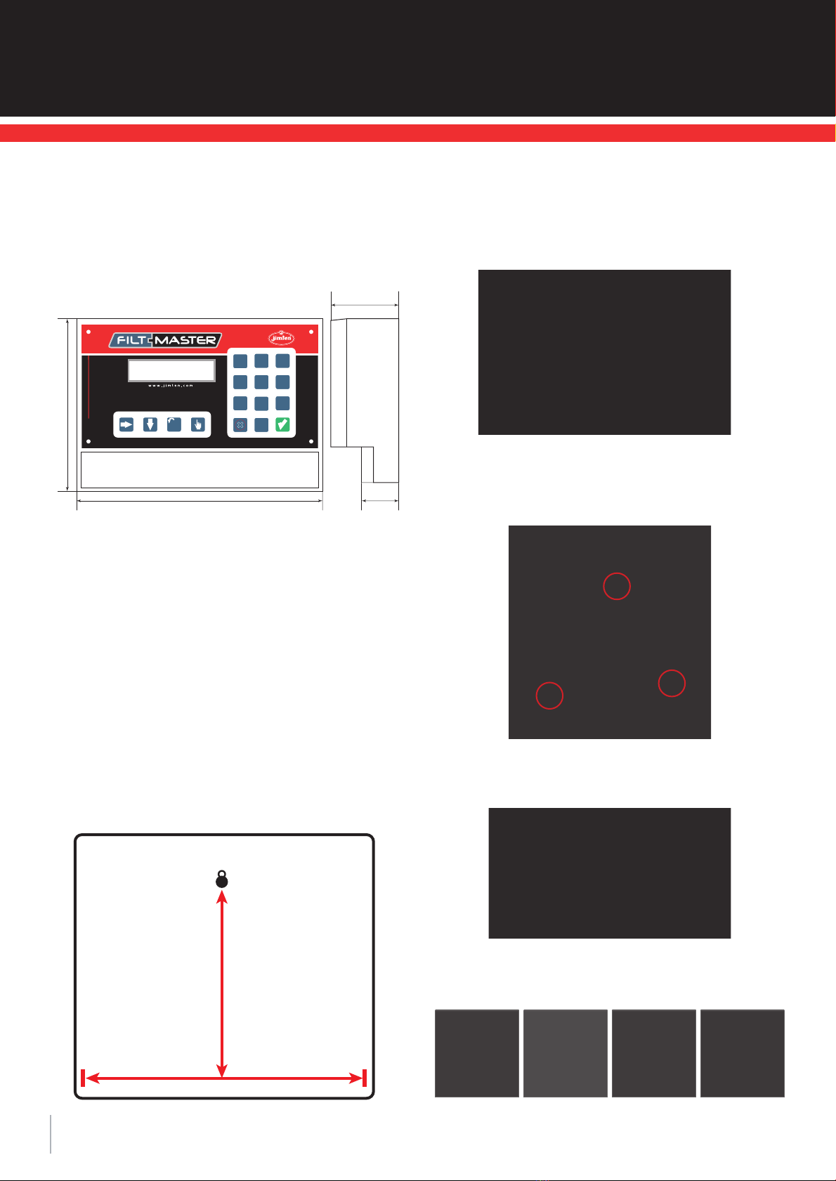
Clean regularly the hydraulic command filter
The ¾’’ filter installed in the inlet HDPE manifold provides
clean water to command hydraulically the backwash valves.
For regular maintenance, close the manual ball valve, get the
cartridge out and clean manually.
Winter time
To prevent damages in the filtration station by water
freezing in winter time, drain the system by leaving a drai-
nage valve open.

7
910
11 12
13 14
Troubleshooting
7
NO BACKWASH OPERATION
Check inlet and outlet pressure
Check & clean command filter
Check controller.
Manually operate the backwash cycle
Functioning
correctly
Functioning
correctly
Command not
received Receives
command
Command not
received
Check the inlet
manifold
Check the valves
Receives command
Remove the
valve’s cover
Check the
diaphragm and
the piston
Replace if needed
Check the 8mm
command micropipe Repair or replace
the hydraulic relay
if needed
Check & clean the
drain manifold
No command
transfer
Check electrical source.
Replace battery if
needed
Check electrical source.
Replace battery if
needed
Check solenoid electrical
connectors.
Repair or replace the
solenoid
Some commands
do not function
ATTENTION
Contact your local distributor.
ATTENTION
Carbonates react violently with hydrochloric acid
(foaming, gas).
56
78
Check the hydraulic relay
Place 20 micron discs
in the cartridge with the
striated side face down
20
micron

8
Continuous
backwash
Disconnect the control
micropipes from
the valves
Check inlet / outlet pressure
Check pressure differential gauge
and replace if needed
Check controller described above
Command
transfer
Check
controller
No command
transfer
Check the
solenoid
No command
transfer
Check the
hydraulic relay
No command
transfer
Command transfer
Replace the solenoid
if needed
Command transfer
Replace the hydraulic
relay if needed
Command
transfer
Replace control
panel
No command
transfer
Disconnect the
drain manifold
Locate the
nonfunctioning valve
Remove any obstruction
Repair the valve if needed
Nonstop backwash
cycle
Force backwash
manually
Contact your
local distributor
ATTENTION
Contact your local distributor.
Spare parts
and accessories
8
10
Operation and maintenance manual
1.- Filter cover
Code
97824 2” Std. 1 A-2
97345 2” 1 A-11
97346 3” / 2” L 1 A-4
1.- Transparent filter cover
(only for demonstration purpose)
Code
97347 2” 1 A-2
97348 3” / 2” L 1 A-4
2.- AISI 304 stainless steel clamp
Code
97350 2”- 3” 1 A-1
4.- Filter body o-ring
Code
97351 2”- 3” 10 A-10
5.- Filter body (3 ways)
Code
97770 2”- BBB 1 A-11
97772 2”- VBV 1 A-11
97771 2”- VVB 1 A-11
97773 2”- NNN 1 A-11
97775 2”- VNV 1 A-11
97774 2”- VVN 1 A-11
97777 3”- BBB 1 A-8
97779 3”- VBV 1 A-8
97778 3”- VVB 1 A-8
97780 3”- NNN 1 A-8
97782 3”- VNV 1 A-8
97781 3”- VVN 1 A-8
6.- Filter body (2 ways)
Code
97785 3”- BB 1 A-9
97784 3”- NN 1 A-9
97786 3”- VV 1 A-9
97788 4”- BB 1 A-8
97787 4”- NN 1 A-8
97789 4”- VV 1 A-9
7.- O-ring for cap
Code
97802 2” 1 4114
97803 3” 1 4114
10.- Discs kit (500 units)
Code
98813 20M 1 A-11
98495 25M 1 A-2
98814 50M 1 A-2
98815 100M 1 A-11
98816 130M 1 A-11
98817 200M 1 A-11
CONTINUOUS OR NON-STOP BACKWASHING
11
5
7
8
2
3
4
2
4
6
4
2
1
3.- PAFV clamp
(polyamide reinforced with fiberglass)
Code
97759 2”- 3” 1 A-2
8.- Female threaded cap
Code
51512 2” BSP 25 A-1
51535 3” BSP 15 A-2
51513 2” NPT 25 A-1
51536 3” NPT 15 A-2

9
VERY IMPORTANT
In this manual we deal with operations that in
some cases may mean physical risk for the opera-
tor who carries out these operations.
Precautionary, 220Vac controllers must be opera-
ted when switched off.
All the operations must be carried out using the
appropriate tools and safety protection means.
with the right safety protection.
Installation manual
9
The 8/16 output Filtmaster filter cleaning controller is
capable of activating sequentially up to 16 valves depen-
ding on the model.
In this manual, we will cover the installation of the con-
troller and the electrical wiring to all elements to be con-
trolled.
This manual has been prepared by JIMTEN for the exclu-
sive use of its customers. It is understood that the user is
responsible for use.
Where to install the controller.
To protect the Filtmaster filter cleaning controller from
damage, it must be installed in a dry place and away from
heat or electrical noise sources.
Never expose to continuous sunlight the controller screen.
For optimum vision, place the screen at the user’s eye
level, or keep viewpoint at 90 degrees angle.
13.- Deflector crown
Code
97336 2”-3” 1 A-10
14.- Automatic filter adaptor kit
Code
98782 - 1 4112
15.- Anti-return valve for automatic filter
Code
98781 - 1 4109
19.- Closing cover with joint
Code
97761 - 1 -
21.- Hydraulic piston washer
Code
97763 - 1 -
22.- Hydraulic piston cover
Code
97765 - 1 A-10
23.- Conical joint for hydraulic pistons
Code
97764 - 1 -
24.- Plastic screw for automatic
disc cartridge
Code
97766 - 1 -
25.- Disc support
Code
97767 - 1 A-8
26.- Spine without discs for automatic
filters
Code
98796 - 1 A-8
24
22
23
21
20
25
19
15
13
12b
26
14
Code
97335 2”-3” 10 A-10
12b.- O-ring for automatic disc
cartridge and manual before 2015
20.- Axis/spring wih hydraulic piston
Code
97762 - 1 -
97833 low pressure 1-

10
Together with the controller and inside the packaging
there are 6 packing glands for the cable input and 3 Rawl
plug and screw sets for correct wall mounting.
Use the mounting template (included) to mark the screw
location on the wall.
The Filtmaster filter cleaning controller has a transparent
protecting cover with a hinge:
Fixing to the wall is done by placing 3 screws according
to the following diagram:
To fix the lower screws, first remove the wiring cover:
The hinges and fasteners make the transparent protec-
ting cover mobile.
Screw location template.
How to install the controller.
The controller is designed to be installed directly on the
wall. These are the dimensions:
Operation and maintenance manual
190mm
120mm
60mm
250mm
145mm
198mm
F
1
7
0
9
54
23
6
8

11
Controller setup and power supply.
Remove the lower cover of the terminal block.
At the back, there are spare fuses and a wiring connec-
tion diagram for the controller.
Once the Filtmaster filter cleaning controller is situated
correctly we proceed to connect to power supply taking
into account polarity.
There are several options for power supply sources:
Power supply. General aspects:
The Filtmaster filter cleaning controller automatically de-
tects the power voltage, displaying a warning message if
that voltage is lower than that stipulated for each use.
The screen is displayed as it follows:
The terminal block is the same for all possible power
supplies. For this reason, we detail all possibilities:
In every case, we will make the connection with stripped
cable with a maximum section of 2 mm, while paying
special attention to using the appropriate screwdriver,
not leaving any loose filaments or too much stripped ca-
ble in sight.
It is highly recommended to mark the cables for future
maintenance or to track any breakdown.
We will use an appropriate packing gland for connecting
the cables into the plastic box. Maximum Ø of incoming
cables is 16 mm.
Pay attention to the right fixing on packing gland to gua-
rantee sealing of plastic box.
Once the controller is correctly mounted, we open the
front cover of the wiring terminal block.
Note: this terminal block will change depending on the
number of outputs and voltage of the controller model.
We connect here all electrical wires to external devices to
be controlled or from external devices providing informa-
tion to the controller.
Power supply area:
220 Vac power supply. The controller in-
corporates an internal transformer to
24Vac outputs (adaptable to an external
24Vac source).
24 Vac power supply. The controller gets
power from external 24Vac transformer.
12 Vdc power supply. The controller gets
power directly from a 12 Vdc battery that
can be charged through solar panel.
9 Vdc power supply. The controller gets
power from two 9 Vdc batteries that have
to be replaced depending on use.
Power
supply fuse
Outputs fuse
Outputs to backwash valves Inputs
ICT
COM AMP
Power supply fuse Outputs fuse
LOW VOLTAGE
1,6 Amp
1,6 Amp

12
This screen is displayed in the following cases:
In case of 220Vac, users are warned that the quality of
the power is lower than the 10% oscillation allowed by
electricity companies.
In case of battery supply, the message warns that the
current voltage is lower than recommended for the good
performance of the controller.
In these cases, while the warning message is displayed,
the controller is paused. If the voltage level is recovered,
the screen message will disappear and the controller will
continue the operation that was paused.
This function is particularly interesting in those cases
where latch solenoids are used, since it prevents valves
from being open.
If there is a MODEM available, the controller will com-
municate this fact.
Power supply 220 Vac Lower than 198 Vac
Power supply 12-9 Vdc Lower than 8.2 Vdc
220 Vac power supply:
We supply 220 Vac to the controller at the terminals mar-
ked on the diagram.
Electrical
fuse220
Vac.
Output fuse 24 Vac.
220 Vac.
220 Vac.
Internal transformer
It is of great importance that the connection to earth of
the controller is properly connected so that the incorpora-
ted (varistors, static filter and fuse) act when necessary.
The 220Vac controllers have an internal transformer that
generates the output voltage (24Vac).
There are two 24Vac outputs that can be used for:
• Checking if the system works correctly by testing if
there is 24Vac voltage in the these terminal blocks.
• In exceptional cases, conditioned by the power con-
sumption of solenoids connected to the Filtmaster fil-
ter cleaning controller or by the number of solenoids
connected to the same output, it is possible to install
an external transformer to get required power.
The controller can also be used for extracting the phase to
install an external switch for automatic-stop-manual ope-
ration of any external device (only for 220Vac models).
Precautionary, if we need to take the 220Vac from a three
phase power source, we recommend taking it from a di-
fferent device other than the following problematic ones
current, we will extract the220 Vac phase from a diffe-
rent one that acts on often problematic devices such as:
• Cold storage rooms.
• Frequency converters.
• Fertilizer pumps.
• Control panel contactors.
Other
devices
Earth
Operation and maintenance manual
24 Vac.
24 Vac.
1,6 Amp

13
As a general rule, the following precautions must be taken:
• Terminals of the battery must be tight.
• Terminals must be clean and protected against rust.
• In case of solar panels, they must be clean, orientated
and well maintained.
This controller model has only one output with polarity
(pay attention to the connection), although all the pro-
tection elements and fuses meet the same quality stan-
dards.
The same power cable must be used for supplying power
to the outputs of controller. (In some cases, it is possible
to install two batteries).
12 Vdc power supply (batteries)
In battery-supplied controllers, pay special attention to
the quality of the connections made.
If an alternative manual control is installed, it is neces-
sary to take the precaution of having a second protection
fuse for the manual control of the system.
Originally, the output fuse is a 1,6 Amp fuse. This value
must never be exceeded under any circumstances.
Furthermore, the output supply has a 39V protection
varistor.
Output
Auto
Marker
Manual
Selector
NOTE
Once a varistor has acted, it no longer fulfills its
performance specifications and must be replaced.
12 Vdc (positive)
12 Vdc (negative)
NEGATIVE
POSITIVE
We recommend using only 2Amp fuses.
Never use fuses higher than 2Amp. In case it is fused
repeatedly, you should contact JIMTEN’s technical ser-
vices.
The power supply is protected by a fuse, varistors and a
network filter.
These varistors have the property of short circuiting when
the voltage is higher 220Vac, causing the fuse to blow.
They are placed between phases and phase to earth. If
we detect that the fuse is fused, this can be a result of
varistors operating. Therefore, we must check and repla-
ce them if necessary.
Moreover, this connection can also be used for extracting
the appropriate phase for the installation of a network
representation or of an alternative manual control, as
shown in this diagram.
The 1,6 Amp output fuse of the controller only acts on
the output common.
Never use the common phase as an output common sin-
ce, in this case, the protections that the controller in-
corporates (varistors, RC circuits and fuse) are disabled.

14
We recommend to connect the phase to earth to the
controller.
Optionally, a solar panel with its regulator can be insta-
lled to keep the battery charged with endless autonomy.
The solar panel charge requirements or the autonomy of
battery will be more defined by the power consumption
of solenoids and working hours per day of these solenoids
than the power consumption of controller itself.
The main characteristic of this latch solenoid is that it
consumes only during opening and closing operations.
Therefore, it does not consume power while the valves
are actuated (for practical purposes, there is no differen-
ce between operating for 1 hour or 20 hours).
The SLEEP function is a distinguishing feature of this
model. The controller becomes disconnected in order to
save energy. It is automatically activated for miliseconds
every minute to check if it has to do any operation.
As the 12 Vdc model, it does not have light screen and
turns into SLEEP mode for energy-saving reasons.
The 9 Vdc controller has quick connectors for the power
supply batteries and also for the 9 Vdc outputs.
Number of batteries is doubled to guarantee 3 months of
autonomy in normal working conditions.
This model is produced with standard 9 Vdc battery quick
connectors, but can also work with 12 Vdc batteries in
order to extend its autonomy.
The battery recommended by JIMTEN for this function
has a 550mAh charge.
The autonomy of a battery greatly depends on temperatu-
re and humidity conditions.
In case of automotive batteries, we recommend maintai-
ning the acid level.
During inactive periods, we recommend taking out the
battery and keeping it under ideal conditions
If the battery is recharged by solar panels, they must
be suitably maintained, by keeping them clean and well
oriented to assure that the battery is fully charged.
NOTE
12 Vdc controllers, for obvious energy-saving re-
asons, do not have light screen.
NOTE
We recommend using longlife well known brand
Ni-Cad batteries.
NOTE
Never program pauses lower than 4 seconds bet-
ween latch solenoid activation times since the
electronic condenser requires that minimum
time to accumulate the necessary power for acti-
vation/deactivation.
9 Vdc power supply (batteries)
There is a model of Filtmaster filter cleaning controller
that works with 9 Vdc batteries.
Unlike the previous controller models, it can only work
with two-wire latch solenoids (with invertible polarity).
Wiring:
+9 Vdc
electronic
(RED)
(WITHOUT
CONNECTION)
-9 Vdc
electronic
(BLACK)
+9 Vdc
outputs
(RED)
-9 Vdc
outputs
(BLACK)
Operation and maintenance manual
Electronic power
supply and
program saving Output power
supply to 9 Vdc
electrorelais

15
Most solenoids work from 9 to 12 Vdc, but there are
some cases when solenoids must be powered with a hig-
her voltage. In these cases, we can do as follows:
Once this operation is carried out, the screen shows the
controller status.
Another characteristic of this controller is that it discon-
nects its screen in order to save energy. If we want to
program it again, we must press any key for a few se-
conds until it activates again.
To turn it off again, we will key in at the ‘’STATUS
SCREEN’’:
When validating, the screen will turn off, but the contro-
ller will be fully operational.
NOTE
The specific operation of this kind of controller
and the fact that the low power consumption of
all its functions is a priority, make inadvisable ins-
tallations that require an active input since this
means multiplying the power consumption and
therefore reducing its autonomy.
NOTE
Due to the fact that the highest power consump-
tion occurs when the screen is on, after learning
how to operate the controller during the first
programming, we recommend to swap the two
batteries so that the battery in best condition is
available for the electronics.
9 Vdc
Sleep controller? will be shown
9 Vdc 9 Vdc 18 Vdc+=
VERY IMPORTANT
Battery controllers switch the screen off to save
power consumption when no key has been touched
for a minute.
To switch on the screen again… Keep a key pres-
sed for a few seconds.
Electric connection to backwash valves
The connection to backwash valves is done through so-
lenoids. Current intensity must not exceed 1,6 Amp for
the total of solenoids connected simultaneously to the
output ports.
We must bear in mind that the internal transformer gives
a maximum intensity of 40VA, so we will take into con-
sideration the maximum power consumption, depending
on the number of solenoids and relays working simulta-
neously in the worst case scenario.
The Filtmaster filter cleaning controller can be connec-
ted either to continuous consumption solenoids or to
latch solenoids.
The connection is the same for 12 Vdc controllers, ta-
king into account the power supply polarity and the po-
larity of solenoids.

16
Output connection terminal block
Invertible polarity latch solenoids vary their performance,
interchanging the order of the cables (consult manufac-
turer). That is to say, they change from normally open
(N.O.) to normally closed (N.C.).
Some manufacturers make specific solenoids for each
operation.
The Filtmaster filter cleaning controller, can work with
different brands of latch solenoids.
JIMTEN recommends a solenoid that, for connections
to normally-open valves, the common is the black cable
while the green cable is the common for connections to
normally-closed valves.
For these solenoids the output common must be the
black cable (check for other models), while for 24Vac and
12 Vdc solenoids the connection polarity is not impor-
tant, although it is recommended to use the same colour
for the output common in order to make future mainte-
nance work easier.
Nous pouvons apprécier qu’il existe une différence de nom-
bre de sorties s’il s’agit d’un programmateur latch.
In this case the internal relay no.1 is responsible for in-
verting the polarity of latch solenoids.
We will connect the solenoids of the backwash valves
according to the following diagram:
There are 4 common terminals (internally bridged).
If there are many cables to be connected to these ter-
minals, we will install an external terminal block for an
appropiate connection to the controller.
If power consumption is higher than 4Amp per output,
resulting from solenoids with greater power consumption
or from the simultaneous connection of a number of so-
lenoids, an external relay should be installed.
As a precautionary measure, mainly for controllers that
make many operations daily, this relay should be insta-
lled to increase the working lifetime.
Power fuse
OUTPUTS TO THE VALVES ENTRÉES
Output fuse
Output fuse
Output fuse
Operation and maintenance manual
1,6 Amp
1,6 Amp
1,6 Amp

17
Furthermore, the installation of an external relay is good
because this increases the galvanic separation between
the solenoid and the controller. Another advantage is that
the relay can bequickly changed in case of breakdown.
The devices shown on the previous table are those in the
following diagram:
In the previous diagram, we see the connections to the
water meter and the differential pressure gauge. These
inputs are fixed for these devices.
Electric connection to pumps
In addition to the controller, backwash valves and fil-
ters, there are other devices (pumps, mixers, fertilizer
pumps, etc.).
These elements are based on electric motors, and so
their installation and control follow common guidelines.
Communication connections
The controller can communicate with different devices:
There are 3 connector types located immediately above
the connection terminal block of the digital inputs.
There are 4 warning lights that inform us whether the
controller is sending or receiving information (from mo-
dem or ICT), useful information for setup and assistance
operations.
Input connection terminal block
The controller has 7 contact voltage-free inputs, that is
to say, the controller recognises them when there is a
short circuit between the common input and the corres-
ponding input.
The function of these inputs is the following:
The previous diagram is valid both for the automation
of pump motors, mixers and electric fertilizer injection
pumps.
Symbol Function
P MECHANICAL DIFFERENTIAL PRESSURE SWITCH
F NETWORK WATER SENSOR/ACTIVE PUMPING
WM / CA WATER METER
E4 -----without use-----
E5 -----without use-----
E6 -----without use-----
E7 -----without use-----
INPUTS
INPUTS
1,6 Amp

18
ICT connection (via radio)
Through a radio connectivity module, this Filtmaster fil-
ter cleaning controller model can command an ICT trans-
mitter that will open/close valves at long distances (see
ICT specifications).
In this case, this module can control 96 more valves by
simply connecting both devices.
This module includes the necessary cable.
The modem connection is easily done by using the appro-
priate cable supplied by JIMTEN.
In the male socket plug that must be connected to the
MODEM there are two works to be done.
RS232 connection
By using this connector, the controller can communicate
with a PC through modem or by cable for programming or
downloading data.
There are a large number of modems in the market. JI-
MTEN has officially approved different GSM modem mo-
dels for the Filtmaster filter cleaning controller.
If you have a different modem model, please contact
JIMTEN’s technical department to verify its compatibility.
Modem connection:
Wiring
Jumpers
PIN 2 MODEM CONNECTOR PIN 1 CONTROLLER
PIN 6 MODEM CONNECTOR PIN 2 CONTROLLER
PIN 9 MODEM CONNECTOR PIN 3 CONTROLLER
PIN 7 WITH 8
PIN 11 WITH 12
NOTE
For the correct performance of the MODEM, the
PIN number request must be deactivated.
NOTE
The connection between both devices must be as
close as possible and the cable connecting them
must be outside the area of influence of any devi-
ce that may generate interference (power cables,
motors, etc.).
CONNECTIONS JUMPERS
INPUTS
INPUTS
Operation and maintenance manual

19
Setup
Special screens
The controller has some special advanced configuration
screens for adjusting the controller to the installation on
exceptional occasions.
One of these screens allows the installer to check that
the connections are correctly made and, at the same
time, to test the devices connected to the Filtmaster fil-
ter cleaning controller.
Testing the outputs
By pressing , the controller version is shown in the
screen status.
back to the controller main screen.
With this combination, we have quickly activated pro-
gram number 20 with a 5 second operation time for all
16 outputs.
Now, the only thing to be done is to activate manually
program number 20 so the outputs operate sequentially.
Technical characteristics
Testing the inputs
In the status screen, pressing
F
we will access the re-
ports provided by the Filtmaster filter cleaning controller.
The following will appear immediately:
They are voltage-freee inputs and they can only be de-
tected when the specific input is connected to the input
common through the controller.
This model requires the RADIO CONNECTIVITY MODULE.
The compatibility between the Filtmaster filter cleaning
controller and the ICT transmitter is guaranteed by the
ICT Transmitter version 6.
NOTE
Never make any connection between controllers
while ON.
Never do testing without connecting the aerial to
the transmitter.
VERY IMPORTANT
Before doing this operation, the person who is
going to carry out the activation must be aware
that this operation will activate outputs connec-
ted to pumps or fertilizer pumps that can dama-
ge seriously the network.
That is why we recommend that these test opera-
tions always are done after opening a valve and,
if possible, disconnecting the three-phase star-
tup of the motors startup.
Precautionary, we recommend deleting this pro-
gram before definitively programming the filter
cleaning controller.
---- ----
Dimensions 250 x 190 x 120 mm
Pin 6 conector modem PIN 2 CONTROLLER
Weight 2 Kg
Material ABS
Dust/water protection IP-56
INPUTS

20
Pr =0.0 atm pfc 08:32
NEXT V=0000 T=00:00 ti
Voltage (10%)
220 Vac
12 Vdc
9 Vdc
Power consumption 220 Vac / 12 Vdc/ 9 Vdc 75mA / 15mA / 400μA.
Power consumption per output 20 mA.
Power consumption per input 8 mA.
Internal battery NI-CAD 3.6V 110mA/H
Duration of battery off 1 year
Working temperature 0ºC to 60ºC
Working humidity 0 to 95% non condensing
Power fuse 2 Amp
Outputs RELAY
Output fuse 1,6 Amp
Output isolation 8 Amp 4mm
Inputs Optocouplers
Input isolation Optical
Overvoltage protection Varistors
Problem Action to be taken
The screen is off
- Check connection to power
- Check power is on
- Check fuses
A valve does not work - Check that valve is active
- Measure the output voltage
No valve works - Check output fuse
- Check possible short circuitin cables
Loses data - Check the battery
- Change battery
Filters CONTROLLER MODEL
(program version)
PPRESSURE GAUGE ACTIVATED
Displayed when there is a need for cleaning through
this device.
CWATER METER DETECTED
Displayed when it detects a meter pulse (if this device
exists).
F
CLEANING PERMISSION ACTIVATED
Displayed when it detects water in the network
(through minimum pressure swith, flow sensor, auxiliar
water pump or another controller). If water is detec-
ted, then cleaning is allowed.
Troubleshooting
Next, we offer users the best steps to follow when facing
an anomaly in the performance of our controller:
Components
Digital display
The display allows us to program the cleaning process, to
set up the system adapting it to the needs of the installa-
tion and to check all its operating parameters.
On the “STATUS SCREEN”, the controller shows in real
time what is happening in the filtration station.
This information will be very important to set up the con-
troller, trying to achieve a balance between the correct
cleaning of the filters, water saving and the power con-
sumption saving (extremely important in battery operated
facilities).
The display has 2 lines with 20 characters each one.
Top line
Information regarding the model, status of the inputs and
current time.
If the problem is not solved, please contact your local
dealer or our aftersales department.
Users
manual
10
The Filtmaster filter cleaning controller is an easily pro-
grammable powerful device designed to process automa-
tically all the functions of a modern filtration station.
This version is able to control the automatic cleaning of 8
to 16 filters, depending on the model.
The high number of parameters that can be controlled by
the Filtmaster filter clenaing makes it adaptable to any
filtration system: from the most complex to the simplest.
The programming by the user (data input) through the
display allows an easy communication that makes the
use of this controller really simple and easy to unders-
tand by users.
Operation and maintenance manual
Table of contents
Popular Water Filtration System manuals by other brands

WaterChef
WaterChef Countertop C7000 Installation, use & care guide

Eureka Forbes
Eureka Forbes Aquaguard GLORY user manual

Saunatec
Saunatec Saunatec Water Filtration System ASX100 Installation & operation manual

UV Pure Technologies
UV Pure Technologies Hallett 1000 maintenance

Contracor
Contracor CK-50 user manual

Grunbeck
Grunbeck pureliQ:R Operation manual