2
PL Instrukcje obsługi
(Tłumaczenie oryginalnej instrukcji)
UWAGA!
PRZED ROZPOCZĘCIEM EKSPLOATACJI DŹWIGNIKA
NALEŻY DOKŁADNIE ZAPOZNAĆ SIĘ Z NINIEJSZĄ
DOKUMENTACJĄ TECHNICZNO–RUCHOWĄ W CELU
POZNANIA BUDOWY, DZIAŁANIA MECHANIZMÓW,
OBSŁUGI I ZASAD BEZPIECZEŃSTWA PRACY W
CZASIE UŻYTKOWANIA DŹWIGNIKA.
PRZEZNACZENIE
Dźwignik jest przeznaczony do częściowego podnosze-
nia pojazdów w celu dokonania napraw lub zabiegów
konserwacyjnych.
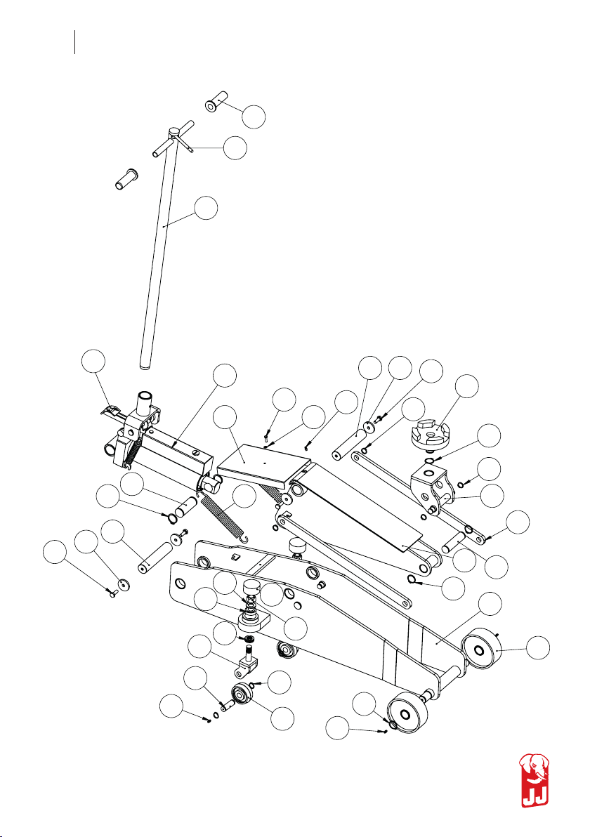
OPIS BUDOWY
Dźwignik składa się z trzech zasadniczych zespołów
funkcjonalnych: rama – wózek; pompa; ramię nośne.
Układ podnoszący
W skład układu podnoszącego wchodzi - dźwignia ręcz-
na (29), dźwignia nożna – pedał (32) z których napęd
przenoszony jest na pompę (23). Pompa połą-czona
jest z ramieniem podnoszącym (5), na którym umoco-
wane jest siodełko podporo-we (21).
Układ opuszczania
W skład układu opuszczania wchodzi zawór spustowy
połączony poprzez dźwignię z tarczą przesuwną. Prze-
suw tarczy następuje za pomocą końcówki mimośrodo-
wej dźwigni ręcznej połączonej z rączką (R).
INSTRUKCJA OBSŁUGI
• Zabezpiecz podnoszony pojazd przed przesunięciem.
• Siodełko podnoszące można unosić szybciej używa-
jąc pedału nożnego.
• Ustaw siodełko w prawidłowej pozycji w miejscu do
tego przeznaczonym, aby nie uszkodzić części pojaz-
du podnoszonego.
• Poprzez poruszanie dźwigni (dyszla) na dół i do góry
siodełko dźwignika będzie podnosić pojazd.
• Zabezpiecz podniesiony pojazd stałą podporą przed
opadnięciem.
• Przed opuszczeniem pojazdu usuń stałą podporę.
• Poprzez obrót ręcznej dźwigni w prawo siodełko
dźwignika będzie opadać.
UWAGA!
• Dźwignik musi być ustawiony na twardym podłożu,
aby mógł bez przeszkód wjeżdżać pod podnoszony
pojazd.
• Zabrania się pracy przy lub pod podniesionym po-
jazdem bez zabezpieczenia pojazdu stałą podporą
przed opadnięciem.
• Zabrania się zwiększania nominalnej wysokości
podnoszenia.
• Zabrania się przeciążania dźwignika.
• Zabrania się przesuwania dźwignika pod obciążeniem.
KONSERWACJA
Sprawdzaj raz w roku poziom oleju (zbiornik powinien
być pełny).
Smaruj ruchome, współpracujące części, szczególnie
tuleję pedału (32) i łożyska kółek skrętnych i dużych
przy pomocy smarowniczek.
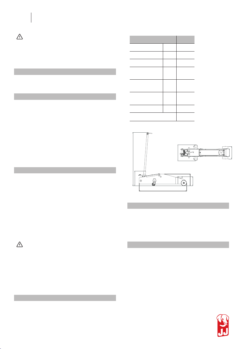
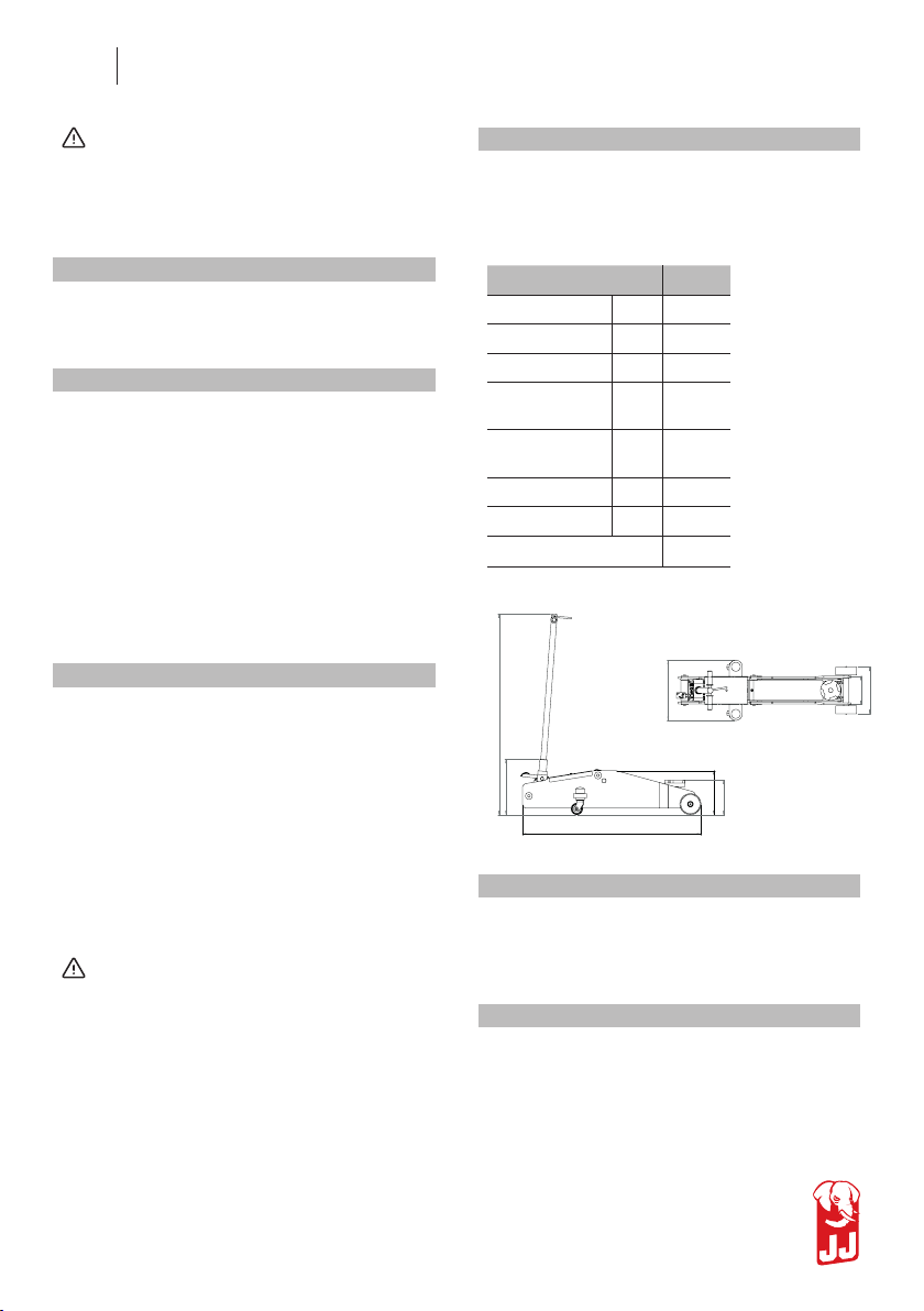
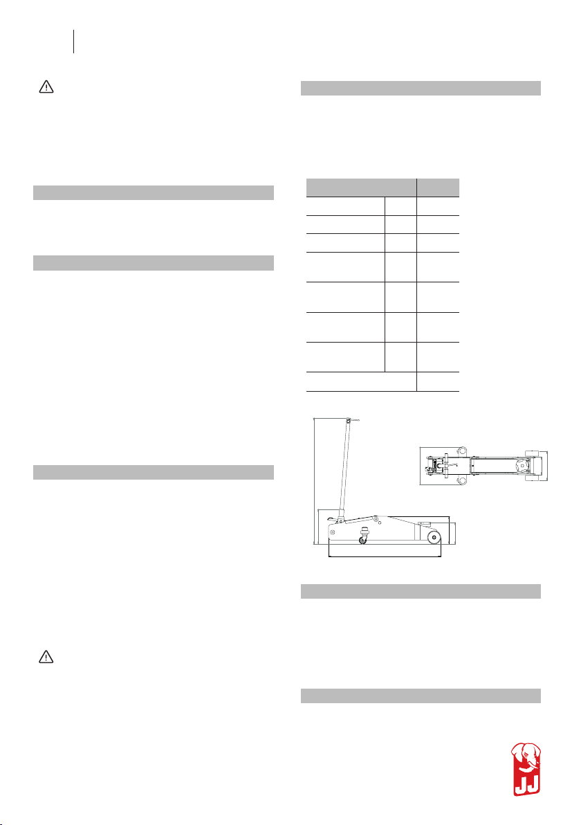
DANE TECHNICZNE 10/920
Maks. udźwig kN 100
Długość mm 1238
Szerokość mm 417
Min. wys.
siodełka mm 239
Maks. wys.
siodełka mm 920
Wysokość
dyszla mm 1007
Masa
podnośnika kg 132
Rodzaj oleju HV32
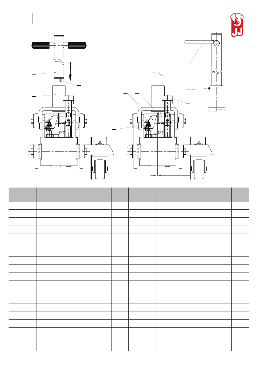
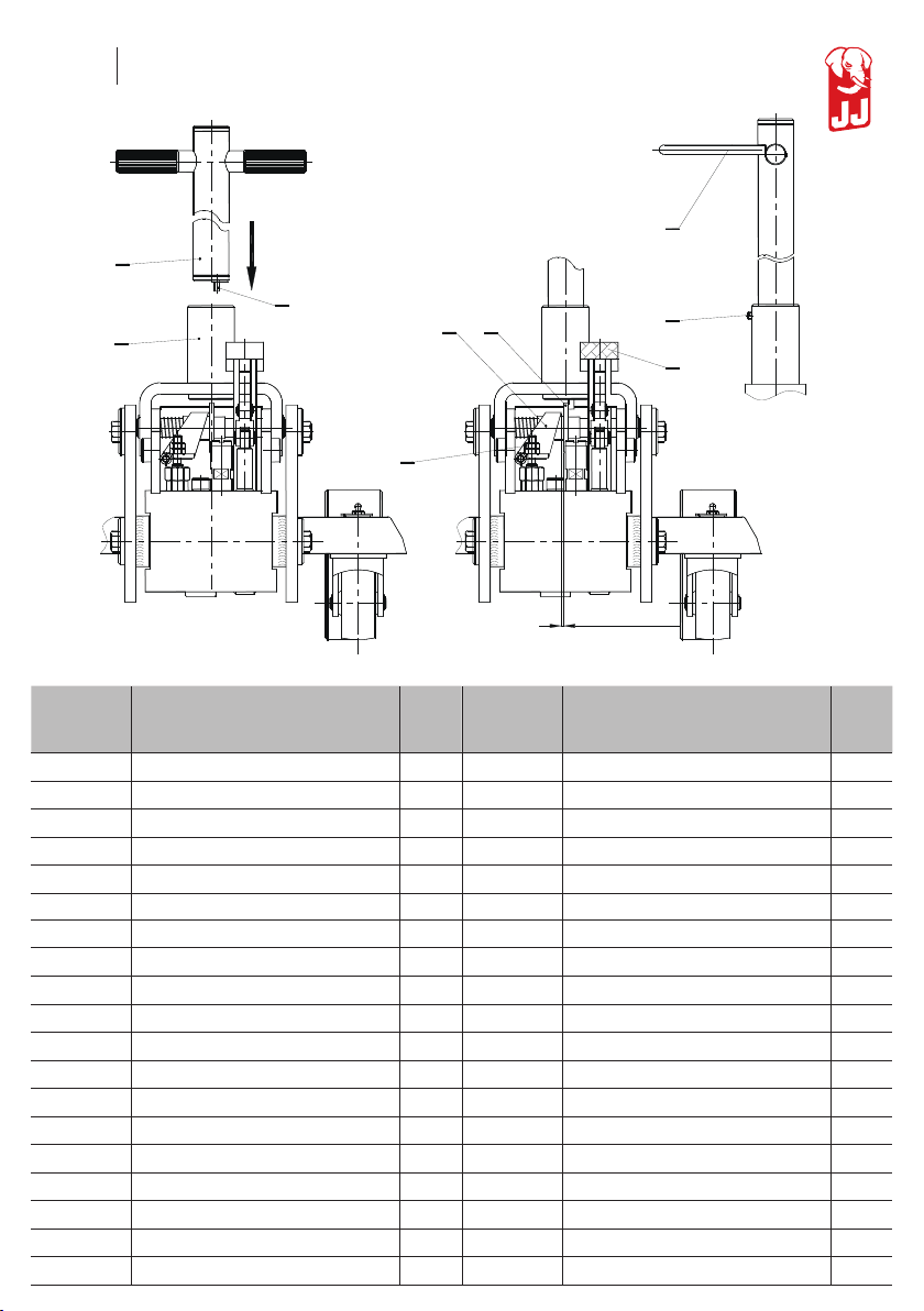
INSTRUKCJA MONTAŻU DYSZLA
Odsunąć tarczę (33) i odchylić dźwignię (34) w lewo
około 10 mm. Wprowadzić dźwignię ręczną (29) w jarz-
mo jednocześnie ustawiając go w taki sposób, aby trz-
pień (38) znalazł się po prawej stronie tarczy (33) – jak
widać na rysunku. Następnie wkręcić do oporu wkręt
dociskowy (35).
REGULACJA ZAWORU OPUSZCZANIA
Poluzować nakrętki (36); dolną nakrętkę ustawić tak aby
luz pomiędzy tarczą (33) a dźwignią (34) wynosił 1 do 2
mm, skontrować górną nakrętką.
305
384
1238
239
324
197
417