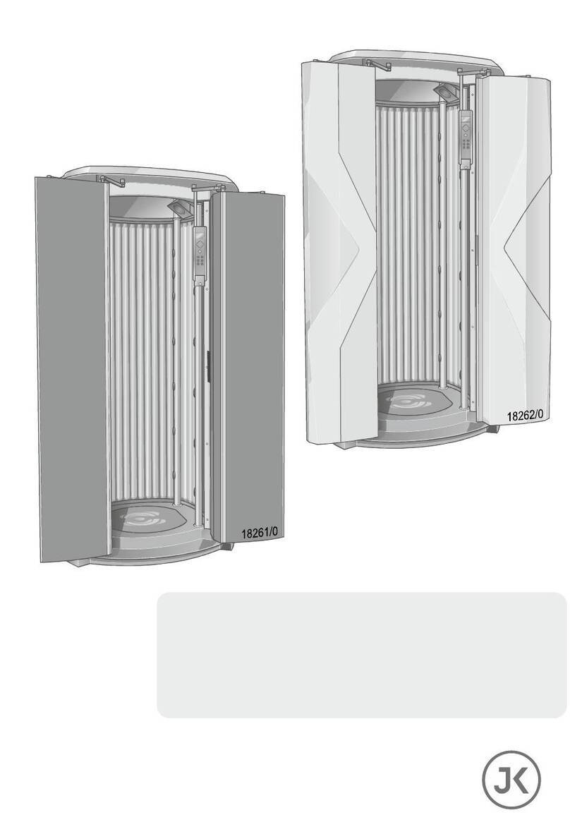
JK 127/48-4 TT User manual

Installation Instructions
1013661-01 / us / 04.2015
Model-No.: JK 127 / 48-4 (TT)
Model-No.: JK 127 / 52-4 (TT)
Model-No.: JK 127 / SA 52-4 (TT)

Contact information
2/70
Contact information
Manufacturer
JK-Products GmbH
Köhlerhohner Straße
53578 Windhagen
GERMANY
Tel.: +49 (0) 22 24 / 818-140
Fax: +49 (0) 22 24 / 818-166
Technical Service JK Products & Services, Inc.
#1 Walter Kratz Drive
Jonesboro, AR 72401
800-445-0624 (toll-free)
870-935-9046
e-mail: support@jkamerica.com
http://support.jkamerica.com
WARNING!
Read these installation instructions.
Failure to observe these instructions:
• may result in serious injury and death,
• can result in damage to the device and the
environment.
–For the safety of yourself and others, read and observe
all instructions contained herein before operating the
device.
–Please make the instructions and additional information
available to anyone who operates or services the de-
vice.

Contact information
04/2015 1013661-01 Installation instructions– 3/70
NOTE:
The illustrations and text apply to the Model-No.: JK 127/.., even
if only one unit is shown.
NOTE:
The right to make technical modifications concerning the
specifications and information in these operating instructionsl is
reserved.
Reprinting and reproduction, in whole or in part, of this manual is
only permitted with our previous written approval and with
specification of the source.
Copyright
The copyright remains with JK-Holding GmbH.
The contents may not be duplicated (in whole or part), distributed or utilized
for competition purposes without authorization or disclosed to other parties.
The right to make technical changes in regard to the figures and information
contained in this instruction manual is reserved!

Table of contents
4/70
Table of contents
2What certain words and signs mean (Glossary) ........................6
2.1 Definitions........................................................................................6
2.2 Warning signs..................................................................................6
2.3 Symbols on the device ....................................................................8
2.4 Instructions pertaining to
a risk of fire, electric shock, or injury to persons............................10
2.5 Instructions pertaining to a risk of damage to the machine ...........11
3Information for authorized, trained and qualified staff ............12
3.1 Transport and transport damage...................................................12
3.2 Ventilation......................................................................................13
3.3 Installation location........................................................................13
3.4 Electrical connection .....................................................................15
3.5 Power OFF device and
secure against being switched on again.......................................16
3.6 Maintenance..................................................................................17
4Information for dismantling and assembly ...............................18
4.1 Tools and equipment.....................................................................18
4.2 Scope of delivery...........................................................................18
4.2.1 Optional.........................................................................................18
5Dismantling..................................................................................19
5.1 Removing the transport locks........................................................19
5.2 Dismantling the acrylic panel and side panel ...............................19
5.3 Removing the front panel ..............................................................21
5.4 Dismantling the tray.......................................................................23
5.5 Dismantling the AQUA / AROMA SYSTEM..................................24
5.6 Model-No. JK 127/48-4 TT / JK 127/52-4 TT:
Dismantling the circuit board (DALI controller) ..............................25
5.7 Dismantling the control unit ...........................................................26
5.8 Dismantling the component rack ...................................................26
5.9 Dismantling the air conditioning.....................................................28
5.10 Dismantling the canopy .................................................................29
5.11 Removing head end and foot end, rear panel ..............................33
6Assembly .....................................................................................35
6.1 Setting up the rear panel ...............................................................35
6.2 Mains connection and connection of timers .................................36
6.3 Refitting head end and foot end ....................................................38

Table of contents
04/2015 1013661-01 Installation instructions– 5/70
6.4 Installing the canopy .....................................................................39
6.5 Optional: Mounting an enclosed tanning tunnel ...........................42
6.6 Mounting the shoulder tanner / connecting the audio system ......43
6.7 Refitting the air conditioning..........................................................43
6.8 Mounting the component rack.......................................................44
6.9 Mounting the control unit...............................................................46
6.10 Model-No. JK 127/48-4 TT / JK 127/52-4 TT:
Mounting the circuit board (DALI controller).................................. 47
6.11 Mounting the AQUA / AROMA SYSTEM ......................................47
6.12 Refitting the tray............................................................................49
6.13 Refitting the front panel .................................................................51
6.13.1 Check for correct positioning of the acrylic panel.........................54
6.14 Installing sensor and base station.................................................55
6.15 Acceptance testing........................................................................56
7Technical data .............................................................................57
7.1 Power rating, electrical specifications and noise level ..................57
7.2 Dimensions ...................................................................................57
7.3 Lamp configuration........................................................................57
7.4 Company nameplates/Warnings ................................................... 57
8Appendix......................................................................................58
8.1 Model-No.: JK 127/ ...: EMC information...................................... 58
8.1.1 Table 201: Guidelines and manufacturer's declaration –
Electromagnetic emissions ...........................................................58
8.1.2 Table 202: Guidelines and manufacturer's declaration –
Electromagnetic interference ........................................................59
8.1.3 Table 204: Guidelines and manufacturer's declaration –
Electromagnetic interference ........................................................60
8.1.4 Table 206: Recommended safe distances between
portable and mobile HF communications equipment and
Model-No.: JK 127/ ... ...................................................................61
9JK-Products, Inc. – Limited Warranty ....................................... 62
9.1 Limited Acrylic Warranty ...............................................................63
9.2 Warranty Claims............................................................................63
9.2.1 Policy & Procedures......................................................................63
9.2.2 Labor Warranty Claim/Credit Procedures .....................................64
9.3 Limited Lifetime Warranty .............................................................65
10 Index.............................................................................................68

What certain words and signs mean (Glossary)
6/70
2What certain words and signs mean (Glossary)
2.1 Definitions
Authorized, trained and qualified staff
Qualified staff from an external company who have been trained and author-
ized by the manufacturer for assembly and maintenance work with specific
devices.
2.2 Warning signs
Danger notices, nonobservance will lead to death or serious injury:
DANGER!
Type and source of danger, e.g. 'DANGER – High volt-
age!'
Description of the consequences, e.g. 'You can be killed or
injured by an electric shock!'
Countermeasures:
–Disconnect device from power supply before opening.
–Do not reach into the inside with the device switched
on.
Warning notices, nonobservance can lead to death or serious injury.
WARNING!
Type and source of danger, e.g. 'WARNING – Risk of
injury!'
Description of the consequences, e.g. 'You can burn your
hand (skin, face)!'
Countermeasures:
–Do not touch hot parts and nearby surfaces.
–Wait until hot parts and surfaces have cooled down.
WARNING!
Crushing hazard, e.g. when closing the bed base!
Fingers can be jammed.
–Do not hold fingers between bed base and front panel.

What certain words and signs mean (Glossary)
04/2015 1013661-01 Installation instructions– 7/70
Caution notices, nonobservance can lead to less than serious injury or
damage of property.
CAUTION!
Heavy parts! Risk of injury!
The word 'Caution' together with the warning sign points out
that less than serious injury can be expected here.
Countermeasures:
–Avoid doing this.
–Do that.
NOTICE
Damage to the device possible!
The word 'NOTICE' without warning sign points out that danger for devices,
materials and the environment can be expected here.
Countermeasures:
–Avoid doing this.
–Do that.
Important information:
NOTE:
This symbol does not identify safety notices, but states infor-
mation for a better understanding of the processes.

What certain words and signs mean (Glossary)
8/70
2.3 Symbols on the device
The following symbols are displayed on the device:
Manufacturer, production year and month
Type BF applied part1
Follow Operating Instructions.
Therefore you must never fill the AQUA SYSTEM canister
with tap water or other liquids.
Do not add any liquid that remains in the old canister to
the new AQUA SYSTEM canister!
Note the expiration date on the AQUA SYSTEM canister.
Where there are great differences in temperature between the transport
route and the installation site the device may not be put into operation im-
mediately after being set up.
Wait at least 2 hours before connecting the device to the power supply.
Maximum transport weight
Do not stack!
This side up.
Keep dry.
1Devices with physical contact between device and user belong to category
BF (body float).

What certain words and signs mean (Glossary)
04/2015 1013661-01 Installation instructions– 9/70
Temperature limitations.
The temperature limits are noted next to the upper and lower horizontal line.
Recyclable material.
Polystyrene
Cardboard
Mixed paper
Steel
Wood

What certain words and signs mean (Glossary)
10/70
2.4 Instructions pertaining to a risk of fire,
electric shock, or injury to persons
WARNING – when installing this sunbed, basic precautions should always be
followed, including the following:
Read and follow all instructions.
DANGER!
You can be killed or injured by an electric shock!
Electricity throughout entire device!
Assembly and electrical connection must comply with
national and local regulations.
–The unit may only be assembled, installed, upgraded or
repaired by specially qualified personnel who have
been trained by JK Global Service Division or an au-
thorized partner.
–Install this unit in accordance with the National Electri-
cal Code (USA) or the Canadian Electrical Code, part I
in addition to all local codes.
–The unit must be installed indoors only.
–Install to permit access for servicing.
–Grounding is required.
–A green-colored terminal (or a wire connector marked
'G', 'GR', 'Ground', 'Grounding' or with this symbol: )
is provided within the terminal compartment. To reduce
the risk of electric shock, ensure that this terminal is
connected to the grounding terminal of your electric
service or supply panel with a conductor equivalent in
size to the circuit conductors supplying this equipment.
–The person responsible for assembling/installing the
unit is obliged to release the unit for use only when
completely installed with all components in working or-
der.
–No safety equipment (e.g. switches) or safety notes
may be removed or deactivated which can impair the
safe operation of the device.
–The unit must be disconnected from any voltage source
before any work is carried out on the unit (see page 16).
Exceptions are permissible only for function tests by
trained personnel!

What certain words and signs mean (Glossary)
04/2015 1013661-01 Installation instructions– 11/70
2.5 Instructions pertaining to a risk of
damage to the machine
NOTICE
The unit can be damaged or destroyed!
–Dismantling as well as assembly is only permitted in the sequence stipu-
lated in this manual.
–Do not change, obstruct or block the air inflow and outflow area to the
device or make any unauthorized changes to the device. The manufactur-
er shall bear no liability for damage or injuries resulting from such actions.
–Before putting a tanning device into operation, the transport pallet must be
removed from under the device. Danger of overheating by obstruction of
the air routing.
NOTICE
Damage to the device possible!
Where there are great differences in temperature between the transport route
and the installation site the device may not be put into operation immediately
after being set up.
–Wait at least 2 (two) hours before connecting the device to the power
supply.

Information for authorized, trained and qualified staff
12/70
3Information for authorized, trained and qualified staff
3.1 Transport and transport damage
Please inform the owner if you discover any transport damage when un-
packing and installing the unit.
Please take note of the following information, so that any damage can be
taken care of quickly and without any complications arising:
Any recognizable damage must be reported in writing within a period of
4 working days – this includes the delivery date and being received by
the transport company – to the transport company that delivered the
shipment.
The resulting damage must be made good by the transport company that
delivered the shipment as, according to the general terms and conditions
of the transport company, the transport risk is assumed by the person
who ordered the equipment. Naturally, we will fully support you in assert-
ing your justifiable claim.
This device is exclusively intended for use in the USA and Canada and may
not be exported to other countries and operated there! The manufacturer
assumes no liability whatsoever in the event of non-compliance. High liability
risks may occur for the exporter and/or the studio operator in the event of
noncompliance.

Information for authorized, trained and qualified staff
04/2015 1013661-01 Installation instructions– 13/70
3.2 Ventilation
NOTICE
Danger of overheating by obstruction of the air routing!
Operating faults possible.
–Do not change, obstruct or block the air inflow and outflow to the device or
make any unauthorized changes to the device. The manufacturer shall
bear no liability for damage or injuries resulting from such
actions.
–Do not set up and operate the device on the transport pallet!
–Observe the ventilation system's requirements.
You can obtain data regarding the air supply and ventilation from your
distributor or the customer service department (see page 2).
3.3 Installation location
The device must be installed on a flat, even surface.
When setting up devices up to 1543 lb/700 kg, you must ensure that floors
and ceilings in areas used are designed for a loading of at least 1840 N/m2.
The load bearing capability of ceilings with wooden joists must be demon-
strated in detail.
NOTICE
Salty air! Contaminated air!
Device damage due to corrosion of the housing and electrical components.
–Do not install the device at swimming pools.
–Do not operate the device in locations with aggressive environmental
conditions (e.g. air containing chlorine).
Damage to the device possible!
Where there are great differences in temperature between the transport route
and the installation site the device may not be put into operation immediately
after being set up.
–Wait at least 2 (two) hours before connecting the device to the power
supply.

Information for authorized, trained and qualified staff
14/70
NOTICE
Risk of overheating due to air flow problems!
Operating faults possible.
–Do not change, obstruct or block the air inflow and outflow to the device or
make any unauthorized changes to the device. The manufacturer shall
bear no liability for damage or injuries resulting from such actions.
–Observe the ventilation system data.
–Do not set up and operate the device on the transport pallet!
NOTICE
Damage to the device possible!
The device is not to be used outdoors.
Adaptation of the unit is required for operating altitudes greater than 6500 ft /
2000 m above sea level in order to guarantee trouble-free operation.
The device is not suitable for operation in mobile facilities (ships, buses,
trains) with fluctuating mains voltages. Adaptation of the unit is required in
order to guarantee trouble-free operation when used in mobile facilities.
Environmental conditions
Optimum ambient temperature: Between 59 °F (15 °C) and 89 °F (32 °C)
Storage temperature: Between 5 °F (-15 °C) and 140 °F (+60 °C)
Please contact the customer service department without fail before putting the
device into operation - see page 2.

Information for authorized, trained and qualified staff
04/2015 1013661-01 Installation instructions– 15/70
3.4 Electrical connection
DANGER!
You can be killed or injured by an electric shock or in-
j
ured by overexposure!
Skin damage and sunburn possible.
Danger of overheating by obstruction of the air routing.
–No modification of this equipment is allowed.
Electricity throughout entire device!
Only an authorized specialist company is permitted to make the on-site
electrical connections (equipment connection socket)!
Connect the device only to a circuit, protected by a class A ground fault
circuit interrupter (GFCI).
Only one device should be connected to each GFCI.
The device must be connected to the mains via an all pole master switch.
One power supply circuit (power supply lead) may only power one de-
vice.
The electrical installation must have a freely accessible, all-pole discon-
necting device (Master switch with clearly labelled On/Off settings, e.g. '0'
and 'I' or additional indicator light) fitted externally on the site side.
This switch must be lockable in the OFF position!
A mains supply switch must not be incorporated in a power supply cord
or external flexible lead.
The unit assignment can be seen from the inscription.
The equipment must be permanently connected to the public power sup-
ply via an all-pole main switch. The connections and the associated fuses
must be readily accessible.
The mains supply lines (THHN) must be installed in an insulated pipe.
Data and/or control lines are to be laid with a minimum distance of at
least 4 in / 10 cm from the mains cables.
The mains supply lines must be laid before the unit is installed.

Information for authorized, trained and qualified staff
16/70
3.5 Power OFF device and secure
against being switched on again
DANGER!
The device must be powered off before any work is per-
formed.
–Switching off the device alone is insufficient, as certain
points may remain energized. Therefore, switch off
breakers before performing any work.
Severe accidents can occur if the device is mistakenly
switched on again.
Immediately after powering off, secure all switches or fuses
used against being accidentally switched on again.
–Lock the fuse box with a padlock.
In case of circuit breakers which cannot be unscrewed, a strip of adhesive
tape may be applied over the actuation lever with the wording 'Do not switch,
danger!' (1 + 2).
A prohibition sign with the text: 'Work in progress!'
'Place: ..............................'
'Sign may only be removed by: ............'
must always be securely mounted immediately.
DANGER!
–Prohibition signs must not be hung on or touch live
parts.

Information for authorized, trained and qualified staff
04/2015 1013661-01 Installation instructions– 17/70
3.6 Maintenance
DANGER!
You can be killed or injured by an electric shock!
Disconnect the device from the power supply when perform-
ing maintenance work requiring opening of the device.
See page 16.
Return any protective devices (e.g. acrylics) to original working order after
finishing maintenance.
Please note that the device must be inspected regularly by our customer
service or Authorized, trained and qualified staff every 12 months (from date
of installation) to maintain its proper condition.
NOTICE
Use only OEM parts of the same type!
The use of other parts may limit or void your manufacturer´s warranty. JK
Products and Services, its parent company, and affiliates are not liable in the
case of damage or injury proven to be the result of the use of non-genuine
spare parts.
Battery
A battery of the type 'CR 2032 3 V' (12131-..) is fitted on the control PCB.

Information for dismantling and assembly
18/70 04/2015
4Information for dismantling and assembly
4.1 Tools and equipment
The following tools are required for the dismantling / assembly work:
No. 2 Philips screwdriver
Battery-powered screwdriver
13 and 17 mm double open-ended wrenches
8 mm open-ended wrench
4 mm Allen key (Ergoline key 84500, 83828)
Ratchet wrench with PHZ-bit 2
Size 2 flat-bladed screwdriver
Support aid rear wall (701529)
Canopy bag (190000130)
Support for tray (75340)
Faceplate protection cover (190000170)
Protection cover (10360155, 15400088)
Lengthening piece (15720613)
Trolley
Protective gloves
4.2 Scope of delivery
Tanning device
Lamps
Shoulder tanner with audio system (with Voice Guide)
Enclosed tanning tunnel
Service kit includes an Allen-key and suction cup for filter panels
Air conditioning system
Power cord
Protective goggles
Mastercard NFC (studio operator)
Technical documentation (folder with instructions, brochures for error
codes and default settings and additional documentation)
4.2.1 Optional
Central exhaust air socket

Dismantling
04/2015 1013661-01 Installation Instructions 19/70
5Dismantling
This section describes the steps for dismantling in detail.
At least four fitters are required for the dismantling.
5.1 Removing the transport locks
Bottom transport locks:
–Remove transport film.
–Undo the nuts on the rear side of the device.
–Remove the securing bolts in a downwards direction.
Tool: 17 mm double open-ended wrench
Canopy transport locks:
NOTE:
The canopy transport locks must be kept for further use
–Do not discard!
–Undo the screws and nuts of the canopy transport locks.
–Remove the screws and nuts.
Tool: 4 mm Allen key
5.2 Dismantling
the acrylic panel and side panel
–Loosen the screws of the side panel.
–Open the side panel.
Tool: 4 mm Allen key

Dismantling
20/70 04/2015
–Remove the lamp cover.
–Open the acrylic panel.
–Remove the lamp covers.
–Take out the intermediate panel.
–Unlock hydraulic arm holders and remove lock.
–Partly pull out hydraulic arm, push in again, and put into front recess.
On both sides:
–Loosen the lower screw.
–Remove the upper screw.
Tool: No. 2 Philips screwdriver or battery-powered screwdriver with PHZ-bit 2
2-3 mm
07907 / 0
This manual suits for next models
2
Table of contents
Other JK Tanning Bed manuals

JK
JK Inspiration 400 Twin Power User manual

JK
JK ERGOLINE Open Sun A.R.T. 550 Turbo Power User manual

JK
JK Ergoline AFFINITY 700 AC Plus User manual

JK
JK Prestige Lightvision User manual

JK
JK SUNRISE Series User manual

JK
JK Ergoline PRESTIGE 1000 INTELLIGENT... User manual

JK
JK 164 User manual

JK
JK ERGOLINE ESSENCE Series User manual

JK
JK ergoline Ambition User manual

JK
JK ERGOLINE INSPIRATION Series User manual