JKS ACOS Pro JKS2770 User manual

JKS2770JKS ACOS Pro™ Installation Page 1
INSTALLATION
INSTRUCTIONS
Product: ACOS Pro™
Part Number: JKS2770
Applications: Wrangler JK, 2007+ (rear only)
Welcome
CONGRATULATIONS on your purchase of a new JKS
ACOS Pro™ system! At JKS Manufacturing, we are com-
mitted to providing you with the best products available and
your satisfaction is our rst priority.
PLEASE READ these Installation Instructions carefully,
and save them for future reference, as they contain impor-
tant installation and maintenance information.
Before You Begin…
Familiarize yourself with the supplied parts as il-
lustrated in the column to the far right.
Thoroughly read all procedures to ensure you
have the tools and experience necessary to com-
plete this installation.
If you are not completely comfortable with any of
the procedures described on the following pages,
do not attempt this installation. Contact the JKS
Technical Department at 877-533-7557 to locate a
qualied installation specialist in your area.
Important
MOST VEHICLES REQUIRE additional parts or modi-
cations to accommodate the immediate increase in
ride height provided by the ACOS Pro™ system.
REAR CONTROL ARMS MUST BE same length as
original equipment arms to ensure proper bump shock
alignment and coil spring clearance – see section 6 for
details.
DO NOT EXCEED maximum range of adjustment – see
illustration on page 3.
Tools Required
Hydraulic Floor Jack and Jack Stands
Metric/Standard Socket Wrench Set
Torque Wrench
Transfer Punch (or equivalent)
1/4” and 3/8” Drill Bits
1/4” Allen Wrench
Tape Measure
Spray Lubricant (WD-40 or similar)
Anti-Seize Lubricant
Medium Strength Threadlocker
Satin Black Spray Paint
Coil Spring Compressor *
Plasma Cutter *
Grinding Wheel *
Welding Equipment *
Factory Service Manual (recommended)
* Asterisk denotes tools that are not required for some applica-
tions. Thoroughly read instructions rst to determine which tools
will be required for your application.
517-278-1226 • tec[email protected] • www.jksmfg.com
491 W. Gareld Avenue, Coldwater, MI 49036

JKS2770 JKS ACOS Pro™ Installation
2 Page
Parts
Description QTY
AMain Body 2
BAdjuster Ring 2
CIsolator Pad 2
DBump Shock Adapter 2
EBump Shock Nut 2
FBump Shock Assembly 2
G5/16” x 3/4” Bolt 10
H5/16” Nylock Nut 10
I3/8” x 1-1/4” Cap Bolt 2
JCoil Spring Retainer 2
K7/16” x 1-1/2” Flathead Socket Screw 2
L7/16” Flat Washer 2
M7/16” Nylock Nut 2
Installation
1. REMOVE REAR COIL SPRINGS
Remove the rear coil springs per the factory ser-
vice manual instructions for your vehicle. HI NT: A
coil spring compressor is useful for removal.
Depending on the application, it may be necessary to com-
pletely or partially remove any of the following components
before spring can be free from upper mount.
ÂShock Absorber
ÂSwaybar
ÂTrack Bar
ÂEmergency Brake Cable
ÂBrake Line
ÂABS Wire
2. PREPARE UPPER SPRING MOUNT
Remove the rubber isolator pad from the upper
coil spring mount on the chassis.
Locate the small hole in the upper spring mount
that was previously concealed by the rubber isola-
tor pad.
Position the ange end (concave) of the Main
Body (A) over the center portion (convex) of the
upper spring mount as illustrated below.
Rotate the Main Body (A) until one of the holes in
the mounting ange aligns with the factory hole in
the upper spring mount.
Using the Main Body (A) as a template, accurately
mark the four remaining hole locations on the
upper spring mount. HI NT: A transfer punch or
similar tool is useful for marking hole locations.
Remove the Main Body (A) and drill a pilot hole at
each marked location using a 1/4” drill bit. Enlarge
each hole with a 3/8” drill bit.

JKS2770JKS ACOS Pro™ Installation Page 3
Paint any exposed metal on the upper spring
mount to prevent corrosion.
3. INSTALL ACOS PRO™ ON UPPER SPRING
MOUNT
Reposition the Main Body (A) of ACOS Pro over
the center portion of the upper spring mount so
that all ve mounting holes are in alignment.
Insert a 5/16” x 3/4” Bolt (G) through each mount-
ing hole. HINT: Bolts must be inserted from above
upper spring mount so that bolt threads point down
as illustrated below.
Loosely thread a 5/16” Nylock Nut (H) onto each
5/16” x 3/4” Bolt (G).
Once all ve bolts have been installed, tighten the
5/16” Nylock Nuts (H) to 40 ft-lbs. using a torque
wrench.
4. SET ADJUSTER RING FOR DESIRED
RIDE HEIGHT
Apply spray lubricant to threaded portion of Main
Body (A).
Install Adjuster Ring (B) by threading it onto the
Main Body (A).
Slide Isolator Pad (C) onto Main Body (A) until
ush with Adjuster Ring (B).
IMPORTANT: Vehicle ride height is determined by
measuring the distance between the top of Main Body
and bottom of Isolator Pad, and then subtracting 3/8”
(0.375 in.).
X" - 3/8" = RIDE HEIGHT*
*Represents increase in ride height over OE suspension
Rotate Adjuster Ring (B) to desired position and
tighten the recessed 3/8” x 1-1/4” Cap Bolt (I) to
lock in place.
5. INSTALL BUMP SHOCK ON THREADED
TUBE OF ACOS PRO™
Apply a drop of medium strength thread locking
compound to bottom few threads of Main Body (A).
Install Bump Shock Adapter (D) onto Main Body
(A) and tighten by hand until snug.

JKS2770 JKS ACOS Pro™ Installation
4 Page
Apply anti-seize lubricant to threads of Bump
Shock Assembly (F).
Completely thread the Bump Shock Nut (E) onto
Bump Shock Assembly (F).
Thread Bump Shock Assembly (F) with Bump
Shock Nut (E) into Bump Shock Adapter (D) as far
as possible.
7. CHECK BUMP SHOCK ALIGNMENT
Before the rear coil springs are re-installed, it is important
to make sure the lower spring post will properly align with
the Bump Shock (F) during suspension compression.
Carefully raise the axle housing with a hydraulic
jack until the Bump Shock (F) contacts the lower
spring post. HI NT: A slight variation in alignment is
acceptable because the supplied Coil Spring Re-
tainer (J) will increase the Bump Shock (F) landing
surface.
IMPORTANT: If the Bump Shock (F) does not contact
the lower spring post, it may be necessary to rotate
the lower spring mount on the axle housing. Typically
this is only required if longer-than-stock control arms
have been installed.
Rotating the lower spring mount requires cutting and
welding and should only be performed by a qualied
fabricator. Failure to perform this modication cor-
rectly can cause irreversible damage to the product
and vehicle.
7. RE-INSTALL REAR COIL SPRINGS
Re-install the rear coil springs per the factory ser-
vice manual instructions for your vehicle. HINT: A
coil spring compressor is useful for installation.
Also re-install any of the components that were
removed during the REMOVE REAR COIL
SPRINGS section of this installation.
ATTENTION INSTALLER
IMPORTANT NOTE REGARDING SHOCK ABSORBERS
Make sure the shock absorbers accommodate any chang-
es in ride height. It may be necessary to install new shocks
that are the correct length for your application.
8. INSERT COIL SPRING RETAINER
In addition to keeping the coil springs attached to the lower
spring mounts, the supplied Coil Spring Retainers (J) also
provide a larger surface for the bump shocks to contact
Locate the 5/8” hole in the center of the lower
spring mount on the rear axle.
Place Coil Spring Retainer (J) inside the spring by
sliding it between the coils. Make sure at side of
Coil Spring Retainer faces down.
Position Coil Spring Retainer (J) directly on the
lower spring mount as illustrated.
9. SECURE SPRING RETAINER TO LOWER
SPRING MOUNT
Insert 7/16” x 1-1/2” Flathead Socket Screw (K)
into tapered hole in center of Coil Spring Retainer
(J), and through the hole in the lower spring mount.
From beneath spring mount, slide a 7/16” Flat
Washer (L) onto threads of Flathead Socket Screw
(K) and install the 7/16” Nylock Nut (M).
Secure the Coil Spring Retainer (J) to the lower
spring mount by tightening the mounting hardware.
Use a 1/4” Allen Wrench to prevent the 7/16” x

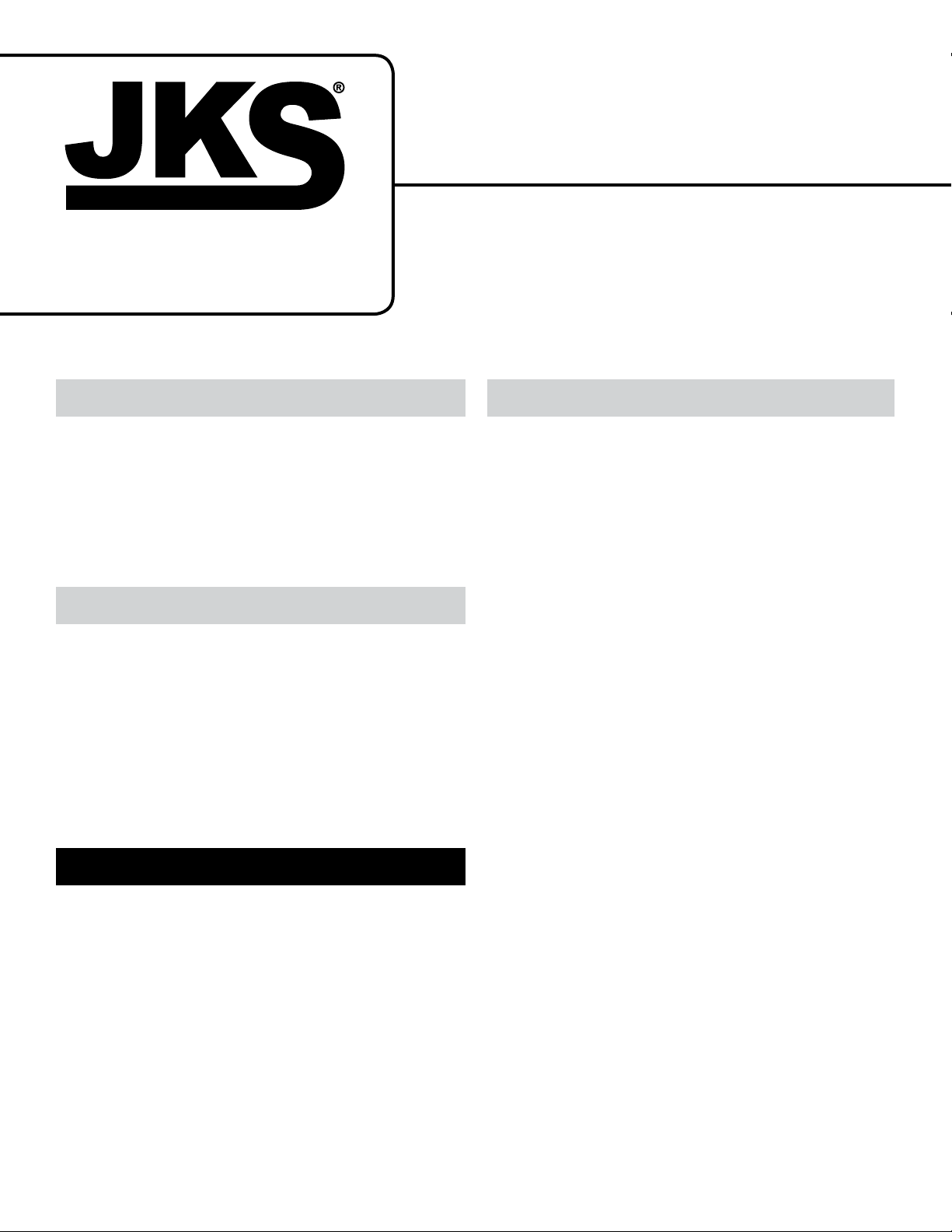
JKS2770JKS ACOS Pro™ Installation Page 5
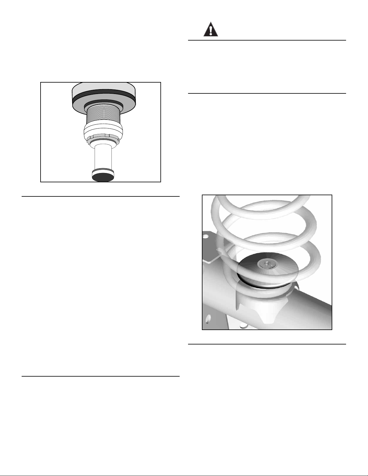
1-1/2” Flathead Socket Screw (K) from spinning,
and tighten the 7/16” Nylock Nut (M) to 50 ft-lbs.
Make sure the Coil Spring Retainer (J) is perfectly
at against the lower spring mount, and coil spring
is secure.
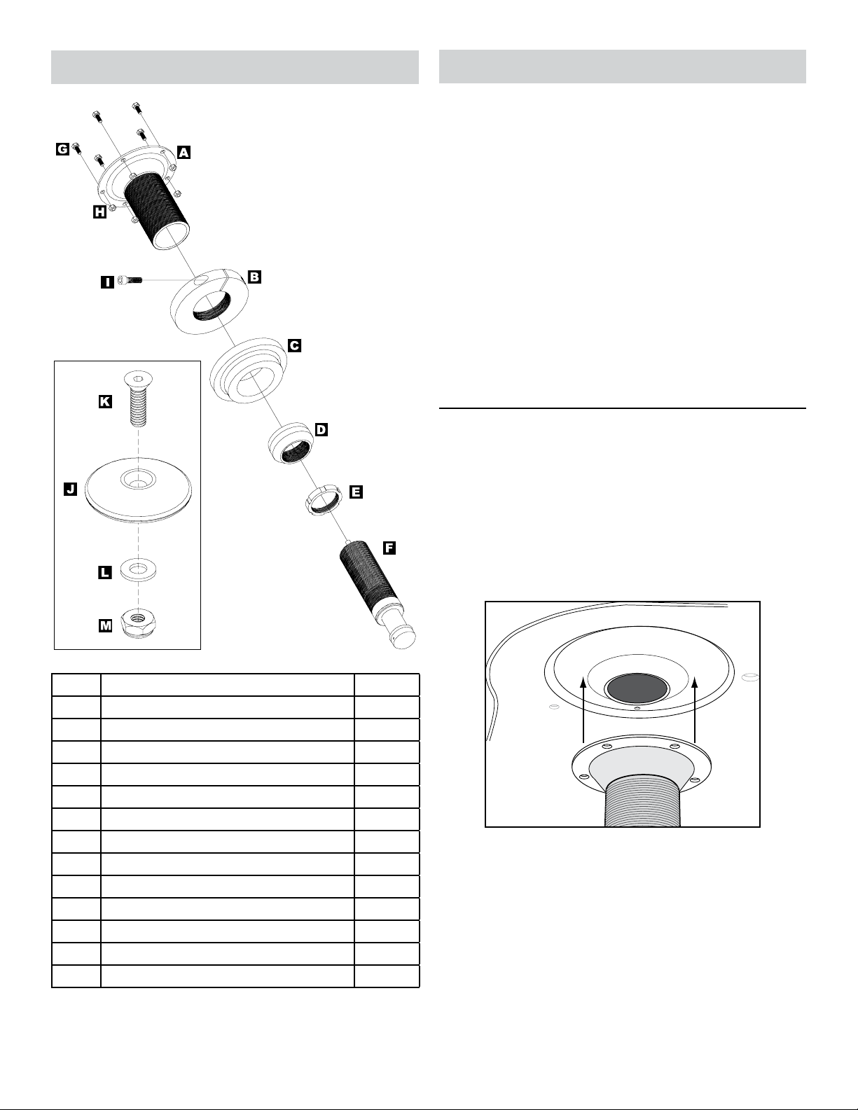
10. ADJUST BUMP SHOCK POSITION
The ideal bump shock position is determined by the vehicle
suspension and varies for each application.
To properly set the bump shock position for your
vehicle, you must rst decide the point at which
suspension compression should be limited. Take
into consideration coil springs, shock absorbers,
tire clearance, or any other factors that cause the
vehicle to bottom out.
IMPORTANT: Because it replaces the original rubber
bump stop, the bump shock should determine the limit
of compression travel. The bump shock should be
fully compressed when the suspension reaches maxi-
mum desired compression.
With the vehicle on level ground and the suspen-
sion at full droop, extend the Bump Shock Assem-
bly (F) to the desired position.
Once the Bump Shock Assembly (F) is properly
adjusted for your application, lock in place by
turning the Bump Shock Nut (E) clockwise until
it contacts the Bump Shock Adapter (D) and fully
tighten to secure adjustment.
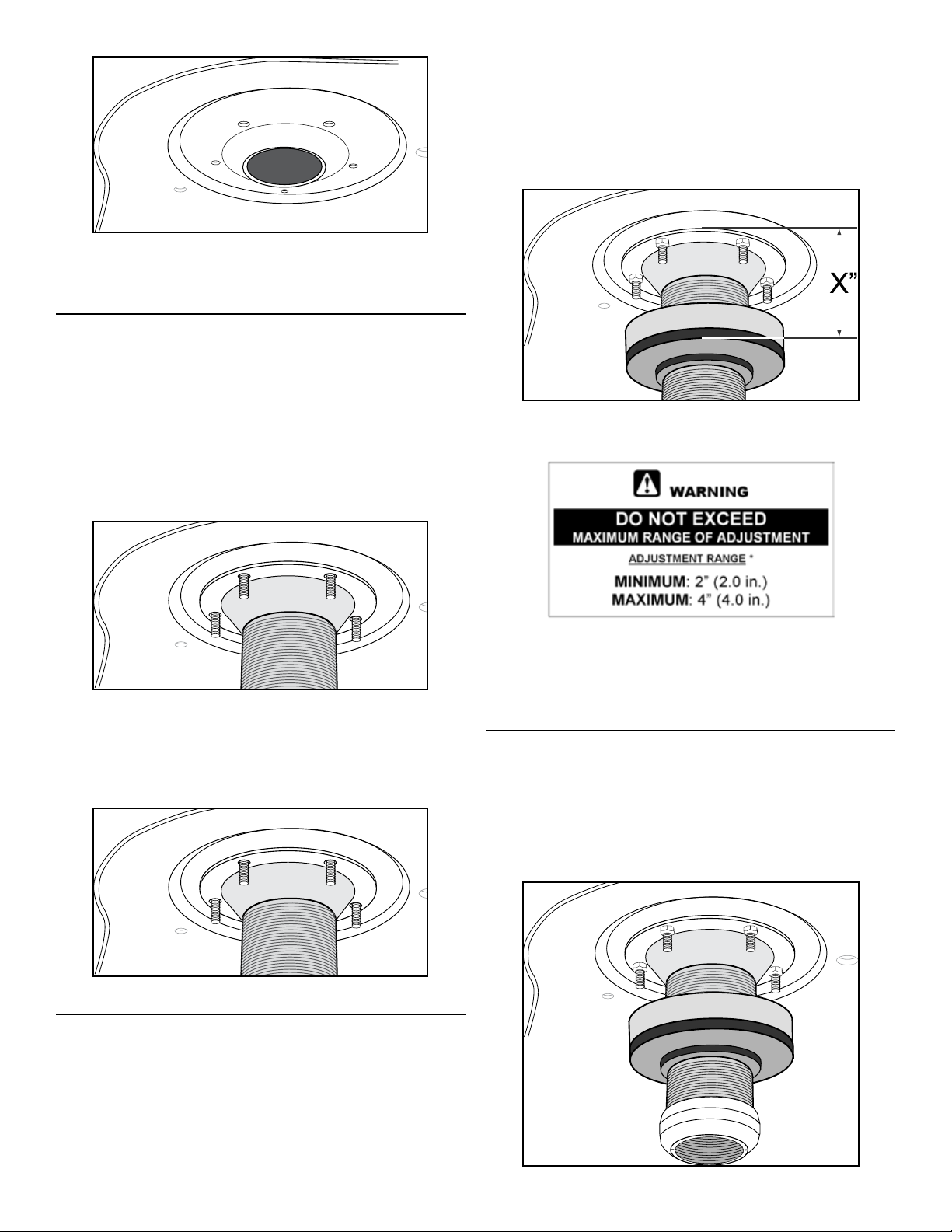
IMPORTANT: The suspension must be fully cycled to
test for bump shock alignment and interference issues
before the vehicle can be safely operated. The bump
shock must contact the center portion of the lower
spring pad at full compression, and there should be no
interference between the bump shock and coil spring
at full extension.
Operation
Ride Height & Bump Shock Adjustments
Future ride height and bump shock adjustments should
be made with NO LOAD on the front coil springs, and the
suspension at FULL DROOP.
NEVER TURN Adjuster Ring (B) while under tension
and ALWAYS APPLY SPRAY LUBRICANT to threads of
Main Body (A) or Bump Shock Assembly (F) before adjust-
ing.
Bump Shock Pressure
The Bump Shock Assembly (F) is pre-charged with the
proper amount of Nitrogen gas to suit most applications.
IT SHOULD NOT BE NECESSARY TO ADJUST BUMP
SHOCK PRESSURE ON MOST VEHICLES.
The Nitrogen charge is factory preset at 150 psi. For ap-
plications that require a higher or lower compression rate,
the gas pressure can be manually adjusted to a minimum
of 100 psi and a maximum of 200 psi.
To adjust pressure, the bump shock assembly must be
removed from the vehicle. Nitrogen pressure is adjusted
through the Schrader valve on top of the bump shock.
Care should be taken when discharging the bump shock to
ensure that no oil is lost. Most shops that service off-road
racing or motorcycle shock absorbers can adjust bump
shock pressure.
Maintenance
Regular cleaning with pressurized water is recommended
to maximize ease of operation and reliability.
In addition, the Bump Shock Adapter (D) has two 1/8”
drainage holes that evacuate any water collected inside the
upper spring retainer. Periodically check for blockages and
clear the drainage holes if necessary.
©2013 JKS Manufacturing, Inc & Aftermarketing, LLC
Revision Date 9/30/2013
Table of contents
Other JKS Automobile Accessories manuals
Popular Automobile Accessories manuals by other brands

iBeam
iBeam TE-FORD-SV-1 installation instructions

Whispbar
Whispbar K700W Fitting instructions

Free2Move eSolutions
Free2Move eSolutions Annex installation manual

Curt Manufacturing
Curt Manufacturing 18153 installation manual

Samsung
Samsung EB-HN910I user manual

Great day
Great day UVRS100BL Instructions for installation and use