JKS PAC2151 User manual

2151JKS Flex Connect Installation Page 1
INSTALLATION
INSTRUCTIONS
Product: Flex Connect Sway Bar Link System
Part Number: PAC2151
Applications: Grand Cherokee WJ, 1999-2004 with 2-4" lift
Welcome
CONGRATULATIONS on purchasing the Flex Con-
nect Sway Bar System from JKS Manufacturing. We
are committed to providing you with the best products
available and your satisfaction is our rst priority.
PLEASE READ these Installation Instructions careful-
ly, and save them for future reference, as they contain
important installation and maintenance information.
Tools Required
Metric/Standard Socket Wrench Set
Grease Gun with Zerk Fitting Coupler
Wheel Bearing Grease
Parts
877-533-7557 • jks@ridefox.com • www.jksmfg.com
491 W. Gareld Avenue, Coldwater, MI 49036
Box Kit - PAC2101 QTY
AFlex Connect Eye 1
BFlex Connect Housing 1
CBushing 1
DSpring Washer 2
ESpring 2
F3/8-16" Nylock Nut 1
GShaft Bushing 1
HRubber O-Ring 1
IPTFE O-Ring 1
JFlex Connect Shaft 1
KFlex Eye 3
LSway Bar Link 1
MJam Nut 1
NGrease Fitting 4
OSpherical Bushing 2
Box Kit - PAC2151 QTY
PPoly Spacer 4
QStainless Steel Post - Male Thread 2
RStainless Steel Post - Female Thread 2
SQuick Pin 4
T1" X 1.40" Spacer 2
U1/2"-20 X 2-1/2" Bolt 2
V1/2" Split Lock Washer 2
W1/2"-20 Nylock Nut 2

2151 JKS Flex Connect Installation
Page 2
WARNING
Higher Rollover Risk
Modifying your Jeep® to improve off-road perfor-
mance may result in vehicle handling different than as
factory equipped, including increased ride-height and/
or chassis articulation; reduced lateral stability and
higher risk of roll-over or other accident. Also, owner’s
choice of larger tire and wheel combinations may
require additional braking force or increased stopping
distances.
To reduce risk of serious injury and accident:
ÂChoose modications that balance your actual
highway & off-road use.
ÂAvoid sharp turns, abrupt maneuvers or steep
side-cambers.
ÂAvoid other maneuvering conditions which may
cause the vehicle to trip, roll, lose traction or com-
promise your ability to safely brake in an emer-
gency.
ÂRoutinely inspect your vehicle components for un-
usual wear or off-road damage. Repair or Replace
any unserviceable components before use.
ÂAcquaint any other drivers with your vehicle modi-
cations and handling.
ÂAlways wear seat belts and/or appropriate off-road
restraints, reduce your speed, Tread Lightly©.
Important
Designed for use the factory sway bar. Fitment and
performance with aftermarket sway bars is up to the
installer.
Flex Connect Link Measures 9-3/4" eye-eye. Can be
installed on other applications. Fitment is up to the
installer. If the links being replaced measure longer
than 9-3/4" eye-eye, additional modications may
be required to avoid sway bar inversion in full droop
conditions. Check link position at full suspension
droop before driving. Contact JKS tech support for
additional assistance if this condition exists.
Some vehicles may require extended front brake
hoses or other modications to compensate for ad-
ditional suspension travel.
Installation
1. REMOVE ORIGINAL EQUIPMENT (OE)
SWAYBAR LINKS
Disconnect the sway bar links from both sides of
vehicle at the axle rst (15mm & 18mm).
After both links are disconnected from the axle,
pull down on the sway bar to gain access to the
bolts to disconnect the sway bar links from the
sway bar (18mm). If links are after market, mea-
sure eye-eye length. If they are longer than 9-3/4",
see "Important Notes". Discard links and Hard-
ware

2151JKS Flex Connect Installation Page 3
2. LINK ASSEMBLY
Locate the two black offset spacers (P) in box
kit PAC2151. These will be used to align the Flex
Connect link so that they are vertical.
The Flex Connect and Fixed link from box kit
PAC2101 will be installed with the black offset
spacers in the position as shown in the picture
below.
Adjust the xed link to be of equal length as the
Flex Connect and lock off the jam nut.
Set links aside for later installation.
IMPORTANT: Flex eyes must remain parallel with
each other when the jam nut is tightened.
3. INSTALL UPPER MOUNTING POSTS
All mounting hardware is located in box kit
PAC2151.
Locate the long stainless steel 1/2" upper tapered
mounting post (Q) with the male threaded end.
Mount the upper tapered mount post on the
inboard side of they sway bar, ensuring the small
Click Pin holes are horizontal or parallel with the
ground.
IMPORTANT: The Flex Connect links must be
mounted inboard of the sway bar for tire clear-
ance.
Apply medium strength threadlock to the tip of the
mounting post threads.
Secure the mounting posts to swaybar by installing
1/2" nylock nuts (W) from the outboard side and
tighten to 65 ft-lbs using a torque wrench.
Hint: A small Phillips head screwdriver or punch in-
serted into the Click Pin hole will enable you to pre-
vent the mounting post from rotating when tightening
the nut.
4. INSTALL LOWER MOUNTING POSTS
Locate the original lower drop link U-bracket on
the axle housing. Insert the gold colored steel OE
Bracket Spacer (T) into the U-bracket.
IMPORTANT: The supplied OE Bracket Spacers
must be installed to prevent the U-bracket from
collapsing when the mounting bolt is tightened.
Apply medium strength threadlocker to the tip of
1/2"-20 x 2-1/2" bolt (U).
Insert the 1/2"-20 x 2-1/2" bolt with 1/2" lock wash-
er (V) completely through the holes in U-bracket
and OE Bracket Spacers from the outboard side of
the bracket.
Thread the tapered Stainless Steel Post (R) on to
the 1/2"-20 x 2-1/2" bolt from the inboard side of
the U-bracket, ensuring small Click Pin holes are
horizontal or parallel with the ground.

2151 JKS Flex Connect Installation
Page 4
Insert Click Pin as illustrated to secure.
IMPORTANT: When properly installed, the ring on
the Click Pin will "snap" against the shaft of the
pin. When installed backwards, the ring does not
t snugly against shaft.
HINT: Lanyard kits (PN 2039) are sold separately to
hold the sway bar up when the Flex Connect links are
disconnected.
6. FINAL INSTALLATION STEPS
Check that torque on all 1/2" bolts is 65 ft-lbs.
Lubricate all grease ttings on the link eyes im-
mediately after installation using a grease gun and
non-petroleum based grease.
Troubleshooting
If swaybar does not rotate freely, remove from vehicle,
clean and apply rubber lubricant to chassis-mounted
bushings, and reinstall.
Tighten the 1/2"-20 x 2-1/2" bolt to 65 ft-lb using a
torque wrench.
Hint: A small Phillips head screwdriver or punch
inserted into the Click Pin hole will enable you to
prevent the tapered Stainless Steel Post from rotating
when tightening the mounting bolt.
5. INSTALL FLEX CONNECT LINKS
Pull the sway bar down to gain access to the upper
mounting posts.
Retrieve the Flex Connect and Fixed links.
Install the Flex Connect link on the passenger
side and the Fixed link on the driver side. This will
ensure adequate clearance throughout suspension
travel.
Slide the upper end of the Flex Connect links onto
the tapered Stainless Steel Posts on both the
driver and passenger sides, ensure that the spac-
ers are in place.
Push the sway bar back up and slide the lower end
of the Flex Connect on both the driver and passen-
ger sides onto the tapered Stainless Steel Posts

2151JKS Flex Connect Installation Page 5
Maintenance
It is important to lubricate the ex eyes frequently for
the rst three (3) months after installation to evacu-
ate contaminants that may build up during break-in
period.
After break-in period, the ex eyes should be lubricat-
ed regularly as part of vehicle maintenance schedule.
Regular cleaning with pressurized water is recom-
mended to maximize ease of operation and reliability.
Always lubricate afterwards to evacuate any moisture
Flex Connect Rebuild
The internal components of the Flex Connect are
sealed and designed for maintenance free long term
performance. These instructions are provided as a
reference for the steps required to swap springs. The
Flex Connect Performance Spring Kit is sold separate-
ly as part number 2100.
1. FLEX CONNECT DISASSEMBLY
These instructions are written with the assumption
the customer has the assembly wrenches included in
the Performance Spring Kit. If not, 2 crescent wrench-
es with jaw openings up to 1-1/2" can be used.
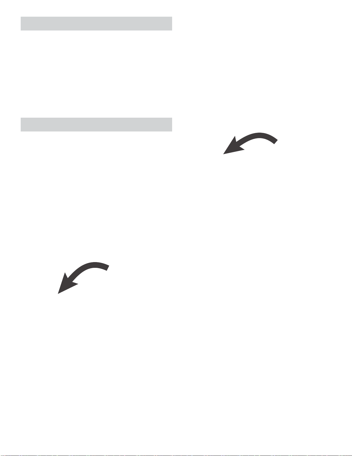
Hold the body of the Flex Connect across the ats
and loosen the Flex Connect body as shown in the
Figure.
Note: A 3/8" rachet can be inserted into the square
hole in the wrench if additional leverage is required.
Note: If using a vice, put the cap in the vice jaws and
use the provided wrench on the body to prevent the
vice from binding on the threads.
With the cap unthreaded, slide the shaft assembly
out of the body.
Tip the Flex Connect body up and the spring fol-
lowed by the washer will fall out of the body.
To remove the spring from the shaft, hold the shaft
across the ats next to the bronze bushing and
remove the nut.
Note: The wrench with the rounded opening is 1/2"
across the ats for the rod and the other is 9/16" for
the nut.
Slide the spring off of the shaft.
Note: The spring washer goes on the side of the
spring towards the cap.
2. FLEX CONNECT ASSEMBLY
Install the washer back into the body of the Flex
Connect followed by the spring of your choosing.
Install a matching spring onto the Flex Connect
shaft followed by the bronze bushing and nut
Torque the nut to 25 ft-lbs.
IMPORTANT: Always install matching springs into the
Flex Connect. Failure to do so will create different roll
stiffness depending on the direction of roll and yield
undesirable handling characteristics.
Apply grease to the bronze bushing if it was re-
moved during disassembly
Slide the Flex Connect shaft back into the housing
and slide the cap down the shaft until the threads
engage.
Tighten the cap to approximately 25 ft-lbs.

2151 JKS Flex Connect Installation
Page 6
©2019 JKS Manufacturing
Revision Date 6/28/2019
Table of contents
Other JKS Automobile Accessories manuals

JKS
JKS OGS125 User manual

JKS
JKS HD X-Member User manual

JKS
JKS ACOS Pro JKS2770 User manual

JKS
JKS JKSOGS122 User manual

JKS
JKS SuperNerfs OGS825 User manual

JKS
JKS PN 6155 User manual

JKS
JKS PN 2400 User manual

JKS
JKS Quicker Disconnects User manual

JKS
JKS Steering Brace System User manual

JKS
JKS 2944 User manual
Popular Automobile Accessories manuals by other brands

Volkswagen
Volkswagen 1K0 071 126 Fitting instructions

rockymounts
rockymounts LOBALL TRACK instructions

Mont Blanc
Mont Blanc RF 26 Fitting instructions

Actia
Actia TGU-R ACCESS user manual

Fishbone Offroad
Fishbone Offroad FB22016 installation instructions

VDO
VDO DTCO 1381 Operating instructions company & driver