manuals.online logo
Brands
  1. Home
  2. •
  3. Brands
  4. •
  5. JL Audio
  6. •
  7. Automobile Accessories
  8. •
  9. JL Audio Stealthbox SB-F-SUPRCNSL/8W7 User manual

JL Audio Stealthbox SB-F-SUPRCNSL/8W7 User manual

INSTALLATION GUIDE
for the
SB-F-SUPRCNSL/8W7
SB-F-SUPRCNSL/8W7
2008-Up Ford Super Duty Trucks
with front bucket seating
Thank you for choosing a JL Audio Stealthbox®for your automotive sound system. With proper
installation, your new vehicle-specific enclosed subwoofer system will deliver years of listening pleasure.
We strongly recommend that you have your new Stealthbox®installed by your authorized JL Audio
dealer. The installation professionals employed by your dealer have the necessary tools and experience
to disassemble and reassemble your vehicle properly. Also, keep in mind that your warranty coverage
extends to 2 years if your system is installed or approved by your authorized JL Audio dealer. If you
prefer to perform your own installation, please read this installation guide completely
before beginning the process.
If you choose to perform the installation yourself, it is absolutely vital that
the Stealthbox®be properly mounted to the vehicle according to these
instructions. Failure to mount the enclosure properly presents two problems:
1) The sub-bass performance will suffer due to the movement of the enclosure
caused by the force exerted by the woofer(s).
2) A loose enclosure presents a serious safety hazard in the event of a collision
or sudden deceleration.
STEP 1
Remove all contents from the center console.
Remove the center console from the truck.
Keep the mounting bolts that secure the console to the
floor. These are to be reused in future steps.
Continued on Next Page
STEP 2
Remove the lid.
STEP 3
Remove the front panel / cup holders
SB-F-SUPRCNSL2/8W7_INSTR_SKU#011249
INSTALLATION
DIFFICULTY:
4
5
OUT
OF
ESTIMATED TIME:
23 HOURS
23 HOURS
Continued on Next Page
SB-F-SUPRCNSL2/8W7_INSTR_SKU#011249
STEP 7
Turn the bottom section of the storage console, to expose
the bottom side.
Mark the two areas shown in the picture. With a cut off
wheel or similar tool, cut out these two sections.
STEP 6
Remove the top section of the storage console.
STEP 5
Remove the side panels.
STEP 4
Remove the rear panel / cup holders.
Page 2 • JL Audio, Inc 2007
The front section of this storage console will need to
be removed. Read STEPs 9-11 to have a complete
understanding of the proper procedure on the removal of
this front section.
STEP 9
Flip the storage console, so the top side is up.
Starting at the front left of the storage console.
Mark the line shown in the picture, top to bottom.
STEP 11
Ending at the front right of the storage console.
Mark the line shown in the picture, top to bottom.
With a cut off wheel or similar tool, cut on the marked lines
from STEPs 9-11.
STEP 10
Looking from the bottom.
Working from the left side to the right side of the storage
console, continue the marking as shown in the picture.
STEP 8
The console is still turned to expose the bottom.
Mark the two areas shown in the picture. With a cut off
wheel or similar tool, cut out these two sections.
Continued on Next Page
SB-F-SUPRCNSL2/8W7_INSTR_SKU#011249
STEP 14
Use the right side wall as a cutting guide, when cutting
down the right side corner. This is to make sure the cutting
tool is only cutting the necessary area. You do not want to
cut into the outer wall.
STEP 13
With an air saw or similar tool, cut out the marked section.
Use the left side wall as a cutting guide, when cutting down
the left side corner. This is to make sure the cutting tool is
only cutting the necessary area. You do not want to cut into
the outer wall.
STEP 12
Mark the area shown in the picture.
STEP 11
Remove the 12v plug from the inner area of the storage
console.
Page 3 • JL Audio, Inc 2007
STEP 16
Flip the bottom section of the storage console, to expose
the bottom side.
Mark the area (dash lines) shown in the picture.
STEP 18
Flip the storage console over.
Place the Stealthbox into the modified storage console.
STEP 17
On both side of the storage console, measure 6-inches from
the back wall to the front and mark. Shown in the picture.
Measure 10-inches from the middle of the rear wall to the
front and mark. Shown in the picture.
Staring at the 6-inch mark on both side of the console,
mark an continues curve to the 10-inch mark. Shown in the
picture.
With a cut off wheel or similar tool, cut on the marked lines
from STEPs 16-17.
STEP 15
Turn the storage console to expose the rear.
At the top right area, measure and mark 2-inches from top to
bottom. At the right side, measure and mark
2 1/2-inches from right to left.
Use a 3-inch hole saw or similar cutting tool, cut on the
marked circle.
6-inches 6-inches
10-inches
2-inches
2-inches
9 1/2-inches
3/4-inches 3/4-inches
2-inches
2-inches
2 1/2-inches
2 1/2-inches
3-inch
3-inch
diameter
diameter
Continued on Next Page
SB-F-SUPRCNSL2/8W7_INSTR_SKU#011249
STEP 21
Using the supplied hardware, secure one of the L-brackets to
the right side of the Stealthbox®. The longer side of the
L-bracket runs down to the Stealthbox® threaded insert.
STEP 20
Flip the Stealthbox / storage console around. Make sure that
the woofer will not rub against storage console, when the
woofer is in motion.
Trim the storage console around the woofer, if necessary.
STEP 19
Secure the top section with he removed factory screws from
STEP 6.
STEP 18
Place the top section of the storage console back onto the
bottom section, around the Stealthbox.
Page 4 • JL Audio, Inc 2007
STEP 23
From inside the truck, place the supplied A-bracket to the
front mounting bar, that is located on the transmission
hump.
Grab a pair of factory bolts that were removed in STEP 1.
Thread in the pair of factory bolts through the A-bracket, into
the factory mounting bar. Only thread in about a 1/4 of the
bolt into the mounting bar.
STEP 25
Place the supplied mounting plate behind the rear mounting
bar as shown in the picture. The mounting plate’s mounting
holes need to reflect what is seen in the picture.
STEP 24
Make sure the ignition is shut off.
To the rear of the transmission hump there is a silver box. At
the rear left corner area, you will see a grounding terminal
that is bolted to the floor. Remove this bolt and terminal and
secure the terminal to the floor by using the left rear
mounting bolt of the silver box, as shown in the picture.
Keep the terminal’s mounting bolt for future step.
STEP 22
Using the supplied hardware, secure one of the L-brackets to
the left side of the Stealthbox®. The longer side of the
L-bracket runs down to the Stealthbox® threaded insert.
Continued on Next Page
SB-F-SUPRCNSL2/8W7_INSTR_SKU#011249
STEP 29
Using two of the factory bolts that were removed in
STEP 1, secure both L-brackets to the rear mounting bar.
Leave these bolts loose.
STEP 28
Run speaker wire from the amplifier’s location to the
Stealthbox® and check for proper operation of the woofer.
STEP 27
Place the Stealthbox® / storage console into the truck.
STEP 26
Slide the mounting plate under the rear mount bar.
The front holes need to line up to the factory thread holes,
behind the silver box. Use the factory bolt that was removed
in STEP 24 to secure the front left side of the plate. Use
supplied hardware to secure the front right side of the plate.
Use the supplied hardware to secure the rear of the plate to
the rear mounting bar.
Page 5 • JL Audio, Inc 2007
STEP 31
Fully tighten the two factory bolts that secure both
L-brackets to the rear mounting bar, from STEP 29.
STEP 33
Place the left side panel of the console that was removed in
STEP 5 between the Stealthbox®/storage console and the
left seat.
Place a supplied foam panel between the side panel and the
Stealthbox®/storage console.
Mount the left side panel onto the Stealthbox®/storage
console.
STEP 32
Place the right side panel of the console that was removed
in STEP 5 between the Stealthbox®/storage console and the
right seat.
Place a supplied foam panel between the side panel and the
Stealthbox®/storage console.
Mount the right side panel onto the Stealthbox®/storage
console.
STEP 30
Lift the front of the Stealthbox® up, place the supplied bolt
from under the A-bracket into the threaded insert of the
Stealthbox®. Tighten the bolt to the Stealthbox®.
Fully tighten the two factory bolts that secure A-bracket to
the mounting bar, from STEP 23.
SB-F-SUPRCNSL2/8W7_INSTR_SKU#011249
CONGRATULATIONS
You have completed the installation for this model!
Please refer to the Power Recommendation section for an
amplifier recommendation and basic set-up help.
STEP 36
Secure the lid of the factory console, from STEP 2.
STEP 35
Secure the rear panel of the factory console, from STEP 4.
STEP 34
Secure the front panel of the factory console, from STEP 3.
Page 6 • JL Audio, Inc 2007
All specifications are subject to change without notice. “JL Audio®” and the JL Audio logo, “Stealthbox” and the Stealthbox logo are registered
trademarks of JL Audio, Inc.“Ahead of the Curve”and its respective logo is a trademark of JL Audio, Inc.
JLA-SKU#011249 -10-26-200
7
7• Printed in USA • ©2007 JL Audio, Inc. • U.S. PATENTS: #5,734,734 #5,949,898 #6,118,884 #6,229,902
#6,243,479 #6,294,959 #6,501,844 #6,496,590 #6,441,685 #5,687,247 #6,219,431 #6,625,292 #D472,891 #D480,709 Other U.S. & Foreign
patents pending. For more detailed information please visit us online at www.jlaudio.com.
(954) 443-1100
www.jlaudio.com
10369 NORTH COMMERCE PARKWAY • MIRAMAR, FLORIDA • 33025 • USA
INCLUDED HARDWARE
(3)
(3)
3/8-inch x 1-inch Hex Tap Bolt
(3)
(3)
1/4-inch USS Flat Washer
(1)
(1)
A-bracket
A-bracket
(3)
(3)
3/8-inch Split Lock Washer
(2)
(2)
L-bracket
L-b rac ke t
(3)
(3)
3/8-inch Flat Washer
(1)
(1)
Plate Bracket
Plate Bracket
(3)
(3)
1/4-inch Lock Washer
(3)
(3)
1/4-inch 20 x 1-inch Bolt
(3)
(3)
1/4-inch -20 Hex Nut
(2)
(2)
6-inch x 12-inch x 3/4-inch Foam
SPECIFICATIONS
Enclosure Type:
Acoustic Suspension (sealed)
Driver Type:
8W7-3
8W7-3
Nominal Impedance:
3 ohms mono
3 ohms mono
Continuous Power Handling:
300 Watts
300 Watts
P O W E R R E C O M M E N D A T I O N
POWER RECOMMENDATION
JL Audio recommends using a high quality amplifier such as the JL Audio 250/1v2.
The diagram below shows the recommended crossover, infrasonic filter and equalizer settings for the 250/1 when
being used to power your Stealthbox®.
The JL Audio 250/1v2 is a very versatile audio component. Please consult the owner’s manual for even more
detailed information about installing and tuning this amplifier.
MID/HIGH FREQUENCY DRIVER FITMENT
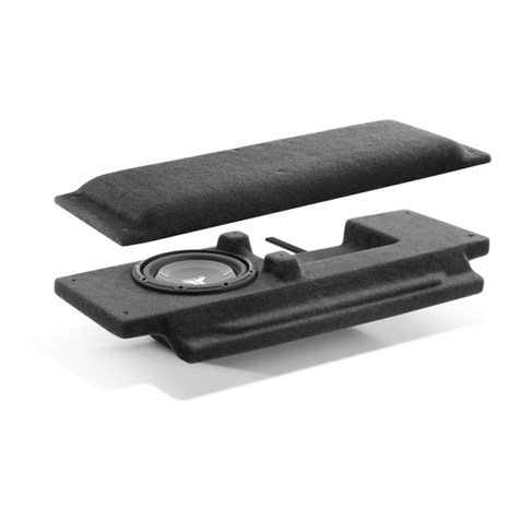
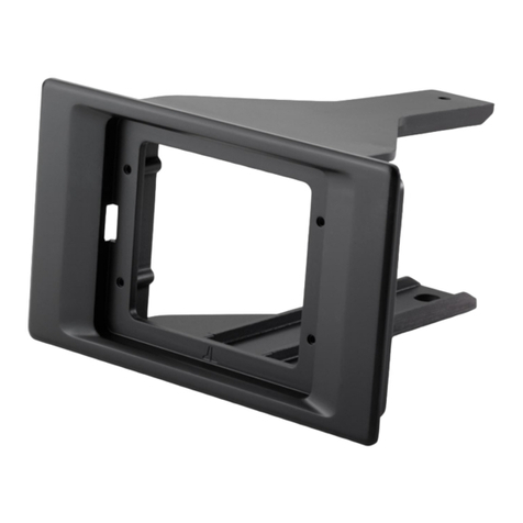
A variety of JL Audio coaxial and component systems will fit in the factory speaker locations of you vehicle.
Front Speaker Size / Location:
5-inch x 7-inch/ Front Doors
Fits JL Audio Models:
TR570-CXi, C5-570, C5-570x & ZR570-CSi
Rear Speaker Size / Location:
5-inch x 7-inch/ Rear Door
Fits JL Audio Models:
TR570-CXi, C5-570, C5-570x & ZR570-CSi

Other JL Audio Automobile Accessories manuals

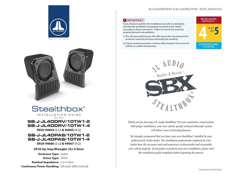
JL Audio Stealthbox SBA-POL-RZG2-DK-MM50 User manual

JL Audio

JL Audio Stealthbox SBA-POL-RZG2-DK-MM50 User manual

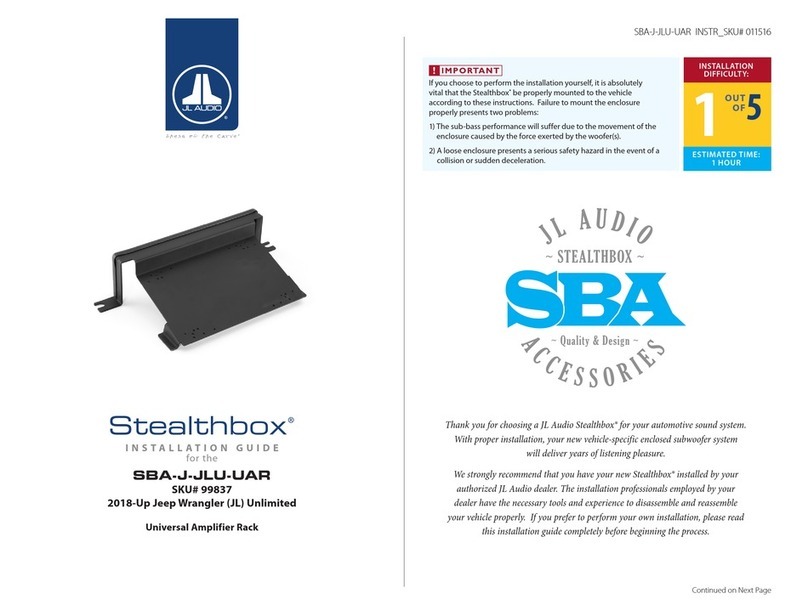
JL Audio Stealthbox SBA-J-JLU-UAR User manual

JL Audio

JL Audio Stealthbox SBA-J-JLU-UAR User manual

JL Audio Stealthbox SBA-J-JKU-UAR User manual

JL Audio

JL Audio Stealthbox SBA-J-JKU-UAR User manual

JL Audio Steathbox SB-GM-SLVD/10TW1 User manual

JL Audio

JL Audio Steathbox SB-GM-SLVD/10TW1 User manual

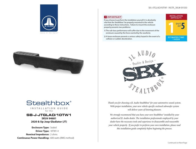
JL Audio Stealthbox SB-J-JTGLAD/10TW1 User manual

JL Audio

JL Audio Stealthbox SB-J-JTGLAD/10TW1 User manual

JL Audio Stealthbox SB-J-JK2DR/10W1v2 User manual

JL Audio

JL Audio Stealthbox SB-J-JK2DR/10W1v2 User manual

JL Audio Stealthbox SB-J-JL4DDRV/10TW1-2 User manual

JL Audio

JL Audio Stealthbox SB-J-JL4DDRV/10TW1-2 User manual

JL Audio Stealthbox SB-GM-VETC6/10W3v2 User manual

JL Audio

JL Audio Stealthbox SB-GM-VETC6/10W3v2 User manual

JL Audio 13W7-D1.5 User manual

JL Audio

JL Audio 13W7-D1.5 User manual

JL Audio Stealthbox SB-T-TACACG3/10TW3 User manual

JL Audio

JL Audio Stealthbox SB-T-TACACG3/10TW3 User manual

JL Audio Stealthbox SB-H-PIO7/10TW3 User manual

JL Audio

JL Audio Stealthbox SB-H-PIO7/10TW3 User manual

JL Audio 94512 User manual

JL Audio

JL Audio 94512 User manual

Popular Automobile Accessories manuals by other brands

Briefkasten Manufaktur Basic Charger operating instructions

Briefkasten Manufaktur

Briefkasten Manufaktur Basic Charger operating instructions

Juice Booster 2 user manual

Juice

Juice Booster 2 user manual

CrimeStopper SV-6712 reference guide

CrimeStopper

CrimeStopper SV-6712 reference guide

Fiamma HYMER ADAPTER KIT 02 Installation and usage instructions

Fiamma

Fiamma HYMER ADAPTER KIT 02 Installation and usage instructions

Spyder Auto PRO-YD-CM04 Series installation guide

Spyder Auto

Spyder Auto PRO-YD-CM04 Series installation guide

Dynojet Power Commander III USB installation guide

Dynojet

Dynojet Power Commander III USB installation guide

Kuda-Phonebase 296010 Installation instruction

Kuda-Phonebase

Kuda-Phonebase 296010 Installation instruction

Cruz 909-454 Assembly instructions

Cruz

Cruz 909-454 Assembly instructions

Leer Velocity installation instructions

Leer

Leer Velocity installation instructions

Tuff Tonneaus 11303 FITTING INSTRUCTION

Tuff Tonneaus

Tuff Tonneaus 11303 FITTING INSTRUCTION

Prorack K949 Fitting instructions

Prorack

Prorack K949 Fitting instructions

EAL LAS 10112 operating instructions

EAL

EAL LAS 10112 operating instructions

M7 R56 installation guide

M7

M7 R56 installation guide

aFe Power Magnum FORCE 54-13035D instruction manual

aFe Power

aFe Power Magnum FORCE 54-13035D instruction manual

Roadmaster Sterling All Terrain owner's manual

Roadmaster

Roadmaster Sterling All Terrain owner's manual

STO N SHO SNS 312 Installation procedures

STO N SHO

STO N SHO SNS 312 Installation procedures

EUFAB JAKE operating instructions

EUFAB

EUFAB JAKE operating instructions

Hamron 619604 operating instructions

Hamron

Hamron 619604 operating instructions

manuals.online logo
manuals.online logoBrands
  • About & Mission
  • Contact us
  • Privacy Policy
  • Terms and Conditions

Copyright 2025 Manuals.Online. All Rights Reserved.