JLG 6308AN User manual

6308AN Lighting Tower
www.jlg.com.au
131 JLG
Hydraulic articulated
tilt jib to position lights
horizontal or vertical
Steel cabinets with
lockable latches
Long extension wind down outriggers
that stow away for transport
4 lifting lugs for
easy lift by crane
Hydraulic articulated main boom lift
Hydraulic telescopic mast to
increase height to 8m and to
increase outreach
Sylvania local supply 1500W
double end mount lamps.
Adjustable pan and tilt to provide
flexible lighting area
Forklift pockets for ease of transport and site positioning

6308AN Lighting Tower
www.jlg.com.au
131 JLG
APPLICATIONS
• Construction
• Mining
• Plumbing
• Roadworks
• Specialevents
• Emergencyservices
QUESTIONS TO ASK
• Whatisthelightingapplication–mining,roadworks,sportseld,
construction,specialevent?
• Doyouhavealightingplan?
• Doyouneedautostop/startormanualstart?
• Doyouhaveasetuplocationselectedanddoyouknowthe
siteconditions?
• Howisthedeliverytothesiteorganised,towingormultipleunits
onatrucktray?
KEY SELLING POINTS
• Retractabledrawbarforsidebysideloadingontransporttray
• 1personsetup–outriggers
–hydraulicarticulatedmast
–liftandtelescopeandtiltmast
–1handmanualrotation
–4adjustablepanandtiltlights
• Largefueltankformultipleshiftoperationplusextendedshiftwith
autostop/start
• LocalsupplyofSylvaniaandClipsalcomponents
• Tiltheadlightsareabletobedirectedstraightuporstraightdown
• Lightheadstowsabovedrawbarforprotectionoflightsduring
transport and to reduce travel height
• 6308abletobeusedasgeneratorunitduringdaylighthours
SPECIFICATIONS
Height Stowed 2.40m
Length Stowed 2.50m
Width 1.75m
Weight Gross Max. – Full Tank 1,530kg
Mast Max. Elevation 8.00m
Mast Max. Horizontal Outreach 3.00m
Mast Rotation 350˚ Non-continuous
Engine Perkins 403D-11 0A
Fuel Type Diesel
Engine Power @ 1500rpm 8.6kW
Generator 13kVA
Lights Metal Halide
Light Power 6000W (4 x 1500W)
Wheels 16” x 6J Rims
Tyres 205/80 x 16”
Max. Wind Speed Rating 32m/s
Max. Towing Speed 80km/h
Fuel Tank Capacity – Steel 167 Ltr
Mast System
Lift Hydraulic
Telescopic Hydraulic
Tilt Hydraulic
Rotate Manual
Hydraulic System Power 12 Volt DC

6308AN
ISO 9002 Lic 6080
www.jlg.com.au
Operator & Safety
Service & Maintenance
Illustrated Parts
Manuals
Issue: April 2004 PRINTED IN AUSTRALIA 1730616

6308AN
CONTENTS
Section One ........................... Operator and Safety
Section Two ........................... Service and Maintenance
Section Three ........................... Illustrated Parts
Section Four ........................... Recommended Spares Quick Reference
Customer Support
JLG Industries (Port Macquarie)
11 Bolwarra Road
PORT MACQUARIE NSW 2444
Phone: (02) 6581 1111
JLG Industries (Victoria)
549 Blackburn Road
MOUNT WAVERLEY VIC 3149
Phone: (03) 9545 6303
JLG Industries (Queensland)
1/23 Collinsvale Street
ROCKLEA QLD 4106
Phone: (07) 3272 9988
JLG Industries (Western Australia)
49-53 Poole Street
WELSHPOOL, PERTH WA 6106
Phone: (08) 9356 9811
JLG Industries (NSW)
23 Christina Road
VILLAWOOD NSW 2163
Phone: (02) 9726 6511
JLG Industries (Hong Kong)
Room #7, Level 11, Landmark North
39 Lung Sum Avenue
Sheung Shui, NT, Hong Kong
Phone: +85 2 2639 5783
JLG Industries (Korea)
Hyosung Villa 14-201
590-25, Banpo 4 dong, Seocho Ku
Seoul, Korea, 137-044
Phone: +82 2 3486 6523
JLG Industries (India)
G-62 Kothi,
Saket, New Delhi 110 017
India
Ph: +91 1 1652 5507
JLG Industries (SA) Agent:
State Access Crane
9 Pentland Road
SALISBURY SOUTH SA 5106
Phone:
(
08
)
8283 1099
JLG Industries (New Zealand)
64-66 Huia Road
Otahuhu, Auckland
New Zealand
Phone: + 64 9276 1728

6308AN
INTRODUCTION
This manual provides the information necessary for the safe operation and
maintenance of the JLG Model 6308AN Lighting Tower.
Specific operating details and specifications are contained in this publication to
familiarise the operator and maintenance personnel with the correct and safe
procedures necessary to maintain and operate this equipment.
A detailed Illustrated Parts Manual is also provided to easily identify the component
parts required for service and maintenance purposes.
Take time to read this book thoroughly. If you are uncertain about any of the
information presented, contact your JLG Service Office before operations
commence.
All instructions in this manual are based on the machine being used under the
operating conditions for which it was designed. In reading this manual, particular
attention should be given to safety related Cautions and Warnings. Proper use and
care will see this machine providing years of reliable service.

6308AN
SECTION ONE
OPERATORS AND SAFETY MANUAL
CONTENTS
Page
• General 1-1
• Safety precautions 1-2
• Preparation for use 1-5
• Delivery and periodic inspection 1-5
• Controls identification 1-6
• Machine set up/pack up instructions. 1-8
• Forklifting machine 1-11
• Craning machine 1-11
• Towing Instructions 1-12

Page 1-1
6308AN
GENERAL
This section prescribes the proper and safe practices for machine operation. In order
to promote proper usage of the machine, it is mandatory that a daily routine be
established based on the regular maintenance schedule in the service and
maintenance section of this manual. A maintenance program shall also be
established by a qualified person and should be followed to ensure that the machine
is safe to operate.
The user/operator of the machine shall not accept operating responsibility until this
manual has been read and operation of the machine under the supervision of an
experienced and qualified operator has been completed. If there is a question on
application and/or operation, JLG Industries Customer Support Department should
be consulted on (02) 6581 1111 (Australia).
MODIFICATION OF THE MACHINE WITHOUT THE PRIOR WRITTEN APPROVAL
OF JLG INDUSTRIES (AUSTRALIA) IS PROHIBITED.
!

Page 1-2
6308AN
SAFETY ALERT SYMBOLS AND SAFETY SIGNAL WORDS
This is the Safety Alert Symbol. It is used to alert you to the
potential personal injury hazards. Obey all safety messages
that follow this symbol to avoid possible injury or death.
!
!
INDICATES AN IMMINENTLY HAZARDOUS SITUATION. IF NOT
AVOIDED, WILL RESULT IN SERIOUS INJURY OR DEATH. THIS
DECAL WILL HAVE A RED BACKGROUND.
INDICATES A POTENTIALLY HAZARDOUS SITUATION. IF NOT
AVOIDED, COULD RESULT IN SERIOUS INJURY OR DEATH.
THIS DECAL WILL HAVE AN ORANGE BACKGROUND.
!
INDICATES A POTENTIALLY HAZARDOUS SITUATION. IF NOT
AVOIDED, MAY RESULT IN MINOR OR MODERATE INJURY. IT
MAY ALSO ALERT AGAINST UNSAFE PRACTICES. THIS DECAL
WILL HAVE A YELLOW BACKGROUND.
!
INDICATES PROCEDURES ESSENTIAL FOR SAFE OPERATION.
THIS DECAL WILL HAVE A GREEN BACKGROUND.

SAFETY PRECAUTIONS
6308AN
SAFETY PRECAUTIONS
This section outlines the safety
precautions applicable to the general
use of this product.
Throughout the Operator and Safety
section of this manual, cautions and
warnings are shown in BOLD TYPE.
These outline where special care is
required when undertaking the various
procedures outlined.
NOTE: The safety precautions
applicable to the service and
maintenance of the machine are
covered in the SAFETY
PRECAUTIONS section of the Service
and Maintenance Manual.
The user of this machine should read
this manual thoroughly to ensure that
all operating procedures are clearly
understood prior to accepting
responsibility.
• Modifications or alterations to the
lighting tower are not permitted
without the prior written permission
of the manufacturer.
• Failure to comply with the safety
precautions listed here and
elsewhere in the manual may result
in injury or death.
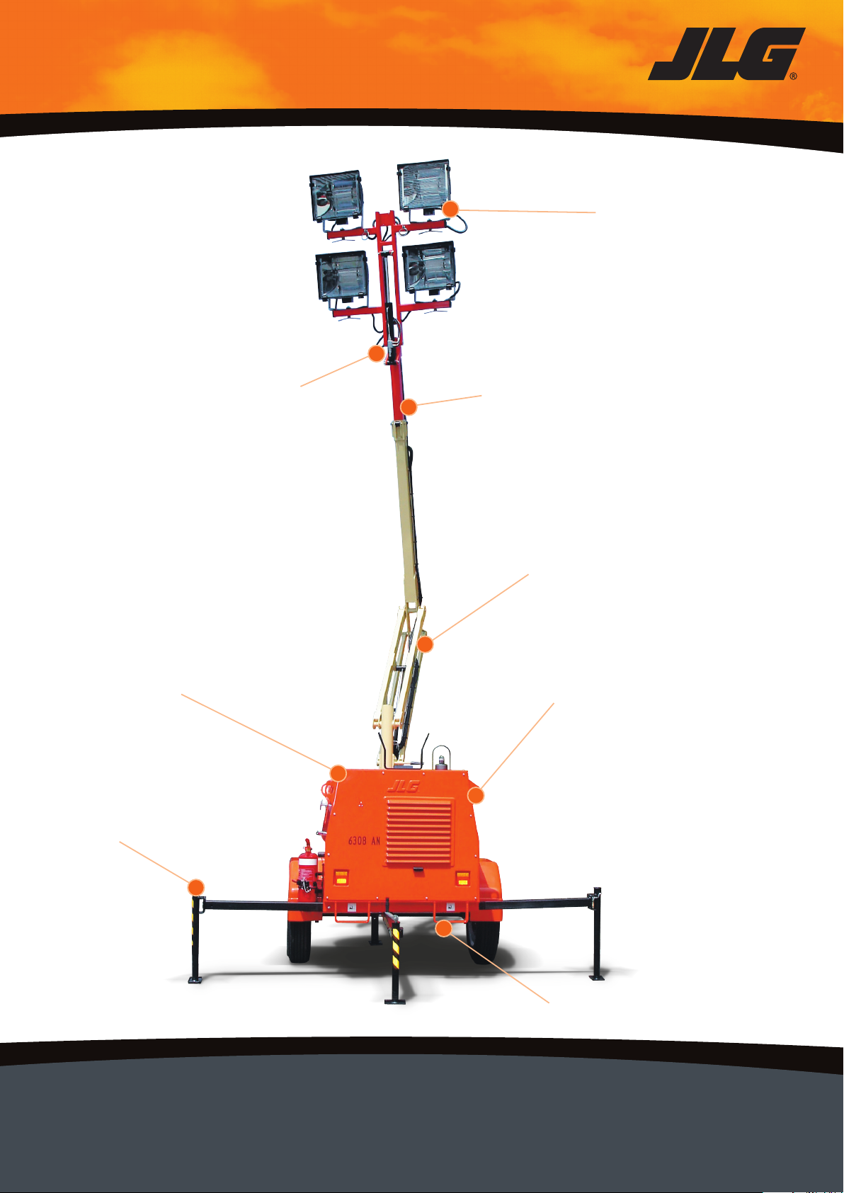
• When handling the lighting tower
other than towing for the purposes
of lifting or manoeuvring, there are
forklift pockets provided at the rear
of the machine and 4 lifting points
provided on the main frame for
lifting by a crane. Ensure that the
forklift or crane is of suitable e lift.capacity prior to attempting th
Refer to the diagrams shown
elsewhere in this manual for correct
handling procedures using a crane
and forklift.
• Prior to erecting the mast the
operator should ensure that no
overhead obstructions are within a
6-metre radius of the base of the
machine.
THERE IS ELECTROCUTION
HAZARD TO THE OPERATORS
IF THE MACHINE IS OPERATED
NEAR OVERHEAD
POWERLINES.
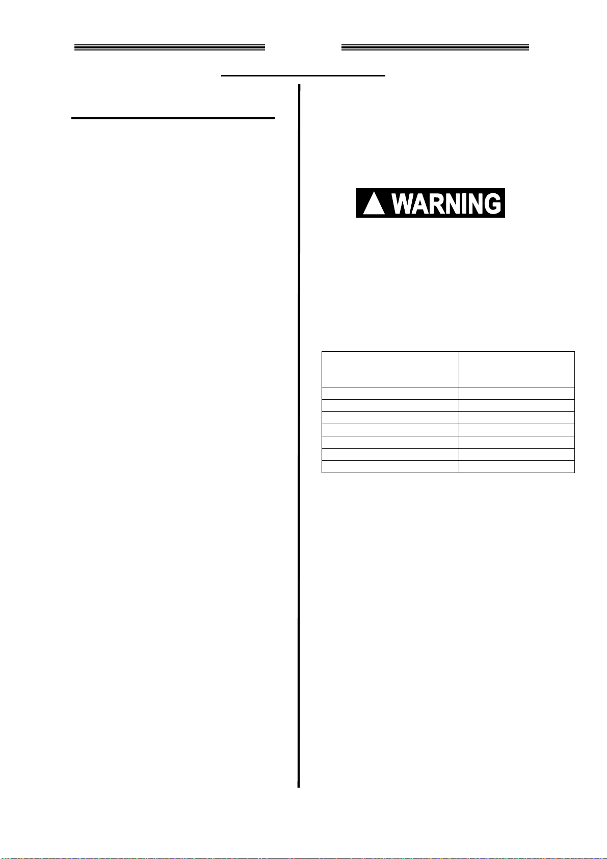
The following chart is a guide to the
applicable safe operating distances
from overhead power lines.
!
Voltage Range
(Phase to Phase) MINIMUM SAFE
DISTANCE
In Metres (Feet)
0-300V AVOID CONTACT
Over300-50 KV 3 (10)
Over 50 KV to 200 KV 5 (15)
Over 200 KV to 350 KV 6 (20)
Over 350 KV to 500 KV 8 (25)
Over 500 KV to 750 KV 11 (35)
Over 750 KV to 1000 KV 14 (45)
Be aware of the radius of the mast
when telescoped out and lowered.
Be aware of swaying power lines
and swaying tree branches in
strong winds.
• Be familiar with all controls on the
machine prior to operation. The
machine incorporates powerful
hydraulic mechanisms that can
cause serious mechanical damage
if the machine is allowed to strike
external structures such as
buildings etc.
• Ensure that the ground is suitable
to support the machine, particularly
under each of the outrigger pads. A
suitable packing material such as a
timber block may be required on
soft surfaces to ensure that the
outriggers do not sink under the
weight.
Page 1-3

SAFETY PRECAUTIONS
6308AN
FAILURE OF THE OUTRIGGER
TO SUPPORT THE MACHIN
DUE TO SOFT SURFACES
COULD CAUSE THE MAC
TO TIP OVER IN
S
E
HINE
WINDY
ONDITIONS.
• Tipping of the
R
LLING OF THE
•
ll and electrical devices.
trained service
• rd in any way
• e
•
•
• r is
he 4
•
intenance, checks or
accessing the engine area ensure
engine is shut down and the mast
retracted.
Page 1-4
C
Do not erect the machine in winds
greater than 118kmh.
machine is possible.
NEVER RAISE THE MAST
FULLY WITHOUT FIRST
SETTING ALL 4 OUTRIGGERS
AND ENSURING THE LIGHTING
TOWER IS LEVEL. A BUBBLE
LEVEL IS MOUNTED AT THE
FRONT OF THE MACHINE NEA
THE BASE OF THE MAST TO
AID IN LEVE
MACHINE.
The model 6308AN Lighting Tower
incorporates an A.C. alternator
which generates lethal voltages. Do
NOT operate the machine without
all safety covers in place covering
a wiring
DO NOT TOUCH LAMP
TERMINALS OR SOCKETS.
DANGEROUS VOLTAGE MAY BE
PRESENT EVEN WHEN POWER
IS OFF. Shutdown engine, switch
off all circuit breakers, and allow
10-minutes for ballast capacitors to
discharge before replacing lamps.
Check capacitors are below 10VDC
before service to lamp sockets or
ballast circuits by
personnel only.
Do not alter the electrical wiring
type, size or standa
without prior written approval from
the manufacturer.
The lighting tower is NOT a mobil
generator set. It should only be
used for the specific purpose for
which it was designed.
The hydraulically operated mast
has hazardous crushing/pinch
points. Do NOT put arms, hands
etc. near the mast structure while it
is in operation.
The metal halide lamp fixtures can
get extremely hot during operation.
Do not operate the lights in easy
reach of people’s hands. Even after
lights have extinguished, the lamp
fixtures can remain hot for up to 20
minutes.
The mast of the Lighting Towe
designed specifically to carry t
lights supplied. Alternative lights
should not be adopted unless
specifically authorised by the
manufacturer.
• The mast is not a crane. Do not
attempt to lift any objects by using
the mast and hydraulic system.
There are moving parts in and
around the engine and alternator
area of the unit. Prior to carrying
out any ma
!
!
!

PREPARATION FOR USE
Page 1-5
6308AN
PREPARATION FOR USE
Before a new machine is put into
operation it must be carefully inspected
for any evidence of damage resulting
from shipment.
Note: Regular periodic inspections are
a required aspect of the ongoing
maintenance of the machine.
Preparation for use of the machine
requires good common sense
principles ensuring that a complete
function check together with visual
inspections show that everything is
working correctly.
Function checks are to include the
following items.
1. Outriggers slide in and out freely.
2. Outrigger Jacks operate freely.
3. Operation of the 3 mast hydraulic
levers in both directions to ensure
free correct movement of the mast.
Prior to use, all fluid levels should be
checked including
• Radiator coolant
• Engine oil level
• Fuel level.
Ensure that all warning decals have
been read and understood prior to
perating machine.o
Ensure that machine set up location is
clear of any dangers such as roadways
with moving traffic, moving machinery
tc.e
Some locations may require that
checks are made with the regulatory
authority such as councils prior to the
et up and use of this lighting tower.s
Ensure that machine is securely
parked prior to use. Barriers, fences
and warning signs may need to be
erected to ensure awareness of the
unit in operation.
DELIVERY AND PERIODIC
INSPECTION
This machine requires periodic safety
and maintenance inspections by a
qualified person.
Particular attention is required during
checks to ensure that the machine
functions as it was designed to. There
should be no abnormal noises or
vibrations evident during the machine’s
operation. In the event that an operator
becomes aware of any abnormal
operation while using the machine,
then it should be shutdown
immediately, stowed safely and the
problem reported to a responsible
supervisor or service technician.
Reference should be made to Section
2 (Service and Maintenance) for
procedures in regular and periodic
inspections of this machine. All
machines require both preventive and
corrective maintenance throughout
their useful service life to maintain the
machine in a safe and reliable
condition.

CONTROLS IDENTIFICATION
6308AN
CONTROLS IDENTIFICATION
Engine Control Panel
1. Ignition on – emergency shutdown
switch.
2. Service light switch for optional
cabin light.
3. Circuit breaker 15 Amp protects
D.C. control circuits.
4. Circuit breaker 20 Amp master D.C.
circuit protection.
5. Alternator warning light. This light
will illuminate if loss of alternator
charge is experienced.
6. On some units without an engine
shutdown system, this is a low
engine oil pressure warning light.
On units retrofitted with an Engine
Shutdown System this is an Engine
distress light indicating, low oil
pressure, low water level, high
engine temperature condition.
7. Keyswitch. Turn left for engine glow
preheat. The glow plug light will
illuminate and then extinguish after
a few seconds. Then turn the key to
the right to start the engine.
8. Glow plug light as described in item
7.
9. Hourmeter. Shows number of hours
that the machine has been on.
10.Engine shutdown timer module.
11.Timer duration selector switch.
12.Timer on/off switch.
13.Start Override Switch.
Engine Shutdown Unit
Located within the above control box is
an engine monitoring shutdown
system. In the event that one of the
following conditions should take place,
the engine will shutdown and illuminate
the Engine Distress Light.
1. Low oil pressure
2. Low water level
3. High engine temperature
Should a shutdown occur, the system
can be reset by turning off the ignition.
The fault should be corrected prior to
restarting.
Light Control Panel
1. A.C. Main Circuit Breaker and
Residual Current Device (R.C.D)
provides overload protection to all
A.C. circuits connected to the
Alternator.
2. Switch/circuit breaker for lights one
to four. Also protects against
overload on these lights.
3. R.C.D/circuit breaker for General
Purpose Outlet A.C. (G.P.O) option
when fitted.
1
25
34
10
6
7
8
9
1 2 3
11
12
13
Page 1-6

CONTROLS IDENTIFICATION
6308AN
Hydraulic Controls for Mast
1. Mast raise and lower control lever.
Pushing forward or pulling back will
raise and lower the mast
respectively. Speed of the raise
and lower function can be
controlled by pushing or pulling the
lever further away from the centre
off position.
2. Telescope in/out control lever.
Operating this lever will telescope
the upper boom extend in and out.
3. Tilt mechanism control lever.
Operating this lever will allow the
light bar head to be tilted up and
down for aiming lights. It is also
used when stowing the mast to
ensure the lighting bar head is
tucked in for transport.
4. Hydraulic controls Enable Switch
which must be pressed during the
operation of any of the hydraulic
control levers.
Mast Rotate Mechanism
1. Mast rotate locking Mechanism.
Rotate this knob counter-clockwise
to release mast lock prior to
rotating.
2. Mast Rotate Handle. Use this
control to manually rotate mast
through 350 degrees to desired
position. Ensure mast lock is
rotated clockwise to lock mast prior
to use.
3. Mast rotate lockpin. This pin is
spring loaded into the locked
position. It must be pulled out prior
to rotating mast. The pin locks the
mast every 15°. The mast may be
locked in any position by using the
rotate lock, however, in
exceptionally high winds the mast
may move slightly if it is positioned
between the 15°lockpin indents. It
will move to the nearest lockpin
position and the lockpin will engage
to prevent further movement.
Park Brake
The park brake handle shown above
acts on the hydraulic master cylinder. It
is locked into position by the ratchet
locking bar. To apply the park brake,
pull the handle forward and lock the
ratchet bar into place as shown.
PRIOR TO TOWING THE VEHICLE,
ENSURE THE PARK BRAKE IS
RELEASED AND THAT THE
123
Park Brake
4
1. Rotate
Lock
!
3. Rotate
Lock
p
in 2. Rotate
Handle
Page 1-7

CONTROLS IDENTIFICATION
6308AN
RATCHET BAR IS SWUNG WELL
OUT OF THE WAY. FAILURE TO DO
THIS COULD CAUSE THE BRAKES
TO LOCK ON DURING TOWING.

MACHINE SET UP AND PACK UP
6308AN
MACHINE SET UP AND PACK UP
INSTRUCTIONS
The following setup instructions are
applicable when the Light Tower is
towed into position. When the machine
is transported by truck and then
forklifted into position, ensure that the
retractable drawbar is extended and
pinned prior to setup and raising the
mast. Failure to do so may affect the
stability of the machine under some
operating conditions. The front
outrigger leg may then be lowered to
support the front of the machine and
the transport leg raised and pinned in
the upper position. Do not use the
transport leg to support the machine
when raising the mast.
Machine Setup Instructions
1. Select a flat level area to park the
machine.
2. Ensure parking brake is applied
prior to unhitching unit, removing
safety chain and electrical cable.
3. Lower the front outrigger jack to
take the weight of the unit. Raise
unit until it unhitches from the
towing vehicle. Drive the towing
vehicle forward clear of the draw
bar.
4. Lower the front outrigger jack down
until the draw bar is sloping forward
slightly.
5. At the rear of the unit, locate and
slide out the left outrigger arm and
lock pin into position. Rotate the
jack from the stowed position
through 180°until the foot is just
above the ground. Turn the jack
handle to lower the foot against the
ground.
6. Repeat step 5 for the right hand
outrigger arm and jack.
7. Raise the front of the machine by
adjusting the front outrigger jack
until the machine is level and each
outrigger support jack is pressing
firmly against the ground. Located
behind the flip up number plate is a
fourth outrigger leg. Release the
remote locking pin and flip up the
number plate. Withdraw the
outrigger leg outwards to the locked
position approx. 0.7 metre. Rotate
the outrigger leg through 90
degrees and adjust by turning the
handle clockwise until the leg is in
firm contact with the ground.
(Approx. 2 turns after contact). Do
not attempt to jack up the machine
by overextending.
It is not necessary to raise the
wheels of the machine off the
ground when lowering the
outrigger jacks. When set up
correctly the wheels may still be in
firm contact with the ground. If the
surface is uneven though, one
wheel may need to be raised off
the ground to level the machine.
A bubble level is provided on the
front of the machine to assist in
levelling.
Page 1-8

MACHINE SET UP AND PACK UP
6308AN
8. Ensure that the light bar assembly
is clear to swing out and away from
its stowed position. Unlatch the
transport turnbuckles.
PRIOR TO RAISING THE MAST,
CHECK AND ENSURE THAT NO
OBSTRUCTIONS ARE LOCATED
ABOVE THE UNIT TO A HEIGHT
OF 10 METRES. REFER ALSO
TO SAFE DISTANCES FROM
POWER LINES AS DESCRIBED
IN SECTION 1 (SAFETY
PRECAUTIONS).
9. Slowly operate the light bar tilt
hydraulic lever and hydraulic
controls enable switch to move the
light bar forward, up and away from
the front of the tow hitch.
10.Operate the lift control lever and
hydraulic controls enable switch to
continue to raise the mast to full
elevation.
11.Operate the telescope lever and
hydraulic controls enable switch to
extend the mast to desired height.
12.Finally, adjust the light bar tilt to the
desired angle by operating the tilt
control lever and hydraulic controls
enable switch.
TO AVOID CRUSHING INJURY,
KEEP HANDS AND ARMS AWAY
FROM THE MOVING PARTS OF THE
MAST.
Turning Lights On
!
1. Start the engine by switching on the
ignition switch, turning the key
counter-clockwise to the Glow
Preheat position until the Glow
Light extinguishes and then turning
to the right to start the Engine.
Once started, allow the engine to
warm for a minute prior to using.
NOTE: The Engine Distress
Shutdown system if installed
requires a build up of engine oil
pressure before the engine will
start. To overcome a delay in
starting, a momentary pushbutton
called “Start Override” is located on
the control panel below the Engine
Distress Light. Hold this button in
when cranking engine to start.
2. Switch on main circuit breaker.
Then switch on the light circuit
breakers 1, 2, 3 & 4 to activate
lights.
3. Allow lights to warm up and reach
full brightness (about 3 minutes).
NOTE: The lamps used are a Metal
Halide Gas Discharge type. If they
are switched off and back on again
after they have been running they
may take up to 15 minutes to re-
ignite. This is normal for this type of
lamp.
!
Page 1-9

MACHINE SET UP AND PACK UP
6308AN
Machine Pack Up
Packing up the machine for towing or
transport is a reversal of the setup
steps. Take special care when
lowering the boom and ensure it rests
neatly in the boom cradle at the rear of
the machine.
Ensure the light bar is stowed in
towards the mast and is locked against
the stop prior to towing.
The light bar tilt mechanism is
hydraulically locked into place during
transport. However, for added safety 2
turn buckles attached to the front of the
machine provide rigid support for
extended transport. The turnbuckles
need only be tightened “lightly” to
provide adequate support.
When retracting the rear outrigger
legs, ensure that they are pinned and
locked in the retracted position. Rotate
the outrigger jack 180 degrees and
turn the handle so that the jack pulls
down lightly on the rubber anti shake
pads as shown below.
Page 1-10

LIFTING MACHINE
Page 1-11
6308AN
FORKLIFTING MACHINE
Forklifting Procedure
WHEN USING A FORKLIFT TO
MOVE THE MACHINE ONLY THE
FORKLIFT POCKETS LOCATED AT
THE REAR OF THE MACHINE
SHOULD BE USED.
Prior to using a forklift to lift the
machine, ensure that the mast is
lowered to the stowed position, the
lights are stowed and the engine
generator is shut down.
The machine weighs approximately
1700kg. Ensure that only a suitable
forklift with adequate capacity is used
to lift the machine.
When positioning the forklift forks into
the forklift pockets, ensure the forks go
through far enough to pick up the fork
support bar located across the main
frame of the unit. Fork penetration
should be at least 800mm from the
rear wall of the light tower.
CRANING MACHINE
Craning Procedure
USE ONLY THE 4 LIFTING POINTS
PROVIDED TO LIFT THE LIGHTING
TOWER WITH A CRANE. DO NOT
LIFT THE ASSEMBLY BY THE
MAST. DOING SO WILL RESULT IN
SEVERE DAMAGE TO THE UNIT
AND POSSIBLE INJURY TO THE
PERSONNEL UNDERTAKING THIS
TASK.
The mast and lights should be in the
stowed position and the engine
generator shut down prior to lifting the
machine off the ground. Ensure all
outrigger legs and the draw bar are in
the retracted and locked position.
Using suitable lifting equipment
attached to the lifting lug at each
corner of the machine, proceed to lift
the machine as per the instructions
provided for the lifting crane.
!
!

TOWING INSTRUCTIONS
Page 1-12
6308AN
PRIOR TO TOWING THE LIGHT
TOWER UNIT THIS MANUAL
SHOULD BE READ AND
UNDERSTOOD.
THE LIGHT TOWER HAS A GROSS
VEHICLE MAXIMUM WEIGHT OF UP
TO 1700 KGS. ENSURE THAT THE
TOWING VEHICLE AND TOW BAR
ARE RATED TO TOW A VEHICLE OF
THIS WEIGHT SAFELY.
THE STANDARD TOW COUPLING IS
2 INCH 51MM BALL TYPE. OTHERS
ARE AVAILABLE AS AN OPTION ON
REQUEST. THE LIGHT TOWER
USES A HYDRAULIC OVERRIDING
BRAKE MECHANISM. YOU SHOULD
MAKE SURE YOU UNDERSTAND
THE OPERATION OF THIS
MECHANISM PRIOR TO USE.
FAILURE TO PROPERLY ENGAGE
THE OVERRIDING BRAKE
MECHANISM COULD CAUSE THE
VEHICLE TO GET OUT OF
CONTROL AND CAUSE DEATH OR
SERIOUS INJURY.
Prior to Towing
• Ensure that machine is shut down,
the mast correctly stowed and
access doors closed.
• Retract and stow the rear
outriggers.
• Ensure the extendable tow bar is
extended and locked.
• Attach the Light Tower to the
towing vehicle and ensure ball
coupling is locked in.
• Attach the safety chain.
• Connect and test the lights
including turn indicators and brake
lights.
• Disconnect the hand brake by
unlocking and swinging the toothed
ratchet up and towards the rear.
• Swing the front outrigger leg up into
the horizontal stowed position.
!
• Ensure that the overriding brake
lockout mechanism is swung up to
allow brakes to work.
NOTE: For reversing the unit the
overiding brake lockout mechanism
may need to be swung down to
prevent brakes being applied when
reversing.
• Move off slowly and apply the
brake gently to test the coupling
and brake action.
Handbrake Handbrake
Lock Coupling
!
Overriding Brake
Lockout Lever

Created with an evaluation copy of Aspose.Words. To discover the full versions of our APIs
please visit: https://products.aspose.com/words/
Evaluation Only. Created with Aspose.Words. Copyright 2003-2021 Aspose Pty Ltd.
Table of contents
Other JLG Lighting Equipment manuals
Popular Lighting Equipment manuals by other brands

Frankfurt Laser Company
Frankfurt Laser Company FLTT Series manual

Proline
Proline 66186 operating manual

EuroLite
EuroLite LED D-12 Beam Effect user manual

Home Accents Holiday
Home Accents Holiday TY756-1614-1 Assembly instructions

Springdale Lighting
Springdale Lighting STA11265 Assembly instructions

SCHOTT
SCHOTT DCR III user manual

Cooper
Cooper 1555-CSA quick start guide

LUXX LIGHTING
LUXX LIGHTING 645w LED PRO user manual

Wagan
Wagan Brite-Nite Wayfinder LED Light user manual

Godox
Godox LED308W II instruction manual

Vision & Control
Vision & Control R-CLR-100x73-G523-SL Installation and operating instructions

B-K lighting
B-K lighting MINI-MICRO RECESSED UPLIGHT installation instructions