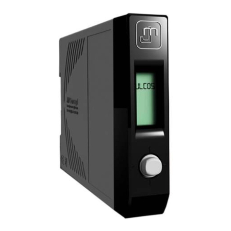
JM Concept TELIS 9000 User manual

Operating manual
TELIS 9000
Version of 03/30/2023

Operating manual TELIS 9000
2/ 86
Summary
Technical characteristics..........................................................................................................................................................................3
Safety precautions ..................................................................................................................................................................................12
Dimensions and wiring ...........................................................................................................................................................................14
Installation ..............................................................................................................................................................................................17
Programming and key functions............................................................................................................................................................21
Programming by PC ................................................................................................................................................................................23
Error messages........................................................................................................................................................................................24
Main menu...............................................................................................................................................................................................25
Measurements menu 1 input..................................................................................................................................................................27
Measurements menu 2 inputs ................................................................................................................................................................29
Measurements menu 2 inputs + calculation..........................................................................................................................................31
Simulation function ................................................................................................................................................................................33
Input menu..............................................................................................................................................................................................35
Calculated input configuration ..............................................................................................................................................................37
Current input configuration 1 input.......................................................................................................................................................40
Current input configuration 2 inputs .....................................................................................................................................................44
Voltage input configuration....................................................................................................................................................................47
Potentiometer input configuration........................................................................................................................................................51
Resistance input configuration ..............................................................................................................................................................55
RTD input configuration .........................................................................................................................................................................57
Thermocouple input configuration........................................................................................................................................................60
Output menu ...........................................................................................................................................................................................63
Alarm menu .............................................................................................................................................................................................66
MODBUS Protocol ...................................................................................................................................................................................71
MODBUS exchange table ........................................................................................................................................................................75
Guarantee certificate ..............................................................................................................................................................................85
UE declaration of conformity .................................................................................................................................................................86

Operating manual TELIS 9000
3/ 86
Technical characteristics
X
X
X
X
X
Universal input

Operating manual TELIS 9000
4/ 86
Presentation
TELIS 9000 is a universal input transmitter with quadruple galvanic isolation, 24-bit conversion for inputs and16-bit
conversionfor outputs, and accurate cold junction compensation at ±1°C for thermocoupleinputs.
TELIS 9000 is guaranteed for 5 years
Range
*: 1 universal input or 2 current passive mA inputs with calculation mode
Transmitter with
graphic display
Input*
Outputs Communication Case width
(mm)
Transmitter without
graphic display
Number of
Analog Number of Relay
1 2 1 2 3 4 RS485 USB 22.5 45
TELIS 9000U0 ✓✓ ✓ TELIS 9000T0
TELIS 9000U1 ✓ ✓ ✓ ✓ TELIS 9000T1
TELIS 9000U2 ✓✓✓ ✓ TELIS 9000T2
TELIS 9100U0 ✓✓✓ ✓ TELIS 9100T0
TELIS 9150U1 ✓ ✓ ✓✓ ✓ TELIS 9150T1
TELIS 9250U0 ✓✓ ✓ ✓ TELIS 9250T0
TELIS 9200U0 ✓✓ ✓✓TELIS 9200T0
TELIS 9200U1 ✓ ✓ ✓ ✓✓TELIS 9200T1
TELIS 9200U2 ✓✓✓ ✓✓TELIS 9200T2
TELIS 9300U0 ✓✓✓✓TELIS 9300T0
TELIS 9300U1 ✓ ✓ ✓✓✓TELIS 9300T1
TELIS 9400U0 ✓✓ ✓ ✓TELIS 9400T0
TELIS 9400U1 ✓ ✓ ✓ ✓ ✓TELIS 9400T1
TELIS 9400U2 ✓✓✓ ✓ ✓TELIS 9400T2

Operating manual TELIS 9000
5/ 86
Factory settings
Input Output 1 & 2 Relays (1 RT or 1T)
4-20mA 4-20mA Alarm: High
Display: 0-100 Threshold: 50
Communication speed: 9600 bauds, Slave address: n°1
Other settings on demand

Operating manual TELIS 9000
6/ 86
Inputs - Outputs
Input gauges
Current (continuous) Standard scales: 0-1mA ; 0-10mA ; 0-20mA ; 4-20mA ; ±1mA ; ±10mA ; ±20mA
Adjustable scales: from -22 to 22mA
Voltage (continuous)
Standard scales: 0-100mV ; 0-1V ; 0-5V ; 1-5V ; 0-10V ; 2-10V ; ±100mV ; ±1V ; ±5V ; ±10V
Standard scales: 0-50V ; 0-100V ; 0-200V ; 0-500V ; 0-1000V ; ±50V ; ±100V ; ±200V ; ±500V ; ±1000V
Adjustable scales: From -110 to 110mV, from -2 to 11V
Adjustable scales: From -1000 to 1000V
Variable resistance
thermometer
Standard scales: CU50 ; CU53 ; CU100
PT10 ; PT100 ; PT1000 ; Ni100 ; Ni1000 2 or 3 wires
Adjustable scales: CU50 ; CU53 ; CU100
PT10 ; PT100 ; PT1000 ; Ni100 ; Ni1000 2 or 3 wires
Resistance 2 wires Standard scales: 200Ω; 1KΩ; 10KΩ; 50KΩ
Special table for NTC PTC Adjustable scales: 200Ω; 1KΩ; 10KΩ; 50KΩProgrammable with IXLOG software
Unit: °C or °F
Thermocouple
Standard scales: J, K, R, S, T, E, B, N, W3/D, W5/C, Mo, P
Adjustable scales: J, K, R, S, T, E, B, N, W3/D, W5/C, Mo, P
Unit: °C or °F
Cold junction compensation: internal or external
Potentiometer From 0-100Ωto 0-100KΩOther values on request
Sensor supply 2 or 3 wires sensor 24V - 32mA max
Only in 1 channel input mode
Output gauges
Output Current 1 & 2 Standard scales: 0-10mA ; 0-20mA ; 4-20mA
Adjustable scales: from 0 to 20mA
Output Voltage 1 Standard scales: 0-10V ; ±10V (except TELIS 9150X1 and TELIS 9300X1) ; 0-5V ; 1-5V ; 2-10V
Adjustable scales: from -10 to 10V (except TELIS 9150X1 and TELIS 9300X1)
Output Voltage 2 Standard scales: 0-5V ; 1-5V ; 2-10V ; 0-10V
Adjustable scales: from 0 à 10V
Output Relay Relay 1RT or 1T: 2A-250Vac
Communication Isolated USB in Front Panel / Isolated RS485 Modbus RTU

Operating manual TELIS 9000
7/ 86
Characteristics
Display
Type Backlit LCD
Color Blue
Number of characters 5
Numbers of lines 5
Programming joystick 5 positions
Input characteristics
Current input impedance 5.6Ω
Voltage input impedance U<10V: >10MΩ
U±10V ou >10V: 6MΩ
Current input PT100 ; Ni100 Current: <1mA
Current input PT1000 ; Ni1000 Current: <0.8mA
Current input resistance 2 wires R=200Ω; R=1kΩCurrent: <1mA
Current input resistance 2 wires R=10kΩCurrent: <0.2mA
Output characteristics
Permissible impedance on the current output Output 1 & 2: <1kΩ
Permissible impedance on the voltage output Output 1 & 2: >1kΩ
Isolation
Supply / Input-Output(s)-Relay- RS485-USB 4200Vrms, 50Hz, 1mn
Input / Output 1 / Output 2 / Relay / RS485 2500Vrms, 50Hz, 1mn
USB / Input 2500Vrms, 50Hz, 1mn
USB / Output 2 Without
USB / Output 1-relay 2500Vrms, 50Hz, 1mn
USB / RS485 2500Vrms, 50Hz, 1mn
Auxiliary source
Voltage supply 22-240Vdc or 90-230Vac 50/60Hz

Operating manual TELIS 9000
8/ 86
General characteristics
Precision class 0.1
Input analog / digital conversion 24 bits
Output analog / digital conversion 16 bits
Response time Process input, Thermocouple, 2 wires resistor: <80ms
RTD potentiometer: <160ms
Thermal drift <25ppm
Residual ripple on current output <20μA
Residual ripple on voltage output <10mV
Maximum of consumption <10VA
Operating temperature -10°C … +60°C
Storage temperature -25°C … +80°C
Protection factor IP20 Black self-extinguishing polyamide housing V0
Options listing
Option Device code
Tropicalization for 22,5mm or 45mm cases TELIS 9XXXXX-T
Auxiliary source 22-60Vac TELIS 9XX9XX
Passive output only on the calibre 4-20mA
Permissible voltage on the passive output:
15V<U<36V
TELIS 9XXXXX-PAS11 (output 1 passive)
TELIS 9XXXXX-PAS12 (output 2 passive)
TELIS 9XXXXX-PAS22 (2 passive outputs)

Operating manual TELIS 9000
9/ 86
Functions
Display functions
LCD display Graphic display by LCD screen
LED indicators 1 green LED on devices without display
5 positions joystick Allows you to configure the parameters displayed on the front panel screen
Programming lock Locking of the programming on the front panel or by the IXLOG software
Unlock by long press on the joystick
Programming Programming via joystick on the front panel, or via USB with IXLOG software
Memory Mini / Maxi Storage of the maximum and minimum value of the measurement on each input
channel
Customizing the display Resolution, Comma, Contrast adjustment, Display off
Input
Inputs display The display allows to visualize the input in physical value and in programmed value
Adjustable input scale Allows to zoom on the input either in manual or automatic mode
Offset Manual adjustment of the input offset
Taring Taring function at process input (by validation)
Cut-off Threshold below which the input is considered as null

Operating manual TELIS 9000
10/ 86
•
•
•
•
Smart functions
Sensor signal loss
Translates the sensor signal loss on:
the display,
each of the analog outputs,
the digital output,
the status of the relays
Filtering Integration of the measurement over the defined time (in seconds)
Calculation mode Rule calculation (+, -, x, /), result on input 3
Square root The output(s) are function of the square root of the input
Absolute value The output(s) are a function of the absolute value of a bidirectional input
Pilot function/simulation
The pilot function makes it possible to act on the display value influencing the
output(s), independently of the input
The Pilot function is activated either by the digital link (RS485 or USB) or by the
joystick on the front panel
Segmentation in 99 points Linearization in 99 points (free choice for each point), allows to create an output
function by segmentation of the signal of each input channel
Segmentation PTC-NTC resistive Allows to create the PTC or NTC curve by segmentation of the input signal
(programmable only by the IXLOG software)
CJC Cold junction compensation by 16 bit digital sensor
Outputs
Visualization of the outputs The display allows to visualize the outputs, in physical value and percentage; as well
as the status of the relays
Output assignment Assignment of outputs to inputs or to the control function, independently for each
channel
Adjustable output scale Allows you to zoom in on the outputs
Output limitation Possibility to limit the value of the outputs - High limit and Low limit
Relay assignment Assignment of relays to inputs or to the control function, independently for each
channel
Thresholds
Single or band mode, with positive or negative safety
Adjustment of thresholds, hysteresis and time delay (independent on rise or fall)
Direct access to the thresholds
Acknowledgement of alarms Independently for each alarm
Storage of alarms and/or relay status Independently for each alarm

Operating manual TELIS 9000
11/ 86
•
•
Links and communication
RS485 MODBUS RTU
RS485 MODBUS RTU bidirectional digital link allowing to:
recover the measurements and transmit them in digital format
configure and control the device
Digital bus Access to the digital bus via the USB socket (when transmitters are used on the
interface boards)
USB front USB front panel to connect directly to the USB port of a PC for programming via the
IXLOG software
Mapping of Modbus addresses Mapping of Modbus addresses, allowing you to choose your own variable address

Operating manual TELIS 9000
12/ 86
Safety precautions
Introduction
To ensure the conditions of quality, precision and safety, the user must carefully read and comply with the rules of assembly and
operation indicated in this manual.
Safety
Qualification of staff
This manual must be read by qualified and authorized personnel in charge of installation, operation, maintenance and cleaning.
Symbols on the product
Triangle with exclamation mark: Read this user manual before operating the equipment to know the nature of the
potential HAZARDS and all the measures to be taken to avoid them
Double insulation symbol: Equipment protected everywhere by DOUBLE INSULATION
CE symbol: indicates that the module complies with the requirements of the CE directives
General safety measures
If the commissioning of the equipment differs from that described by the manufacturer, the protection provided by the
equipment may be impaired. Do not turn on the module under high Voltages until it is fixed.
Any installation that does not correspond to the installation requirements will void the warranty. Any opening of the
product will immediately void the warranty.
If a high voltage is connected to the inputs/outputs of the device, respect sufficient insulation between the wires,
terminal blocks and the housing with the surrounding environment to maintain protection against electric shock.
Handling and maintenance operations must be carried out only by qualified and authorized personnel.

Operating manual TELIS 9000
13/ 86
Receipt and storage of the product
Upon receipt of the device, check that it has not been damaged during transportation
It must be stored in its packaging in a room protected from dust, moisture, and mechanical vibration.
The storage temperature must be between -25°C and 80°C
Maintenance and Repair
To clean any marking on the device, switch off the device and then use a cloth slightly moistened with distilled water.
If a device can no longer be used under optimal safety conditions, it must be taken out of service and protected against
inadvertent use, then returned to JM Concept.
Operating environment
The product must be installed and used indoors, in an electrical box.
It must not be exposed to temperatures outside the limits prescribed for ambient temperatures (-10°C ... +60°C).
The product is not intended to operate at altitudes higher than 2000m.
It can be installed in an environment of pollution degree 2 and withstand transient surges of the power supply network of
Category II.
It can withstand grid fluctuations of +/-10% on its voltage supply. The product is designed for a temporary voltage level between
phase and earth according to EN/IEC61010.
The circuits for measurements, inputs, and outputs are meant for connection to SELV (Safety extra low voltage) circuits only:
60Vdc max / 42.4V peak max / 30Vrms max).
The insulation level of external circuits plugged into the inputs and outputs should be of 2500Vrms in order to maintain the
existing insulation in the device between the different interfaces.
Since the bottom of the product enclosure has openings, it is not considered a fireproof enclosure.
•
•
Never open the case
Repairs are only to be carried on JM Concept's premises.

Operating manual TELIS 9000
14/ 86
Dimensions and wiring
Dimensions
Dimensions: Width : 22.5 or 45 mm - Height: 81 mm - Depth: 98 mm
BASELINEboards are to be ordered separately
22.5 mm Case: Reference BL01ALV ; 45 mm Case: Reference BL02ALV
For multi-transmitter boards, please consult us.

Operating manual TELIS 9000
15/ 86
Wiring
TELIS 9000U0
TELIS 9000U2
TELIS 9150U1
TELIS 9200U1
TELIS 9000U1
TELIS 9100U0
TELIS9200U0
TELIS9200U2

Operating manual TELIS 9000
16/ 86
TELIS 9250U0
TELIS 9300U1
TELIS 9400U1
TELIS 9300U0
TELIS 9400U0
TELIS 9400U2

Operating manual TELIS 9000
17/ 86
Installation
Prerequisite
Mounting of the Baseline on the DIN rail
The baseline shall be mounted vertically on a DIN rail, placed horizontally.
Engage the top of the notch on top of the rail and push the base from the bottom until the plastic hook locks in place.
Mounting of the baseline on the DIN rail
A D-curve circuit breaker or equivalent must be placed close to the base and be easily accessible. This protection device must
allow to cut the voltage of the power supply cables connected to the Baseline. Once the power is cut and the cables removed, the
baseline can be unclipped.
To unclip the baseline from the DIN rail, pull the plastic hook down with a screwdriver, and pull the baseline towards yourself.
•
•
•
•
•
Necessary equipment:
DIN rail
Screwdriver
Copper wire of section 2.5 mm² max
Cutting pliers
Circuit breaker or equivalent
In case of temperature > 40°C or if the DIN rail is mounted in an upright position, a space of 5mm between 2 transmitters
is recommended.
Before installing or removing the baseline on the DIN rail, it must be turned off and the products removed.

Operating manual TELIS 9000
18/ 86
Setting up the transmitter on the baseline
The connection of the 22.5mm device is done by means of screw terminals distributed in 2 rows of 3 terminals marked from 1 to
6, at the top; and 2 rows of 3 terminals marked from 7 to 12, at the bottom.
The connection of the 45mm device is made by means of screw terminals distributed in 2 rows of 6 terminals identified from 1 to
6 and from 13 to 18, at the top; and 2 rows of 6 terminals identified from 7 to 12 and from 19 to 24 at the bottom.
The power supply of the product is done via the baseline on terminals 2 and 3 marked in red.
On other terminals, use a maximum of 2.5 mm² wire.
Strip cables over a length of 6mm
The tightening torque should be 0.6 Nm.
When connecting the power supply to the base, check that the power is turned off to avoid any risk to the operator.
Baseline 45, top view
Baseline 22.5, top view
Baseline, profile view
Use wire section 2.5 mm² for the power supply (2 and 3).

Operating manual TELIS 9000
19/ 86
When the connection of the power supply, outputs and inputs is made, the transmitter module can be installed on its baseline.
Check that the transmitter module is in the right direction and matches the "UP" indication on the baseline.
Insert the product into the slot of the baseline until it is clicks and locks in top and bottom.
The device must be positioned in such a way as to facilitate the disconnection from its baseline, and this allowing the power cut-
off of the module.
The mini-USB socket on the front of the product allows the connection to a PC for the product's configuration software.
Front view: Baseline 22,5mm and Baseline 45mm
If the transmitter has an RJ45 socket on the front panel, it can be connected to the industrial network with an Ethernet cable.
Removing the transmitter module from its Baseline
Press the blue button to unlock the device.
Holding down the blue hook, pull the device out of the base.
Removing the transmitter
The product can be connected or disconnected from its base while powered.

Operating manual TELIS 9000
20/ 86
1.
2.
3.
4.
Power Supply
The product has its own power supply.
The power supply conditions of the product (voltage, frequency, consumption) are available in the following sections "Technical
characteristics" →"Characteristics" →"Auxiliary source" →"Power Supply voltage", and "Technical characteristics" →
"Characteristics" →"General characteristics" →"Maximum consumption" of this document.
Operating Instructions
Before operating the device, make sure you follow the steps below in order:
Install and wire the product, check the baseline (BL) if applicable. Refer to the "Installation" chapter of this manual.
Power the product. Refer to the "Installation" chapter →"Power Supply" of this manual.
Program the inputs/outputs of the product. Refer first to the chapter "Programming and keys functions " of this manual.
Configure the communications. Refer to the "Settings Menu" and "MODBUS Exchange Table" sections of this manual
(depending on the product reference).
Plan a protective fuse to protect the external power supply because the product is not equipped with one.
Install an external protective fuse, time-delayed of type T 500mA 250V with a high cut-off power.
The cut-off power of the protective fuse shall be greater than the short-circuit current that can be supplied by the power
source.
This manual suits for next models
28
Table of contents
Other JM Concept Transmitter manuals
Popular Transmitter manuals by other brands

Becker
Becker Centronic EasyControl EC541-II Assembly and operating instructions

Canon
Canon Wireless File Transmitter WFT-E2 II A instruction manual

Bircher
Bircher RFGate 3.2.T Supplementary sheet to the original instruction manual

FlowLine
FlowLine FloaTek LV55 Series manual

Nulaxy
Nulaxy KM29 user manual

COMECO
COMECO PHG Operation manual