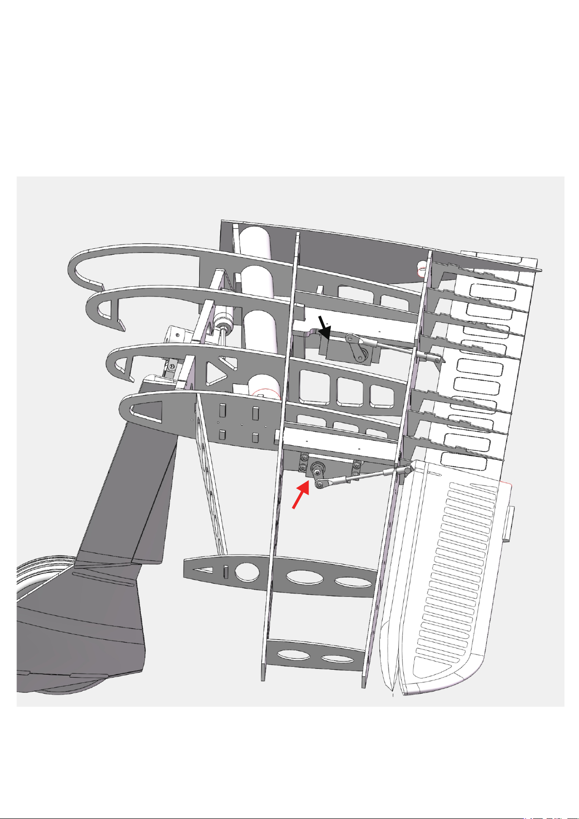
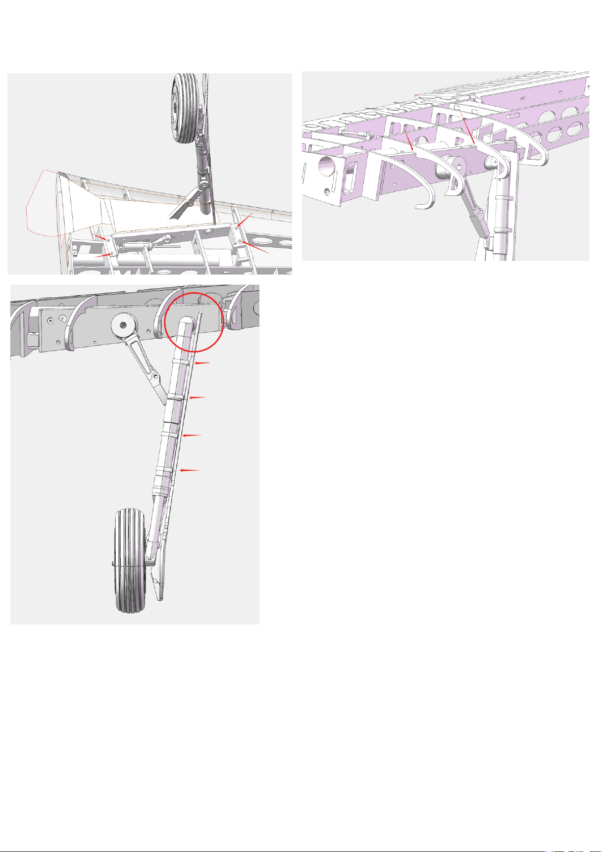
升降舵舵机和推杆安装示意图
Installation diagram elevator servo and the push rod
1
3
4
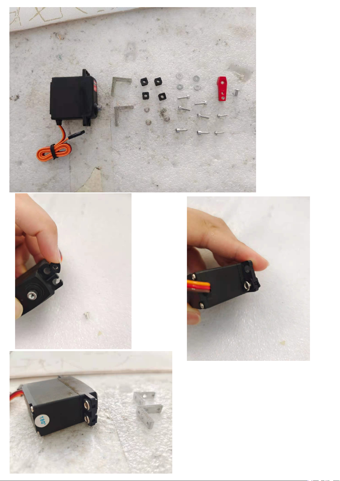
①选用相应尺寸的舵机,如图2 。
②确认好舵机输出轴方位后装入。如图3画红圈位置是舵机电缆伸出来的位置。
然后用螺丝规格:M2.6x14十字自攻螺丝固定,如图1四个红色箭头所示。
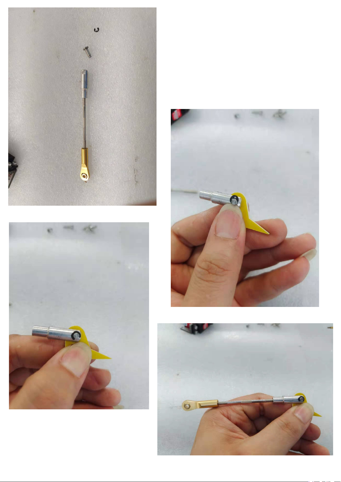
③选用φ2孔径的球头推杆,先安装在圆形舵盘上,如图4红色箭头所标的4个孔
的其中的一个孔,调节适当的长度后装入舵机与舵面连接处。
2
Unit: mm
①Select the servo of the corresponding size, as shown in Figure 2.
②After confirming the position of the output shaft of the steering gear, install it. As
shown in Figure 3, the position of the red circle is the position where the servo cable
extends. Then use screw specifications: M2.6x14 Phillips self-tapping screws to fix,
as shown by the four red arrows in Figure 1.
③Choose a ball head putter with a diameter of φ2 and install it on the circular servo
arm plate first. Adjust one of the four holes marked by the red arrow in Figure 4,
adjust the appropriate length, and install it into the connection between the servo
and the rudder surface.
8