JNF IN.15.702 User manual

INSTALLATION MANUAL / MI0216.1 www.jnf.pt 1/44
IN.15.702 / IN.15.712 | LINEAR POLARIS
AUTOMATIC SLIDING GLASS DOORS SYSTEM
INSTALLATION MANUAL EN
IN.15.702.EL / IN.15.712.EL | LINEAR POLARIS WITH E-LOCK

INSTALLATION MANUAL / MI0216.1 www.jnf.pt 2/44
WARNING
It might cause damage to property or user injury under incorrect usage.
It might cause series inquiry or death under incorrect usage

INSTALLATION MANUAL / MI0216.1 www.jnf.pt 3/44
INDEX
GENERAL SAFETY INSTRUCTION
1. Introduction
2. Overview
2.1. Warnings
2.2. General norms
2.3. Recommendations
2.4. Installation requirements
2.5. List of tools required for installation
2.6. Warranty
2.7. Disposal and recycling
1. Introduction
Dear client:
We thank for your condence in JNF for acquiring this innovative Linear Polaris automatic operator
for interior sliding doors.
JNF oers products designed and developed following high demanding production standards, to
ensure we deliver a product with the best quality, as well as a superb user friendly experience and
easy installation.
This manual includes important and necessary information for the correct and safe installation,
use and maintenance of this automatic door operator. Please, read these instructions in full before
starting the installation.
2. Overview
This manual is applicable to the installation, use and maintenance of the Linear Polaris automatic
operator for single sliding door, which is designed for being used indoors.
The section in this manual related to installation and commissioning, is limited only and exclusively
for use by qualied skilled technicians
2.1. Warnings
Before installing, using or performing any maintenance task on the Linear Polaris operator, it is
compulsory to read and understand the content of this manual in full.
This manual is an integral part of the automatic door operator and will have to be kept by the
client or user, for future reference or consultation by the installation or aer-sales service
technician.

INSTALLATION MANUAL / MI0216.1 www.jnf.pt 4/44
GENERAL SAFETY INSTRUCTION
The Linear Polaris automatic door operator is designed only and exclusively for professionals. It is
prohibited the use of this operator by DIY individuals.
In order to prevent damages to people, animals or other objects, the transportation, manipulation,
assembly, commissioning and maintenance must be carried out only and exclusively by qualied
technicians, who must wear the appropriate clothing and use the suitable tools for each one of the
described functions.
Once nished the installation of the Linear Polaris operator with its sliding leaf and related
accessories, the complete assembly will form a unique piece of machinery , as described in the
Directive 2006/42/CE on Machinery.
The complete risk assessment to determine the health and safety requirements (as established in
Annex I of the mentioned Directive on Machinery), shall only be considered valid if:
* The procedures described in the installation manual have been followed and respected in
full.
* The type of installation corresponds to that described in the manual.
* Any procedure of installation or measure adopted during the handling, installation,
operation, maintenance and disposal of this machine, not described or provided in this
manual, will be considered as not included in the mentioned risk assessment, and
therefore JNF declines all responsibility, being the installation or maintenance technician
full and uniqure responsable and liabel for the compliance of the essential requirements
of safety and health protection.
Due to our policy of continuous development and improvement of the products, JNF reserves the
right to modify or develop the product described herein, without previous advice. Therefore, the
drawings, descriptions and data contained in this manual must not be considered as a contractual
obligation, but only indicative.
All data contained in this document has been prepared and controlled rigorously, however JNF
declines all responsibility for any eventual impreciseness that may have been caused by errors or
omissions during the transcription of the same.
2.2. General norms
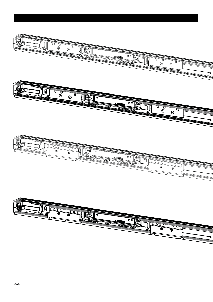
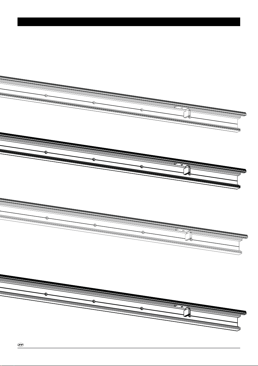
The automatic Linear Polaris operator has been designed and developed:
* Only and exclusively for the automation of single sliding internal doors, and therefore it
cannot be used for purposes other than those described in this manual, in order to
ensure the safety and performance of the product, under all circumstances.
* Following all points described in Directive EN16005 “Automatic pedestrian doors, Safety
in use” and Directive EN16361 “Power operated pedestrian doors – Product standard,
performance characteristics”, paying special attention to the articles referred to
automatic sliding doors for internal use.
* For a correct performance, respecting a maximum weight of 80 Kg. per leaf.

INSTALLATION MANUAL / MI0216.1 www.jnf.pt 5/44
JNF declines all civil or criminal liabilities for injuries caused to persons, animals and/or objects as a
result of:
* Not proceeding following the indications contained in the installation, user and
maintenance manuals.
* A non-authorized manipulation of the product.
* The replacement of parts and/or pieces of the operator, as well as the use of accessories
which are not original, or which have not been homologated by the manufacturer.
* Removing, deleting or altering the stickers, labels and/or other indications placed in
origin, on the automatic door operator or its accessories.
* Standing within the course of the door leaf of the automatic door, or performing tasks
near possible parts in motion.
2.3. Recommendations
All Linear Polaris automatic operators are delivered with an identication sticker. For a proper
identication of the product in case of claims or inquiries, the data displayed on the sticker must be
communicated to the concerned person.
Before the installation starts, please check that the product described on the sticker attached to
the packaging corresponds to the material ordered, and with that described in the delivery note.
Verify that the product has suered no damage during transport.
To prevent possible condensation of water inside the packaging during the storage period,
we recommend to keep the product inside its original packaging, to not expose it outdoors, to keep it
away of sunlight, and to always store it in a dry environment.
2.4. Installation requirements
* The power cable that connects with the cable supplied must have a minimum section of
2,5 mm²
* For a good performance, the operator must be levelled in all 3 axis, and be rmly xed
to a solid vertical suface.
GENERAL SAFETY INSTRUCTION
90º
WALL SIDE VIEW WALL TOP VIEW DOOR WELL VIEW

INSTALLATION MANUAL / MI0216.1 www.jnf.pt 6/44
GENERAL SAFETY INSTRUCTION
2.5. List of tools required for installation
2.6. Warranty
The manufacturer’s warranty for the Linear Polaris automatic operator will be VOID if:
* The installation, use and/or maintenance of the product did not follow the norms,
instructions and indications described in this manual.
* Using non-original components, accessories, parts, pieces or electronics systems, being
these new or for replacement purpose, when these parts haven’t been supplied or
homologated by the supplier.
2.7. Diposal and recycling
When disposing the packaging materials, it is recommended to check the specic regulation in force
at the installation site, before proceeding to dispose it.
Packaging materials are similar to other urban solid waste materials, and therefore they can be
easily disposed aer doing a selective classication and recycling.
When the product needs to be disposed, as this is composed of dierent materials, we recommend:
* Materials such as aluminium, plastic, steel, electrical cables (etc) are solid waste
materials, which need to be carefully classied for a proper recycling in authorized
recycling centres.
* Other components such as the plates of electronic circuits, capacitors, batteries,
magnets (etc) may contain contaminating materials, and as such, they must be carefully
removed and delivered to companies specialized in their evacuation, classication and
disposal.
Do not throw away the packaging or product materials anywhere. Recycle!!
LEVEL
ALLEN KEY (Nº 4 & 5)
DRILLING MACHINE
SCREW DRIVER SCREW DRIVER
WRENCH (Nº 10 & 13)

INSTALLATION MANUAL / MI0216.1 www.jnf.pt 7/4 4
TECHNICAL DATA
TECHNICAL SPECIFICATIONS
01. Mechanical features
02. Electrical features
MAIN
FEATURES
POWER
SUPPLY
ADJUSTABLE
PARAMETERS
MOTOR
OTHER
FEATURES
POWER
CONSUMPTION
CONTROL
GUIDE DIMENSIONS
LEAF WEIGHT
Clear opening width (mm): 700-1400
Operator length (mm): 2000/3000
Opening speed: adjustable between 200 and 800mm/sec
Closing speed: 200mm/sec - EN16005 “Low Energy”
Guide weight: 8-10kg
230 V CA - 50/60 Hz
Current (operating / peak): 3A / 5A
Protection fuse: 5A
Cable section: 3x1,0mm2. Lenght 2m
Opening direction: right or le
“Low Energy” or Normal Mode
Opening speed
Closing force
Reopening sensitivity
Hold open time
Type: Linear LSMPM (Linear Synchronous Motor with Permanent Magnets)
Number of poles: 3
Pitch pole: 50mm
Number of phases: 3
Voltage: 24V DC
Permanent neodymium magnets
Force <100 N
60mm (height) x 70mm (width)
Min. 10kg / Max. 80kg
Operating noise <50dB
Use - Continuous
Number of cycles > 1.000.000
In motion: 80W
Max (0,2 sec): 150W
In stand-by: 5W
Motion control by means of a driver with eld oriented control (FOC)
Self-adjustment of clear opening
Wireless communication via Bluetooth
ACCESSORIES
OPERATING
TEMPERATURE
Voltage: 24V CC
Current: 1A
Min. 5ºC
Max. 40ºC

INSTALLATION MANUAL / MI0216.1 www.jnf.pt 8/44
TECHNICAL DATA
IN.15.712.D - FOR WOOD
IN.15.702.D - FOR GLASS
IN.15.702.D.EL - FOR GLASS WITH E- LOCK
IN.15.716.D.EL - FOR WOOD WITH E-LOCK

INSTALLATION MANUAL / MI0216.1 www.jnf.pt 9/44
TECHNICAL DATA

INSTALLATION MANUAL / MI0216.1 www.jnf.pt 10/44
TECHNICAL DATA
WHEELS (x2)
FLOOR GUIDE (x1)
UPPER TRACK (x1)
MOTOR (x1)
STOPPER (x2)
FRONT COVER (x1)
CURRENT TRANSFORMER (x1)
POWER CABLE (x1)
SIDE COVER (x2)
ELOCK (OPTIONAL)WOOD ADAPTER (OPTIONAL)

INSTALLATION MANUAL / MI0216.1 www.jnf.pt 11/44
INSTALLATION INSTRUCTION
2.VERIFY THE OPENING DIRECTION AND THE OPERATOR LENGTH
IN.15.702.D / IN.15.712.D
RIGHT SIDE OPENING (FROM THE SIDE OF THE OPERATOR)
IN.15.702.E / IN.15.712.E
LEFT SIDE OPENING (FROM THE SIDE OF THE OPERATOR)

INSTALLATION MANUAL / MI0216.1 www.jnf.pt 12/44
INSTALLATION INSTRUCTION
3.MOUNTING THE OPERATOR
3.1. Measure the opening width and height
Legend:
DL = Drive length
OW = Opening width (Wall passage)
CW = Clear width
SW = Width of Sliding leaf
D1/D2 = Overlap
D3 = Finger protection / Handle (Optional)
A1/A2 = Header extension (Optional)
With overlap
Without overlap
DL = 2 * CW + 50min + (A1 +A2)
CW = OW - D3
Door with = OW + D1 + D2
a
b
ow

INSTALLATION MANUAL / MI0216.1 www.jnf.pt 13/44
INSTALLATION INSTRUCTION
3.MOUNTING THE OPERATOR
3.2. Preparations before mounting
3.2.1. Drilling
200 d d d d d d d d d d
Ø6
D1+A1/A2
200 200
200
d=200 mm
Fixing to roof
(With optional corner)
Fixing to wall Fixing to iron beam Fixing to glass
c
abd
D1 = Leaf overlap
A1 = Header Extension

INSTALLATION MANUAL / MI0216.1 www.jnf.pt 14/44
INSTALLATION INSTRUCTION
3.MOUNTING THE OPERATOR
3.2.2. Cutting the track
If it’s needed to cut the track, the front cover and the guide must be also cutted. For that it’s
recomended to use a circular saw.

INSTALLATION MANUAL / MI0216.1 www.jnf.pt 15/44
INSTALLATION INSTRUCTION
No contact between
the side cover and
the guide
If needed, remove a piece of magnets.
Be sure that the guide and the
side cover don’t conctact
ATTENTION
The track must be cutted on the oposite side
of the current transformer

INSTALLATION MANUAL / MI0216.1 www.jnf.pt 16/44
INSTALLATION INSTRUCTION
3.MOUNTING THE OPERATOR
3.2.2. Door dimension - Glass
X - 40
X
30
Ø14
10
40
60
70
15 38
33
31
X - 40
X
10
40
60
70
33
30
X - 40
X
10
40
60
70
38
33
+2,5
-2,5
31
+2,5
-2,5
31
+2,5
-2,5
X - 40
X
30
Ø14
10
40
60
70
15
33
31
+2,5
-2,5
X - 40
X
30
Ø14
10
40
60
70
15 38
33
31
X - 40
X
10
40
60
70
33
30
X - 40
X
10
40
60
70
38
33
+2,5
-2,5
31
+2,5
-2,5
31
+2,5
-2,5
X - 40
X
30
Ø14
10
40
60
70
15
33
31
+2,5
-2,5

INSTALLATION MANUAL / MI0216.1 www.jnf.pt 17/4 4
INSTALLATION INSTRUCTION
3.MOUNTING THE OPERATOR
3.2.2. Door dimension - Wood
X - 80
10
47
70
32
11
X - 80
X
10
21
60
70
5
30
X
60
30
>30mm>30mm
X - 80
10
47
70
X
60
>30mm
38,5
29,5 35mm
27 40mm
30mm
22 50mm
32
29,5 35mm
27 40mm
30mm
22 50mm
30mm
35mm
40mm
50mm
X - 80
10
47
70
>30mm
38,5
32
29,5 35mm
27 40mm
30mm
22 50mm
X
30
Ø14
60
15
+2,5
-2,5 11+2,5
-2,5
11+2,5
-2,5 11+2,5
-2,5
X - 80
10
47
70
32
11
X - 80
X
10
21
60
70
5
30
X
60
30
>30mm>30mm
X - 80
10
47
70
X
60
>30mm
38,5
29,5 35mm
27 40mm
30mm
22 50mm
32
29,5 35mm
27 40mm
30mm
22 50mm
30mm
35mm
40mm
50mm
X - 80
10
47
70
>30mm
38,5
32
29,5 35mm
27 40mm
30mm
22 50mm
X
30
Ø14
60
15
+2,5
-2,5 11+2,5
-2,5
11+2,5
-2,5 11+2,5
-2,5
30mm
35mm
40mm
50mm
30mm
35mm
40mm
50mm
30mm
35mm
40mm
50mm
30mm
35mm
40mm
50mm

INSTALLATION MANUAL / MI0216.1 www.jnf.pt 18/44
INSTALLATION INSTRUCTION
3.MOUNTING THE OPERATOR
3.2.2. Glass Cutout (not E-LOCK)
A
28
190 50
150
140
R6
R6
3 3
R14
8
MIN. 950mm

INSTALLATION MANUAL / MI0216.1 www.jnf.pt 19/44
3.MOUNTING THE OPERATOR
3.3. Glass Cutout - E-LOCK
INSTALLATION INSTRUCTION
A
MIN. 1000mm
28
50
150
R6
R6
3 3
R14
8
180
230
28
50
150
R6
R6
3 3
R14
8
140
B
190
Example for Open Right cases
For Open Le, the dimensions must be inverted

INSTALLATION MANUAL / MI0216.1 www.jnf.pt 20/44
INSTALLATION INSTRUCTION
3.MOUNTING THE OPERATOR
3.4. Mounting instructions - GLASS
ATTENTION
Clean the glass with
degreasing agent
before mounting
Clean the track
aer mounting
Relieve the nut before
next to the motor
before mounting the
door.
Note:
Only tight again aer the
“Self Adjustment” (Page 34).
This manual suits for next models
3
Table of contents
Other JNF Door Opening System manuals