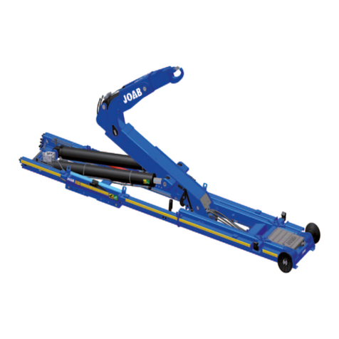
Joab Hookmaster User manual

JOAB Försäljnings AB
Östergärde Industriområde
SE-417 29 Gothenburg
Telephone
031-705 06 00
Fax:
031-705 06 09
E-mail:
info@joab.se
Operation and Maintenance
Manual for Hook-Lifts
Hookmaster
www.joab.se
13293 Edition 6 | 2021-02-22 | KM

Hookmaster manual: 13293 Edition 6 | 2021-02-22

iii
Contents
Introduction V
About The Hookmaster 1
Correct Usage 2
Main Components 3
Optional Locking Mechanisms 4
Manufacturer Plate 4
Design 4
Body Standard 7
Safety 9
Emergency Operation 10
Operation – Electrical Systems 11
CBW Controller 11
User Interface 12
Icons 12
Page Set-Ups 13
Function Buttons 14
Background Light 15
Warnings 15
Control Stick Functions 16
Continuous Hydraulic Supply 17
Emergency Stop 18
Operation – Air Systems 19
Cab Mounted Control Unit 19
LED Display And Buttons 20
Trailer Warning Lights 21
Emergency Stop 21
Radio Controllers 23
Before Operation 23
Operation – Electrical Systems 23
Display 24
LEDs 24
Emergency Stop 24
Function Mode 25
Start The Radio Controller 25
Axle Weight Reading 26
Charging 26
Hookmaster manual: 13293 Edition 6 | 2021-02-22

Operation – Air Systems 27
LEDs 27
Emergency Stop 27
Function Mode 27
Start The Radio Controller 28
Distributing A Load On A Body 29
Loading A Body 31
Tipping A Body 35
Shunting A Body 37
Unloading A Body 39
Service And Maintenance 41
Daily Maintenance 41
Washing The Hook-Lift 42
Lubrication Points 43
Service Of The Hook-Lift 44
Service-Reminder Sticker 44
Service Packets And Warranty 44
Working On The Hook-Lift 45
Safety Warnings 47
Technical Data 49
Fault Tracing The Hook-Lift 51
Contact Information 53
Service And Warranty 53
iv
Contents
Hookmaster manual: 13293 Edition 6 | 2021-02-22

v
Introduction
This manual covers the operation and maintenance of your Hookmaster. It contains important
information for your own safety and the surrounding environment.
JOAB’s products are characterised by a high level of safety, reliability, and long service-life. To
get the best out of your Hookmaster, we recommend reading this manual carefully
This manual also contains information regarding fault tracing, lubrication, and servicing of your
Hookmaster. This manual is based on the original mounted equipment only. Refer to the rel-
evant supplier’s manuals for all other optional or auxiliary equipment.
JOAB accepts no liability for the consequences that occur due to work carried out by non-pro-
fessionals. Do not make modifications to your Hookmaster, this can affect its structural integrity.
If a modification is necessary, seek advice from JOAB first.
When your Hookmaster is delivered, check that it is undamaged and functions correctly. If not,
contact JOAB, your dealer, or other supplier.
The technical data, designs and illustrations found in this manual are not binding. JOAB AB
retains the right to make changes without prior notice.
The general delivery regulations applyto all hook-lifts sold in Sweden.
For certain deliveries a CD with training material is provided. It is intended to give an overall
description of handling JOAB's products, such as hook-lifts, skip loaders, and Hookmaster.
Always bare in mind that it is the operator that is responsible for handling the Hookmaster.
© JOABAB
Hookmaster manual: 13293 Edition 6 | 2021-02-22

vi
Introduction |
Hookmaster manual: 13293 Edition 6 | 2021-02-22

1
About the Hookmaster
JOAB's hook-lifts are multipurpose. They can
be used with all vehicle manufacturers.
However, it is important that the vehicle has
been built specifically for the purpose of bear-
ing a hook-lift.
It is important to verify that the vehicle has the
correct axle distance and wheelbase.
JOAB’s Hookmaster is designed to transport
different types of bodies that have been man-
ufactured according to the Swedish standard
SS-3021.
Type examples are skip bodies, flat beds and
tanks, as illustrated.
Mounting the hook-lift onto a vehicle that has
not been specifically designed for the purpose
of carrying a hook-lift will increase the risk of an
abnormal load on the vehicle. This in turn can
lead to serious injury or damage.
Hookmaster manual: 13293 Edition 6 | 2021-02-22

Correct Usage
Incorrect use of JOAB's products can lead to material fatigue and cause excessive wear to the
hydraulics and its components. The service life of the product can be reduced and in the worst-
case lead to breakdown.
Do not drive the vehicle with the hook lift
extended. It must be fully retracted.
Do not use the Hookmaster for any
other purpose than its intended use.
Make sure to reverse straight towards the
body. Do not reverse at an angle.
Do not force the Hookmaster to lift in
excess of the given specifications.
If the body is stuck, observe caution!
The Hookmaster can easily be dam-
aged.
2
About the Hookmaster | Correct Usage
Hookmaster manual: 13293 Edition 6 | 2021-02-22

Main Components
The Hookmaster consists of a sledge, tip-fame, hook-post, tip cylinder, and lifting-hook made of
high tensile steel. A auxiliary lifting cylinder is also used to facilitate tipping.
A. Hook post
B. Sledge
C. Tip frame
D. Hydraulic lock
E. Tip cylinder
F. Auxiliary cylinder
3
About the Hookmaster | Main Components
Hookmaster manual: 13293 Edition 6 | 2021-02-22

Optional Locking Mechanisms
If the Hookmaster is equipped with external
hydraulic locking devices, it is important that the
body has cut-outs, as shown. If not – the body
will be transported unsecured!
Manufacturer Plate
All hook-lifts have a manufacture-plate. The
information on the manufacture-plate must be
provided in the event of making a claim or when
ordering spare parts from JOAB.
The hook-lift's serial number is not just on the
manufacturer's plate, but is also stamped on
the cylinder cross-member, see image.
Design
JOAB's products are exposed to high stresses
and must therefore be very well thought out
and of very high quality. All JOAB's components
and designs undergo comprehensive testing.
We use computer simulation to find and elim-
inate weak points and to establish the load
capacity and service life of all components.
4
About the Hookmaster | Optional Locking Mechanisms
Hookmaster manual: 13293 Edition 6 | 2021-02-22

All development and design work and allman-
ufacturing is carried out by JOAB. We are ISO
9001 and ISO 14001 certified.
A large proportion of our production is auto-
mated. This ensures high quality in the man-
ufacturing process.
JOAB's paint facility meets all applicable envir-
onmental requirements.
5
About the Hookmaster | Design
Hookmaster manual: 13293 Edition 6 | 2021-02-22

6
About the Hookmaster | Design
Hookmaster manual: 13293 Edition 6 | 2021-02-22

7
Body Standard
The use of bodies that are not designed in accordance with the standard SS 3021
can lead to personal injury or environmental damage. JOAB accepts no responsibility
for the use of bodies that do not conform to the standard: SS 3021.
JOAB's hook-lifts are intended for handling bodies that meet the Swedish standard SS 3021.
The following are the most important requirements of the SS 3021.
Internal mechanical lock that locks the body
onto the hook-lift. This is optional equipment.
Cut-outs in the body's frame. These are used
to hydraulically lock the body onto the hook-lift.
Holes in the body's rear beam. These are used
to secure the body onto a trailer.
Modification in the body that allows the hook-lift
to lock the body onto the hook-lift with the use
of locking arms (optional).
The body must have a stop member that pre-
vents the body from moving forwards and into
the cab of the vehicle.
Internal holes located in the body's frame mem-
bers are used to lock the body onto a trailer.
Hookmaster manual: 13293 Edition 6 | 2021-02-22

8
Body Standard |
Hookmaster manual: 13293 Edition 6 | 2021-02-22

9
Safety
Observe all safety warnings. Failure to do so can lead to serious injury or damage to equipment.
For further information regarding warning labels placed on the vehicle, refer to "Safety Warn-
ings", on page 47.
All personnel operating the hook-lift must read and follow all warnings provided in this manual
and on the hook-lift.
Before the start of each working day the hook-
lift must be inspected to ensure that no foreign
objects are between the hook-lift's moving
parts.
Always make sure that the vehicle is on a level
and firm surface before operating the hook-lift.
Failure to do so can cause the vehicle to
become unevenly loaded and lead to it tipping
over.
If the vehicle leans two or more degrees there
is a risk that it will tip over.
Before collecting a body, make sure that its
body-bracket is undamaged.
Make sure that the hook on the hook-lift
engages the body's bracket properly, as shown
opposite. Always lock the safety hook.
Do not drive the vehicle with the Hookmaster
raised. There is a serious risk of colliding with
overhead electrical wiring or similar. In addi-
tion, there is a risk of toppling over.
Hookmaster manual: 13293 Edition 6 | 2021-02-22

Do not tip, load, or unload bodies when the
vehicle’s axles are raised.
Do not make any modifications to the hook-lift
as this can effect its structural properties. If a
modification is required, contact JOAB for
advice before making a modification to the
hook-lift.
Emergency Operation
NOTE! when using the emergency operating system, the hook-lift's safety system is
disengaged. Caution must be taken! When the safety system is disengaged it is pos-
sible to damage the hook-lift or cause injury. Before using the emergency override
make sure that you are fully aware of its operation.
In the event of a failure in the hook-lift’s control
system it is possible to operate the hook-lift via
the hydraulic block, as shown opposite. An
emergency operating lever is supplied with the
hook-lift for this purpose. This is normally
placed in the driver's door.
If in any doubt about the use of the emergency
override, contact JOAB for advice before using
it.
10
Safety | Emergency Operation
Hookmaster manual: 13293 Edition 6 | 2021-02-22

11
Operation – Electrical Systems
This chapter describes the operation of hook-lifts that are electrically controlled. For inform-
ation about pneumatically controlled hook-lifts, see "Operation – Air Systems", on page 19.
The hook-lift can be controlled by a cab mounted controller or a radio controller. Radio con-
trollers are an extra option. For further information see "Radio Controllers", on page 23.
Electrically controlled systems have a control panel with integrated control stick, called the CBW
control unit. In pneumatic systems, indication is via an LED display and the control stick is a sep-
arate unit. For more information about the CBW control unit, see below. For more information
about pneumatic systems, see "Operation – Air Systems", on page 19.
CBW Controller
The CBW controller has both a display and control
stick, as shown, and is used to control all functions of
the hook-lift.
Certain functions, such as the operation of the
hydraulic pump, can be installed on the cab instru-
ment panel, either in addition or separate from the
CBW controller, as required.
The CBW control unit has the following main com-
ponents.
1. Emergency Stop
2. User Interface
3. Control stick
4. Mounting bracket
5. Screen lock screw
The emergencystop button isused in case of an emergency. Once pressed, all functions of the
hook-lift that could cause injury are disabled. To restore operation the system must be restar-
ted.
The user interface of the CBW controller has a 2.8 inch colour display. It is configurable. It is pos-
sible to display one of five different page set-ups. Each page set-up can have six user defined
functions, such as turning lights on. For further information see "Page Set-Ups", on page 13.
The control stick is used to control the basic functions of the hook-lift, such as tipping. For
detailed information regarding its function, refer to "Control Stick Functions", on page 16.
Hookmaster manual: 13293 Edition 6 | 2021-02-22

The mounting bracket is used to mount the unit inside the cab. Normally it is mounted onto the
driver's A-post. However, it is also possible to mount it onto the driver's right arm rest. This is
ideal for snow ploughs.
User Interface
Shown opposite is an overview of the user inter-
face.
The areas marked with a white rectangle on the
screen are programmable. The user can set
which functions are placed there. These func-
tions are activated by pressing the cor-
responding buttons: F1–F4 and the UP/DOWN
arrows. For further information on how to set
these functions, refer to "Function Buttons", on
page 14 below.
The function icons (F1–F4 and the UP/DOWN
arrow buttons) that are displayed in the user
interface is dependent upon which page set-up
is selected. There are four different page set-
ups. To switch between these press either the left or right arrow button located below the
screen. For more information see "Page Set-Ups", on page 13.
All other icons that are displayed on the screen (not the user defined functions) simply provide
feedback to the user regarding the status of the hook-lift, which page set-up is active, and active
functions, such as lights on etc.
Icons
Provided below is a list of the functions available in the user interface and their meaning. Note,
not all functions listed below are activated for all installations. Some of the functions are optional
extras, these are marked with an asterisk (*).
Functions that can be selected for the programmable areas (F1–F4 and the UP and DOWN but-
tons) are coloured white. All other buttons (orange and green) simply provide feedback to the
user as to whether or not they are active.
Icon Function Icon Function
Night mode Spreader flap – VEHICLE*
Table 1: User interface – icon description
12
Operation – Electrical Systems | CBW controller
Hookmaster manual: 13293 Edition 6 | 2021-02-22

Icon Function Icon Function
Load light – ON Automatic flap – VEHICLE*
Reversing light – ON Tip trailer – UP*
Flashing light – ON Tip trailer – DOWN*
Red light – ON Draw bar*
Safety hook is OPEN* Hydraulic lock – LOCK
Hydraulic lock is OPEN Hydraulic lock – OPEN
Hydraulic pump (start/stop) Automatic flap – VEHICLE*
Skip loader – TRAILER* Continuous hydraulic supply
(start/stop)*
Axle lift – TRAILER* Axle lift – TRAILER*
Automatic flap – TRAILER* --
Table 1: User interface – icon description (continued)
* Option: Not standard equipment.
Page Set-Ups
The user interface can display four different page set-ups, with different user defined functions.
The page set-ups are described in Table 2 below. Which page set-up is shown is indicated in the
display's lower right hand corner with one of the icons below (see "User Interface", on page 12).
13
Operation – Electrical Systems | CBW controller
Hookmaster manual: 13293 Edition 6 | 2021-02-22

Icon Description Icon Description
Vehicle setup_1 Trailer setup
Vehicle setup_2 Lighting setup
Table 2: Page set-ups
To switch between these page set-ups, simply press either the left or right arrow button below
the display.
The number of page set-ups that are accessible via the left and right arrow buttons can be con-
figured as required (1–4 page set-ups). In the example shown below, three page set-ups are
selected, these are shown with a green rectangle below them. The three active page set-ups
will be visible when the left/right arrow buttons are pressed.
To configure which of the page set-ups are available when the left and right arrow buttons are
pressed, follow the procedure below:
1. Press and hold down the OK button and
press either the left or right arrow button
at the same time for a few seconds.
The screen will then display the menu
page options as shown.
2. Select the desired page set-up from those displayed and then press the OK button to either
activate it or deactivate it (active page set-ups have a green rectangle below them).
3. Pressand hold down the OK button for a few second to save the new settings.
Function Buttons
Each of the four page set-ups in the user interface can be configured with six personal functions.
The icons for the selected functions are placed at the bottom of the user interface (shown in
white rectangles, see "User Interface", on page 12). These functions are activated by pressing
the corresponding function buttons below the screen: F1–F4 and the UP/DOWN arrow but-
tons.
To set the desired function associated with the function buttons, follow the procedure below:
1. Press and hold the OK button while simultaneously pressing the function button that is to
be changed.
2. The current icon set for that function will be displayed with a green rectangle around it, as
shown below.
14
Operation – Electrical Systems | CBW controller
Hookmaster manual: 13293 Edition 6 | 2021-02-22
Table of contents
Other Joab Lifting System manuals