twin busch TW 250 Guide

TW 250
Base Plate Two Post Lift
Electrical Release
Lifting Capacity 5000 kg
Installation, Operation and Parts Manual
Read this entire manual carefully before installation or
operation of the lift. Follow the instructions strictly.

Twin Busch GmbH
2

Twin Busch GmbH
3
INDEX
1. Important safety instructions 4-5
1.1 Important notices
1.2 Qualified personnel
1.3 Danger notices
1.4 Training
1.5 Warning signs
2. Overview of the lift 6
2.1 General descriptions
2.2 Technical data
2.3 Construction of the lift
3. Installation instructions 7-8
3.1 Preparations before installation
3.1.1 Tools and equipments needed
3.1.2 A list for parts checking
3.1.3 Ground conditions
3.2 Precautions for installation
3.3 Installation
3.4 Items to be checked after installation
4. Operation instructions 8-9
4.1 Precautions
4.2 Flow chart for operation
4.3 Operation instructions
5. Trouble shooting 10
6. Maintenance 11
7. Annex 12-35
Annex1, Packing list of the whole lift
Annex2, Overall diagram
Annex3, Floor plan
Annex4, Hydraulic working system
Annex5, Wiring diagram
Annex6, Separated drawings for the lift
Annex7, Spare parts list

Twin Busch GmbH
4
IMPORTANT SAFETY INSTRUCTIONS
1.1 Important notices
Twin Busch offers a one-year's quality warranty for the whole machine, during which any quality problem will be properly solved to
the user's satisfaction. However, we will not take any responsibility for whatever bad consequence resulted from improper
installation and operation, overload running or unqualified ground condition.
This 2-posts lift is specially designed for lifting motor vehicles that weighs within its outmost lifting capacity. Users are not allowed to
use it for any other purposes. Otherwise, we, as well as our sales agency, will not bear any responsibility for accidents or damages of
the lift. Make sure to pay careful attention to the label of the lifting capacity attached on the lift and never try to lift cars with its
weight beyond.
Read this manual carefully before operating the machine so as to avoid economic loss or personnel casualty incurred by wrong
operation. Without professional advice, users are not permitted to make any modification to the control unit or whatever
mechanical unit.
1.2 Qualified personnel
1.2.1 Only qualified staff, who have been properly trained, can operate the lift.
1.2.2 The electrical connection must be done by a competent electrician.
1.2.3 People who are not concerned are not allowed in the lifting area.
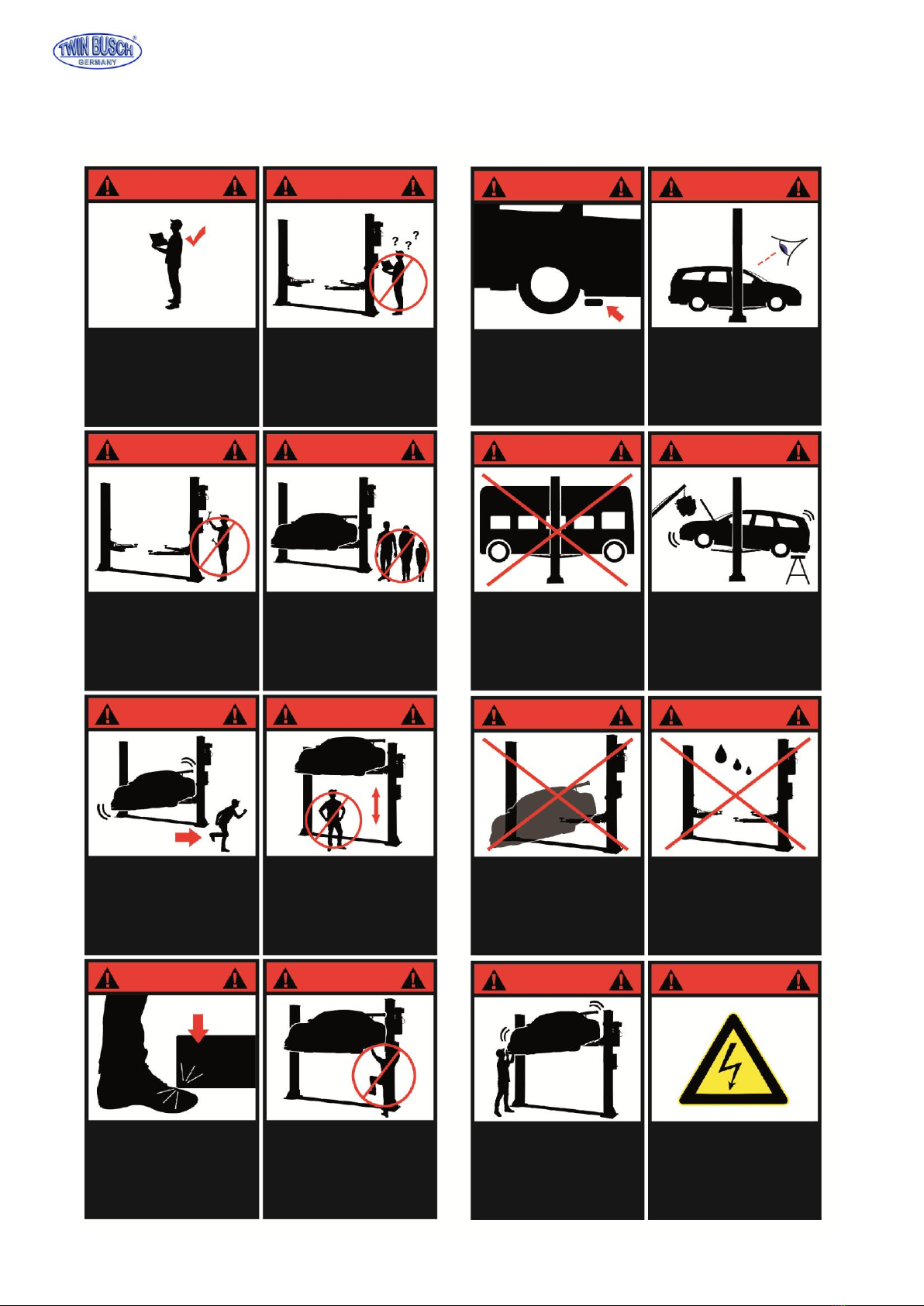
1.3 Danger notices
1.3.1 Do not install the lift on an asphalt surface.
1.3.2 Read and understand all safety warnings before operating the lift.
1.3.3 The lift, is not fit for outdoor use.
1.3.4 Keep hands and feet away from any moving parts. Keep feet clear of the lift when lowering.
1.3.5 Only qualified people that have been properly trained, can operate the lift.
1.3.6 Do not wear unfit clothes such as large clothes with flounces, tires, etc, which could be caught by moving parts of the lift.
1.3.7 To prevent evitable incidents, surrounding areas of the lift must be tidy and with nothing unconcerned.
1.3.8 The lift is simply designed to lift the entire body of vehicles, with its maximum weight within the lifting capacity.
1.3.9 Always insure the safety latches are engaged before any attempt to work near or under the vehicle.
1.3.10 Make sure to place the lifting pads to the positions as suggested by vehicle makers and when gradually lift the vehicle to the
desired height, operators should be certain that the vehicle will not slant, roll-over or slide in lifting process.
1.3.11 Check at any time the parts the lift to ensure the agility of moving parts and the performance of synchronization. Ensure
regular maintenance and if anything abnormal occurs, stop using the lift immediately and contact our dealers for help.
1.3.12 Lower the lift to its lowest position and do remember to cut off the power source when service finishes.
1.3.13 Do not modify any parts of the lift without manufacturer’s advice.
1.3.14 If the lift is going to left used for a long time, users are required to:
a. Disconnect the power source;
b. Empty the oil tank;
c. Lubricate the moving parts with hydraulic oil.
1.4 Training
Only qualified people, who have been properly trained, can operate the lift. We are quite willing to provide professional training for
the users when necessary.

Twin Busch GmbH
5
1.5 Warning signs
All safety warning signs attached on the machine are for the purpose of drawing the user’s attention to safety operation. The labels
must be kept clean and need to be replaced when they are worn-out or have dropped. Read the explanations of the labels carefully
and try to memorize them.
Please read the
instruction manual
and saftey warnings
before using!
Repairs and
maintenancem only by
qualied personnel, do
not tamper with lift
safety devices!
Always keep escape
routes free!
Always take care
of your feet
when lowering!
Use of the lift
by qualied
personnel only!
Only qualified
personnel are allowed
within the lift
working area!
No persons under
the lift (when lifting
or lowering)!
Never climb
on the lift!
Use only the vehicle
manufactures
recomended lifting
points!
Never exceed the
recomended lifting
capacity!
Never try to lift
using only
one side of the lift!
Avoid excessive
shaking of
the vehicle!
Check vehicle for
security
shortly after lifting!
Attention when
removing heavy
vehicle parts!
Protect the lift against
damp, especially the
electrical connections!
ATTENTION!
Danger of shock!
ATTENTION!
ATTENTION!
ATTENTION!
ATTENTION!
ATTENTION!
ATTENTION!
ATTENTION!
ATTENTION!
ATTENTION!
ATTENTION!
ATTENTION!
ATTENTION!
ATTENTION!
ATTENTION!
ATTENTION!
ATTENTION!

Twin Busch GmbH
6
OVERVIEW OF THE LIFT
2.1 General descriptions
This floor plate two posts lift is composed of posts, carriages, lifting arms, cylinders and motor unit, etc.
It is driven by an electro-hydraulic system. The gear pump delivers hydraulic oil to oil cylinders and pushes upwards its piston. The
piston drives the chain to raise the carriage and the lifting arms. During the lifting process,
the safety latch will automatically and firmly bite with the safety teeth block in the posts. Therefore, no slipping will occur in case the
hydraulic system malfunctions.
Safety structure
2.2 Technical data
Model
Lifting capacity
Lifting time
Lifting height
Height
Width
Width between posts
TW 250
5000kg
50 Sec
1900mm
2912mm
4028mm
3342mm
2.3 Construction of the lift

Twin Busch GmbH
7
INSTALLATION INSTRUCTIONS
3.1 Preparations before installation
3.1.1 Tools and equipment needed
Appropriate lifting equipment
Anti-abrasion hydraulic oil.
Rotary Hammer Drill with 3/4’’ drill bit.
Chalk and tape measure, magnetic plump, 8 metersФ15 level pipe.
Sockets and open wrenches, a set of inside hex wrenches, cross and straight screw drivers.
Hammer, 4pounds, sharp nose pliers, Ф17,Ф19,Ф22 socket spanners。
3.1.2 List for parts checking ---Annex 1(Packing list)
Unfold the package and check if any parts are missed as per Annex 1. Do not hesitate to contact us in case any parts missing
3.1.3 Ground conditions
The lift should be fixed on a smooth and solid concrete ground with its strength more than 3000psi, tolerance of flatness less than
5mm and minimum thickness of 200mm.
3.2 Precautions for installation
3.2.1 Make sure the two posts stand paralleled and are vertical to the ground. No slanting.
3.2.2 Joints of oil hose and steel cable must be firmly connected in order to avoid the looseness of steel cable and leakage
of oil hose.
3.2.3 All bolts should be firmly screwed up.
3.2.4 Do not place any vehicle on the lift in the case of trial running.
3.3 Installation
To make it easiler for you clients we have prepared a video that shows you how to perform the installation step by step.
This can be found on our internet site or on youtube.
3.4 Items to be checked after installation
S/N
Check items
YES
NO
1
Are the posts vertical to the floor?
2
Are the two posts paralleled?
3
Are oil hoses well connected?
4
Are steel cables well connected?
5
Are all lifting arms well fixed?
6
Are electrical connections right?
7
Are the rest joints firmly screwed?
8
Are all items need lubricating added with grease?

Twin Busch GmbH
8
Turn on the power switch
Press UP button
Motor drives the gear pump work
Cylinder piston drives the chain work
Chain drives the carriage rise
The lift is raised
Start
Start
Turn on the power switch
Press the DOWN button
The lift is lowered
OPERATION INSTRUCTIONS
4.1 Precautions
4.1.1 Check all the joints of oil hoses for leakage.
4.1.2 If a safety device malfunctions the lift shall not be used.
4.1.3 The machine shall not lift or lower an automobile if its center of gravity is not positioned midway of the swing arms.
4.1.4 Operators and other personnel concerned should stand in a safety area during lifting and lowering process.
4.1.5 When lifting arms rise to the desired height, switch off the power at once to prevent any mal-operation done by
unconcerned people.
4.1.6. Make sure the safety lock of the lift is engaged before you start working under the vehicle.
4.2 Flow chart for operation
Raising
Lowering

Twin Busch GmbH
9
4.3 Operation instructions
Raise the lift
1. Make sure that you have read and understood the operation manual before operation.
2. Park the vehicle between two posts.
3. Adjust the lifting arms until they reach the supporting positions of the vehicle and make sure the gravity of vehicle located in
the center of four lifting arms.
4. Connect the power supply and switch on.
5. Press the”UP”button on the control box until the pads of lifting arms touched the prop-position of vehicle.
6. Keep on raising the vehicle to let it have a bit clearance from the ground and check again its stability.
7. Raise the vehicle to the desired height, and turn off the power and then perform maintenance or repair work underneath.
Lower the lift
1. Switch on.
2. Press the “DOWN”button on the control box. Meanwhile the lifting arms automatically go upwards about 5CM which releases
the safety lock. The lift lowers.
3. After the lifting arms lower to the lowest position, pull them out from under the vehicle and clear up all the obstacles.
4. Drive the vehicle away.
Description
Function
Power Switch
Control power
Power indicator
Indicate if power being connected
UP button
Raise the lift
Safety lock button
Ensure safety in operation process
DOWN button
Lower the lift
Emergency stop
Ensure safety

Twin Busch GmbH
10
TROUBLE SHOOTING
ATTENTION: If the problem can not be fixed by yourself, please do not hesitate to contact us for help .We will offer our service at the
earliest time we can. By the way, troubles could be judged and solved much faster if more details or pictures could be provided.
TROUBLES
CAUSE
SOLUTION
Abnormal noise
Abrasion exists on insider surface of the posts.
Grease the inside of the post.
Trash in the post.
Clear the trash
Motor does not
run and will not rise
The wire connection is loose.
Check and make a good connection.
The motor is blown.
Replace it.
The limit switch is damaged or the wire connection is loose.
Connect it or adjust or replace the
limit switch.
Motor runs but
will not raise
The motor run reversely.
Check the wire connection.
Overflow valve is loose or jammed.
Clean or adjust it.
The gear pump is damaged.
Replace it.
Oil level is too low.
Add oil.
The oil hose became loose or dropped off.
Tighten it.
The cushion valve became loose or jammed.
Clean or adjusts it.
Carriages go down
slowly after being
raised
The oil hose leaks.
Check or replace it.
The oil cylinder is not tightened.
Replace the seal.
The single valve leaks.
Clean or replace it.
Solenoid valve fails to work well.
Clean or replace it.
Steel cable is loose or not with same tightness
Check and adjust the tightness.
Raising too slow
The oil filter is jammed.
Clean or replace it.
Oil level is too low.
Add oil.
The overflow valve is not adjusted to the right position.
Adjust it.
The hydraulic oil is too hot ( above 45°).
Change the oil.
The seal of the cylinder is abraded.
Replace the seal.
Inside surface of the posts is not well greased.
Add grease.
Lowering too slow
The throttle valve jammed.
Clean or replace.
The hydraulic oil is dirty.
Change the oil.
The anti-surge valve jammed.
Clean it.
The oil hose jammed.
Replace it.
The steel cable is
abraded
No grease when installation or out of lifetime
Replace it.

Twin Busch GmbH
11
MAINTENANCE
Easy and low cost routine maintenance can ensure the lift works normally and safely. The frequency of routine maintenance is
determined by working condition and frequency.
THE FOLLOWING PARTS NEED TO BE LUBRICATED
6.1 Daily Check
The user must perform a daily check. Daily check of safety lock system in very important –the discovery of device failure before
action could save time and prevent great loss, injury or casualty.
·Before operation, judge whether the safety locks are engaged.
· Check whether oil hoses are well connected and whether they leak or not.
· Check
the connections of chain and steel cable and check the power unit.
· Check whether the expansion bolts are firmly screwed.
· Check if arm lock works well or not.
6.2 Weekly Check
· C
heck the flexibility of moving parts.
·
Check the working conditions of safety parts.
·
Check the amount of oil left in the oil tank.
· Check whether expansion bolt s are firmly screwed.
6.3 Monthly Check
· Check whether the expansion bolts are firmly screwed.
·
Check the tightness of the hydraulic system and screw firm the joints if it leaks.
·
Check the lubrication and abrasion circumstance of axial pins, carriages, lifting arms and other related parts and replace in
time with new ones if they failed to work well.
· Check the lubrication and abrasion circumstance of steel cable.
6.4. Yearly Check
· Empty the oil tank and check the quality of hydraulic oil.
· Wash and clean the oil filter.
If users strictly follow the above maintenance requirements, the lift will keep in a good working condition and meanwhile
accidents could be avoided to a large extent.
S/N
Description
1
Upper wheel
2
Steel cable
3
Chain wheel
4
Chain
5
Sliding block
6
Pin
7
Arm block
8
Lifting arm
9
Tray
10
Down wheel

Twin Busch GmbH
12
ANNEX
Annex 1, Packing List
S/N
Material #
Name
Drawing#
Property
Qty
1
Power side post assembly
FL-8225E-A1
Assembly
1
2
Post assembly
FL-8225E-A2
Assembly
1
3
Carriage assembly
FL-8225E-A3
Assembly
2
4
Lifting arms
FL-8225E-A4
Assembly
4
6
Slot base plate assembly
FL-8225E-A9
Powder coating parts
1
7
Base cover plate
FL-8225E-A10
Powder coating parts
1
8
Power system
Assembly
9
Control box
Assembly
1
10
A package of electromagnet
Package
1
11
Power unit
Assembly
1
12
Top cap
FL-8225E-A1-B4
ABS
2
Parts in the carton
614013009
Feet protection fenders
FL-8224-A8-B3
Powder coating parts
4
612013001
Lifting trays
FL-8225E-A7-B41
Assembly
4
615013002B
Protection cloth
FL-8225E-A10
Assembly
2
624001065
Rubber oil hose L=3380mm
Assembly
1
612015005
Shafts
FL-8224-A12
zinc-plating parts
4
410040061
Safety locking plate
FL-8224E-A1-B2
45#
4
420040060
Electromagnet cover
FL-8224E-A1-B5
ABS
4
612004003
Height adapter
FL-8225E-A11
Welding assembly
4
410040071
Orientation block
FL-8224E-A1-B3
Q235A
4
410040023
Hose and line cover
FL-8224E-A1-B8
Q235A
6
410010051
Rod of protection cloth
FL-8224-A1-B13
Q235A
4
201102020
Hex head full swivel screw
M8*35
Standard parts
4
202111014
Inside hex sunken head screw
M12*20
Standard parts
2
202110004
Hex socket cylinder head screw
M8*12
Standard parts
8
202101021
Cross cap screw
M5*10
Standard parts
24
202101025
Cross cap screw
M5*23
Standard parts
12
202101027
Cross cap screw
M6*8
Standard parts
4
202101031
Cross cap screw
M6*16
Standard parts
4
202103021
Cross cap screw
M8*16
Standard parts
4
204101004
Class C flat washer
Φ6
Standard parts
8
204101006
Class C flat washer
Φ8
Standard parts
4
204201005
Spring washer
Φ8
Standard parts
4
203101004
Hex nut
M6
Standard parts
8
203101006
Hex nut
M8
Standard parts
4
204301013
Type B circlip
Φ38
Standard parts
4
201201008
Expansion bolt
M18*180
Standard parts
12

Twin Busch GmbH
13
Annex2, Overall diagram

Twin Busch GmbH
14
Annex3, Floor plan

Twin Busch GmbH
15
Annex 4, Hydraulic System
S/N
Name
Qty
1
Motor
1
2
Hydraulic block
1
3
Overflow valve
1
4
Removable plug
2
5
Cushion valve
1
6
Oil absorbing pipe
1
7
Oil filter
1
8
Throttle valve
1
9
Oil pipe tie-in
1
10
E-magnetic unloading valve
1
11
One-way valve
1
12
Gear pump
1
13
Plastic oil tank
1
14
Oil tank cover
1
15
Oil back pipe
1
1. Main cylinder
2. Assistant cylinder
3. E-magnetic unloading valve
4. Throttle valve
5. Motor
6. Coupling
7. Gear pump
8. Single-way valve
9. Overflow valve
10. Anti-surge valve
11. Cushion valve
12. Emergent unloading valve

Twin Busch GmbH
16
Annex5, Wiring diagram
Single phase

Twin Busch GmbH
17
Three phase

Twin Busch GmbH
18

Twin Busch GmbH
19

Twin Busch GmbH
20
This manual suits for next models
1
Table of contents
Other twin busch Lifting System manuals