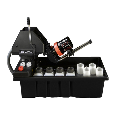
JOBO AutoLab ATL 2500 User manual

1
Wir stellen vor: Die JOBO ATL's 2200 / 2300 / 2400 / 2500
JOBO - das heißt über 60 Jahre Erfahrung in Papier- und Filmentwicklungstechnologie.
Die Autolabs ATL-2200/2300/2400/2500 sind die neusten freiprogrammierbaren, voll- automatischen Entwicklungsgeräte in
der JOBO ATL Palette. Bei der großen Vielfalt von verfügbaren Tanks und Trommeln ist das Autolab bestens für Arbeiten
verschiedensterGrößenordnungengeeignet.Daesvollkommenbedienerprogrammierbarist,könnenSieEntwicklungszeitenund
-temperaturen für verschiedene Prozesse einspeichern und innerhalb von wenigen Minuten entwicklungsbereit haben.
Alle für die fotografische Entwicklung notwendigen Funktionen, außer der Stabilisierung und Trocknung, sind beim ATL
vollautomatisch.
Die Temperaturregelung des Wassermantelbades arbeitet auf 1/10 Grad genau.
SowohldieFlaschenmitden zuverarbeitendenChemikalien alsauchdie rotierendeTrommelwerden durchdasWassermantelbad
auf Prozeßtemperatur gehalten.
Die Rotationsbewegung sowie der Drehrichtungswechsel werden durch den Mikroprocessor gesteuert. Temperierte Chemikalien
werden mittels eines Druckluftsystems von den
Vorratsbehältern in die Entwicklungstrommel gepumpt. Der eingebaute Computer zeigt, welche Menge an Chemikalien in den
Vorratsbehältern verblieben ist. Folglich läßt Ihr ATL das Starten eines Prozesses nicht zu, wenn nicht genügend Chemikalien
vorrätig sind. Der Mikroprocessor steuert ebenfalls den Zeitablauf jedes Entwicklungs- und Wässerungsschrittes. Außerdem
ermöglicht Ihnen das ATL die Rückgewinnung jeder verbrauchten Lösung, da sämtliche Chemikalien getrennt aufgefangen
werden. Die Rückgewinnung und Wiederaufbereitung verbrauchter Chemikalien macht die Entwicklung mit Ihrem ATL noch
wirtschaftlicher, bzw. ermöglicht eine umweltgerechte, preiswerte Entsorgung.
MERKMALE:
QUALITÄT
· Vollautomatisch durch Mikroprozessorsteuerung
· Konstante Ergebnisse von Prozeß zu Prozeß
· Jeder Prozeßschritt auf die Sekunde genau
WIRTSCHAFTLICHKEIT
· Gute Ausnutzung der Chemikalien
· Automatische Temperaturkontrolle des gesamten Systems
· Eingebaute Chemikalienauffangvorrichtung
VIELSEITIGKEIT
· Direktes Wechseln zwischen verschiedenen Prozessen
· Alle Prozesse sind möglich: z.B. C-41, E-6, Ciba/TM, S/W, R-3, RA-4, Litho, Röntgen
· Jedes Format: z.B. Rollfilm, Kleinbild, Planfilm von 6x9 bis 21x30 cm,
größere Formate auf Anfrage
· Papiergrößen von 7x10 bis 50x60
Wir fertigen Sonderanfertigungen nach Ihren Vorgaben für Filmformate bis 50x60cm, sowie Spiralen für Filmlängen bis 8
Meter und bis 127 mm Breite.
The JOBO ATL's 2200 / 2300 / 2400 / 2500
The AutoLabs ATL 2200/2300/2400 and 2500 are the newest user-programmable, fully automatic developing processors in the
JOBO product line. With the very many tanks and drums available, the Autolab is perfectly suited for a variety of processing
needs. The unit is completely user-programmable, enabling you to programme developing times and temperatures for different
processes, whereby the unit is ready for developing operations within a few minutes.
All functions needed for photographical development, except for stabilizing and drying, are fully automatic in the ATL. The
temperature control system of the water jacket reacts to deviations of 1/10th of a degree. The bottles with the solutions to be
processed as well as the rotating drum are kept at process temperature by the water jacket. The rotary movement is controlled by
the microprocessor. Pre-warmed solutions are pumped from the supply containers into the developing drum by means of a
compressedairsystem. Thebuilt-incomputershows how much solution is left in the storage containers. Consequently, your ATL
will not permit the starting of a process if there is not enough solution. The microprocessor also controls the timing of each
developingand rinsing step. Besides, the ATLpermits you the recovery ofeach used solution, because allchemicals are collected
separately. The recovery and reprocessing of used chemicals makes processing with your ATL even more profitable and permits
a non-polluting, economically priced waste disposal.
FEATURES:
QUALITY
·Fully automatic processing using a sophisticated microprocessor control system
· Consistent results run to run and day to day
· Each process step is accurate to the second
ECONOMIC EFFICIENCY
· Thorough use of chemicals
· Intelligently designed heating system to lower your electric bill
· Chemical recovery for silver reclamation
FLEXIBILITY
· Quickly and easily switch from one process to another
· All common processes are handled: e.g. C-41, E-6, Ciba/TM, B/W, Ilfochrome (Ciba), R 3, RA-4, lithographic, x-ray
· Any format: e.g. roll film, miniature film, sheet film from 6x9 to 21x30 cm, larger formats available on request
· Paper formats from 7x10 to 50x60
We are able to produce special units in accordance with your specifications for film formats up to 50x60 cm, and spirals for
film lengths up to 8 metres and up to 127 mm in width.

2
Hinweis =
Achtung =
2200
2200
= Attention, important to observe.
= Dangerofmechanicaldamageofthemachine!
= Danger of electrical schock!
= Closewatertapwhen not working with the processor
Additionalinformationregardinguse orfunctionality
Paycarefulattentiontothesecomments!
= Applies only to the indicated!
= Does not apply to the indicated!
= Sicherheit, unbedingt beachten!
= MechanischeBeschädigungderMaschinemöglich!
= Gefahr durch elektrischen Schlag!
= NachArbeitsendeWasserzuleitungschließen!
Wichtige Information für die Entwicklung oder die
Maschinenfunktion!
Unbedingt beachten, sonst Fehlfunktion!
= Gilt nur für dieses Modell!
= Gilt nicht für dieses Modell!
Warning =
2200
2200
Note =

3
KAPITEL SEITE
TECHNISCHE DATEN 6
1. AUSPACKEN 7
1.1 Entfernen des Kartons 7
1.2 Transportschäden 7
1.3 Verpackung 7
2. LIEFERUMFANG 8
3. INSTALLATIONSVORBEREITUNG 8
3.1 Standort 8
3.2 Stromversorgung 9
3.3 Wasserdruck 9
3.4 Wassertemperatur 10
3.5 Abwasser 10
3.6 Raumtemperatur 10
4. INSTALLATIONSANLEITUNG 11
4.1 Chemikalienauffangvorrichtung 11
4.2 Abwasseranschluß 11
4.3 Anschluß an das Trinkwassernetz 12
4.4 Anschluß der Nachfüllschläuche 12
4.5 Wasseranschluß 13
4.6 Elektrischer Anschluß 13
4.6.1 Notstromversorgung 14
4.7 Installationscheckliste 14
5. VORBEREITUNG ZUR INBETRIEBNAHME 15
5.1 Zu Beginn 15
5.2 Füllen des Wassermantelbades 15
5.3 Einstellung des temperierten Wasserzulaufes 15
5.4 Füllen der Chemikalienflaschen 16
5.5 Einstellen des Wasserspiegels 16
5.6 Tank System Anpassung 17
5.7 Rollenbockeinstellung 17
5.8 Automatische Kühlung 18
5.9 Auffangen gebrauchter Chemikalien 18
CHAPTER PAGE
TECHNICAL DATA 6
1. UNPACKING THE UNIT 7
1.1 Removing the packaging material and processor 7
1.2 Shipping damage 7
1.3 Keep the packaging material 7
2. SCOPE OF DELIVERY 8
3. PREPARING FOR INSTALLATION 8
3.1 Installation site 8
3.2 Electrical needs 9
3.3 Water pressure 9
3.4 Water temperature 10
3.5 Drain needs 10
3.6 Room temperature 10
4. INSTALLATION INSTRUCTIONS 11
4.1 Chemical reclamation 11
4.2 Drain connection 11
4.3 Connection to the drinking water supply 12
4.4 Connecting the refill lines 12
4.5 Connecting the rinse-water lines 13
4.6 Electrical connection 13
4.6.1 Battery back-up connection 14
4.7 Installation check list 14
5. PREPARINGTOPROCESS 15
5.1 First things first 15
5.2 Filling the water-bath 15
5.3 Setting the tempered water supply 15
5.4 Filling the chemical bottles 16
5.5 Filling the rear storage bottles 16
5.6 Setting the tank system plug 17
5.7 Setting the roller supports 17
5.8 Automatic cooling 18
5.9 Collecting used chemicals 18

4
CHAPTER PAGE
6. PROGRAMMING 20
6.1 General information about programming 20
6.1.1 SET mode 20
6.2 Programming 21
6.2.1 Altering process data 21
6.2.2 Raising and lowering the lift arm manually 22
6.2.3 Heat exchanger 22
6.2.4 Automatic refill 23
6.2.5 Rinsing option 23
6.2.6 Setting the rinse water temperature 24
6.2.7 Quick tempering feature 25
6.2.8 Option 25
6.2.9 Standby-Temp. 38°C 26
6.2.10 Changing the security code number 26
6.2.11 Setting the language 26
6.2.12 Adjusting the panel illumination 27
6.2.13 Cursor 27
6.2.14 Display of processing errors 27
6.2.15 Abort 27
7. STARTING A PROCESS 28
7.1 Selecting the correct process 28
7.2 Selecting the chemical volume needed 28
7.3 Selecting the rotation speed 29
7.4 Adjusting the remaining chemical volume 29
7.5 Final check list 30
7.6 Starting a process 30
7.7 At the end of a process 32
8. SPECIAL FUNCTIONS 32
8.1 Reading the Actual temperatures 32
8.2 Overriding the temperature check 33
8.3 Automatic Temperature Compensation (ATC) 34
8.3.1 DefiningATC 34
8.3.2 Mounting the B/W bottle rack 34
8.3.3 Selecting the program 34
8.3.3.1 Background temperature 34
8.3.4 Explanation of the ATC range 35
9. TROUBLESHOOTING 36
KAPITEL SEITE
6. PROGRAMMIERUNG 20
20
6.1 Wissenswertes zur Programmierung 20
6.1.1 Der SET-Mode 20
6.2 Die Programmierung 21
6.2.1 Prozeßdaten ändern 21
6.2.2 Hebearm manuell 22
6.2.3 Wärmetauscher 22
6.2.4 Automatische Nachfüllung 23
6.2.5 Wässerungs-Option 23
6.2.6 Einstellen der Waschwassertemperatur 24
6.2.7 Schnelltemperierung 25
6.2.8 Option 25
6.2.9 Standby-Temp. 38°C 26
6.2.10 Code-Nummer ändern 26
6.2.11 Sprache: *D* 26
6.2.12 LCD-Beleuchtung 27
6.2.13 Cursor 27
6.2.14 Fehlerliste 27
6.2.15 Abbrechen 27
7. STARTEN EINES PROZESSES 28
7.1 Wählen des Prozesses 28
7.2 Wahl der Fördermenge 28
7.3 Wahl der Rotationsgeschwindigkeit 29
7.4 Restmenge 29
7.5 Endgültige Checkliste 30
7.6 Starten des Prozesses 30
7.7 Nach Prozeßende 32
8. BESONDERE FUNKTIONEN 32
8.1 Ablesen der IST-Temperaturen 32
8.2 Überspringen der Temperaturkontrolle 33
8.3 ATC-Automatische Temperatur Compensation 34
8.3.1 Was ist ATC? 34
8.3.2 Mechanische Umbauten 34
8.3.3 Programm einstellen 34
8.3.3.1 Hintergrund-Temperatur 34
8.3.4 Arbeitsweise des Programms 35
9. STÖRUNGSSUCHE UND -BEHEBUNG 36

5
KAPITEL SEITE
10. BESONDERE VERARBEITUNGSHINWEISE 36
10.1 Einführung zur Entwicklung 36
10.2 E-6 Verarbeitung 36
10.3 S/W Verarbeitung 36
10.4 Werkseitige Belegung der Programme 37
11. REINIGUNG UND WARTUNG 40
11.1 Reinigung bei Prozeßwechsel 40
11.2 Reinigungsprogramme 40
11.3 Schmierung 40
11.4 Reinigung des Gerätes 41
11.5 Antriebsritzel 41
11.6 Verhinderung von Algenbildung 42
11.7 Entnehmen der Flaschen 42
11.8 Langzeit-Nichtbenutzung 42
11.9 Lagerung bei Minustemperaturen 42
11.10 Anmerkungen zu den Füllmengen 42
11.11 Reinigung des Luftfilters 42
12. SERVICE 43
12.1 Bevor Sie den Service kontakten 43
13. GARANTIE 44
14. LEGENDE 45
CHAPTER PAGE
10. SPECIAL PROCESSING INSTRUCTIONS 36
10.1 Introduction to the developing process 36
10.2 E-6 processing 36
10.3 B/W processing 36
10.4 Factory default settings 37
11. CLEANING AND MAINTENANCE 40
11.1 Clean-up at the end of the process 40
11.2 The Cleaning programmes 40
11.3 Lubrication of the lift arm 40
11.4 Cleaning the processor 41
11.5 Drive gears 41
11.6 Algae prevention 42
11.7 Removing the bottles 42
11.8 Prolonged periods of inoperation 42
11.9 Storing the processor below freezing 42
11.10 A note on the filling levels 42
11.11 Cleaning of the air filter 42
12. AFTER-SALES SERVICE 43
12.1 Before contacting the after-sales service 43
13. WARRANTY 44
14. LEGEND 45

6
TECHNISCHE DATEN
ATL-2400 / 2500 ATL-2200 / 2300
Höhe 122 cm (48") 61 cm (24")
Höhe mit größter
Trommel in Entleerstellung 177 cm (69") 116 cm (45")
Tiefe 51 cm (20") 51 cm (20")
Breite 117 cm (46") 117 cm (46")
Gewicht (leer) 100 kg (223 lbs) 35 kg (78 lbs)
Min. Wasserdruck 1 bar 1 bar (15 p.s.i.)
Max. Wasserdruck 6 bar 6 bar (90 p.s.i.)
Wassermantelbadkapazität ca. 16 L (4¼ ga) 16 L (4¼ ga)
Prozeß-Temperaturbereich 20 - 40°C (48,8 - 97,6°F)
Umgebungs-Temperaturbereich 15 - 28°C (36,6 - 68,3°F)
Leistung (alle Angaben in KW):
230 V 50/60 Hz 115 V 50/60 Hz
ATL-2200 1,3 0,9
ATL-2300 1,3 0,9
ATL-2400 1,3 0,9
ATL-2500 1,3 0,9
Spannungstoleranz: 230 V ± 10 %
115 V ± 10 %
TECHNICALDATA
ATL-2400 / 2500 ATL-2200 / 2300
Height 122 cm (48") 61 cm (24")
Height with largest
drum in drainage position 177 cm (69") 116 cm (45")
Depth 51 cm (20") 51 cm (20")
Width 117 cm (46") 117 cm (46")
Weight (empty) 100 kg (223 lbs) 35 kg (78 lbs)
Min. water pressure 1 bar 1 bar (15 p.s.i.)
Max. water pressure 6 bar 6 bar (90 p.s.i.)
Approx. capacity of water-jacket 16 L (4¼ ga) 16 L (4¼ ga)
Range of process temperature 20 - 40°C (28,8 - 97,6°F)
Allowable range of temperature in working area: 15 - 28°C (36,6 - 68,3°F)
Power ratings (in kW):
230 V 50/60 Hz 115 V 50/60 Hz
ATL-2200 1,3 0,9
ATL-2300 1,3 0,9
ATL-2400 1,3 0,9
ATL-2500 1,3 0,9
Voltage tolerance: 230 V ± 10 %
115 V ± 10 %

7
1. AUSPACKEN
1.1 Entfernen des Kartons
Das Gerät wird in einem Karton geliefert (Gesamtgewicht ca. 40 kg) (89 lbs). Zum Auspacken des ATL sind
2 Personen erforderlich. Sie schneiden das obere Klebeband durch und klappen den Karton auf. Entfernen Sie
die obere Stütze aus Wellkarton und die Schaumstoffpolster (siehe Zeichnung unten). Heben Sie, mit je
einer Person an den Enden des Kartons, den Processor vorsichtig aus dem Karton heraus.
1.2 Transportschäden
Prüfen Sie das Gerät auf etwaige Schäden und benachrichtigen Sie gegebenenfalls, umgehend die Spedition,
die das Gerät geliefert hat oder den Händler, von dem Sie das Gerät bezogen haben.
1.3 Verpackung
Um einen sicheren Transport bei eventuellen Servicereparaturen zu gewährleisten, verwenden Sie bitte nur
den Originalkarton mit den Einlagen und verpacken Sie das Gerät gemäß obenstehender Abbildungen. Für
Schäden, die durch unsachgemäße Verpackung entstehen, kann keine Haftung übernommen werden.
1. UNPACKING THE UNIT
1.1 Removingthepackagingmaterialandprocessor
The unit is delivered in a cardboard box (total weight approx. 37 kgs/82 lbs) with additional packaging.
To make unpacking and installation easier, it's necessary to have someone help. Cut the tape on the top of
the box and open it. Remove the upper support of corrugated cardboard and the styrofoam packaging (see
drawing below). With 1 person at each end of the box, carefully lift the processor out.
1.2 Shippingdamage
Make sure to check for any concealed shipping damage at this point. In the event your processor has
suffered any damage, contact the freight company or your local dealer immediately. It is important to file
any such claims immediately.
1.3 Keepthepackagingmaterial
Do not throw out the packaging materials. To ensure safe transportation for any repairs by our service
department which may be necessary, please use only the original box with the inserts and pack the unit as shown
in the illustrations above. We accept no responsibility for any damage which may occur as a result of incorrect
packing.

8
maximum height
mainslead
length:
200 cm
117 cm
51 cm
10 cm
61 cm
wall
116 cm
2. LIEFERUMFANG
Artikelbezeichnung Artikel Nr. Menge
ATL 2200 2300 2400 2500
Skalenflasche weiß ohne Deckel 05013 6 6 6 6
Skalenflasche weiß 3373 6 - - -
Processor-Clean 4181 1 1 1 1
Zubehörpaket 93024 1 1 1 1
Abflußgarnitur 92314 1 1 1 1
Kanisterwagen 95564 - - 1 1
Gestell 95563 - - 1 1
Netzkabel je nach Land 1 1 1 1
Bedienungsanleitung je nach Land 1 1 1 1
15 Liter Kanister mit Deckel und 3387 - - 6 6
Schwimmdeckel
15 Liter Kanister ohne Deckel und - - 6 6
Schwimmdeckel
Durchlaufflasche schwarz ø 7,5 05091 - - 6 6
3. INSTALLATIONSVORBEREITUNG
3.1 Standort
DasATLmußnichtineinerDunkelkammerinstalliertwerden,daalleJOBOTanksundTrommelnlichtdichtsind.
Das ATL sollte in der Nähe einer ausreichenden Abwassereinrichtung, Kaltwasseranschluß und ggf.
Warmwasseranschluß sowie einesStromanschlußes installiert werden.
Das ATL sollte auf einer ebenen Stellfläche mit einer Tragfähigkeit von mindestens 68 kg (150 lbs) installiert
werden. Die Stellfläche sollte wasserfest sein. Ebenfalls muß sie höher liegen, als die Abwassereinrichtung für
den Processor.
maximaleHöhe
Netzkabel
Länge:
200 cm
117 cm
51 cm
10 cm
61 cm
Mauer
116 cm
2200/2300
2. SCOPEOFDELIVERY
Article name Item No. Quantity
ATL 2200 2300 2400 2500
Scaled bottle, white without lid 05013 6 6 6 6
Scaled bottle, white 3373 6 - - -
Processor-Clean 4181 1 1 1 1
Accessory Kit 93024 1 1 1 1
Drainage Kit 92314 1 1 1 1
Chemical Reclamation Cart 95564 - - 1 1
Bench support 95563 - - 1 1
Mains cable according to country 1 1 1 1
Operating instruction according to country 1 1 1 1
15-litre canisters with lid and 3387 - - 6 6
floating lid
15-litre canisters without lid and - - 6 6
floating lid
Bottle with hole, black ø 7,5 05091 - - 6 6
3. PREPARING FOR INSTALLATION
3.1 Installation site
It is not necessary to install the ATL in a darkroom, it was designed for daylight operation. All JOBO tanks
and drums are light-tight when used properly.
The ATL should be installed near a suitable drain, a cold water source (and hot water source if required,) and an
appropriate power source.
The ATL should be installed on a level base with a load bearing capacity of at least 68 kg (150 lbs). The surface
should be water-proof. Also, it must be higher than the drain water installation for the processor.
2200/2300

9
Das ATL sollte auf einer ebenen und waagerechten Stellfläche mit einer Tragfähigkeit von mindestens 250 kg
pro m² installiert werden, dies verhindert Entwicklungsfehler durch ungleichmäßige Benetzung.
Die Stellfläche bzw. der Fußboden sollte wasserfest sein. Unebenheiten können ggf. durch die höhenverstell-
baren Füße ausgeglichen werden. Drehen Sie dazu mit dem im Beipack befindlichen Maulschlüssel die Stellfüße
auf die erforderliche Position, damit das ATL in der Waage steht.
3.2 Stromversorgung
Es wird ein geerdeter Stromanschluß benötigt. Nehmen Sie am besten Verbindung mit einem Elektriker vor
Ort auf. Achten Sie darauf, daß das Gerät nur an eine Steckdose mit Schutzkontakt angeschlossen werden
darf. Das Zwischenschalten eines FI-Schalters wird dringend empfohlen. Die Länge des Stromanschlußkabels
beträgt ungefähr 2,00 m. Stellen Sie sicher, daß sich eine ausreichend abgesicherte Steckdose innerhalb von
1,80m (6 ft.) vom Standort Ihres ATL's befindet.BeiderVerwendungeinesVerlängerungskabels muß dieses mit
einem Querschnitt von min. 1,5 mm² ausgelegt sein.
Beachten Sie die Angaben auf dem Typenschild des ATL's.
3.3 Wasserdruck
EinWasserdruckzwischen1 und 6 bar (15 und 90 p.s.i.) ist notwendig,um denProcessorzubetreiben.Ein Druck
von weniger als 1 bar kann eine ungewöhnlich lange Einfüllzeit für das Wassermantelbad oder ungenügende
Wässerungen zur Folge haben Wasserdruck von mehr als 6 bar kann Schaden am Processor verursachen. Bei
einem Wasserdruck über 6 bar empfehlen wir, den Druckminderer Art. Nr. 4177 vorzuschalten.
Warnung: Um die Möglichkeit von Wasserschäden durch undichte
Schläuche zu vermeiden, sollten sich die Wasserhähne in
Reichweite befinden. Diese stets schließen, wenn der
Prozessor nicht in Gebrauch ist!
2400/25002400/2500
The ATL should be installed on a level base with a load bearing capacity of at least 250 kg per m² . Failure to
do so will cause processing problems due to uneven wetting of the film or paper. The surface , or the floor, should
be waterproof. uneven surfaces can be compensated using the leveling feet. For this purpose, use the enclosed
spanner to turn the leveling feet to the required position so that the ATL is level.
3.2 Electricalneeds
An earthed mains connection point is required. It is recommendable to consult a local electrician. Please note that
the unit may only be connected to a socket equipped with an earthing contact. We strongly recommend to insert
a GFCI outlet. The length of the mains lead is approximately 1,80 m (6'). Ensure that an adequately fused circuit
is located within 1,80 m (6') of the installation point for your ATL. When using an extension lead, observe that
this has to have at least a diametre of 1,5 mm².
Note the information on the nameplate of the ATL.
3.3 Water pressure
A water pressure of between 1 and 6 bar (15 and 90 p.s.i.) is required in order to operate the processor.
A pressure level of less than 1 bar may result in unusually long filling times and insufficient rinsing.
Pressure greater than 6 bar may damage the processor. When water pressure above 6 bar pply, we recommend
installing the pressure reducer, (Item no. 4177), up-line.
Warning: To avoid the possibility of damage caused by water from leaking
tubes,the water tapsshould bereadily accessibleand turnedoff when
the processor is not being used!

10
3.4 Wassertemperatur
Das ATL benötigt je einen Kalt- und einen Warmwasseranschluß. Der temperierte Wasseranschluß sollte
genau auf die Entwicklungstemperatur eingestellt werden. Wenn keine temperierte Wasserversorgung zur
Verfügung steht, empfehlen wir den Warmwasserdruckspeicher mit Spezialmischbatterie Art. Nr. 4167.
Der Kaltwasseranschluß dient zur Füllung des Wassermantelbades und gleichzeitig zur Kühlung des ATL's.
Falls Prozesse gefahren werden, die unter der Umgebungstemperatur des Raumes liegen (z.B. 20°C für S/W),
so muß die Temperatur des zugeführten Wassers niedriger sein als die niedrigste Entwicklungstemperatur des
Prozesses. Falls die Temperatur des zugeführten Wassers zu hoch ist, kann das Wasser mit einer externen
Kühlvorrichtung gekühlt werden. Fragen Sie Ihren Fotohändler oder JOBO nach weiteren Informationen.
3.5 Abwasser
Das ATL hat zwei separate Abflußöffnungen; einen Wassermantelbadabfluß und einen gemeinsamen
Wasserablaßanschluß für Wässerung und Überlauf des Wassermantelbades.
(Siehe Illustration in Abschnitt 4.2)
Das ATL-2200/2300 kann auf einer Platte oder auf den besonders dafür entworfenen Arbeitstisch von JOBO
(Art. Nr. 4221) gestellt werden. In jedem Fall müssen beide Ablaßanschlüsse an eine Abwassereinrichtung
angeschlossen werden, die tiefer als der Processor liegt. Dazu benutzen Sie bitte die im Lieferumfang
enthaltenen Schläuche.
3.6 Raumtemperatur
Da der Processor ständig die Temperaturen des Wassermantelbades innerhalb der zugelassenen Grenze
konstant hält, wird eine normale Schwankung der Raumtemperatur von 15-28°C die exakte Temperierung
nicht beeinflussen. Es wird trotzdem empfohlen, den Processor nicht in der unmittelbaren Nähe von
Klimaanlagen oder Heizkörpern zu installieren.
Für eine gute Temperierung die hintere Flaschenabdeckung stets schließen.
3.4 Watertemperature
The newATL requires one cold and one warm water hook up each. The tempered water supply should be set
exactly to the developing temperature. If there is no warm water supply, we recommend the warm water
pressure tank with special mixing tap (Item no. 4167). The cold water connection serves for filling the water-
jacket and at the same time for cooling the ATL.
If processes are run that are below the ambient room temperature (e.g. 20°C for B/W), the temperature of the
supplied water must be lower than the lowest developing temperature of the process. If the temperature of the
supplied water is too high, the water can be cooled using an external cooling device. Ask your photo dealer or
JOBO for further information.
3.5 Drainneeds
The ATL has two separate drains; one for the water jacket another for the chemical reclamation area.
(see illustration in Section 4.2)
The ATL 2200/2300 can be installed on a plate or on the specially designed support table from JOBO
(Item no. 4221). In each case both outlets must be connected to a drain water installation, which is lower than
the processor. For this purpose please use the hoses included in the scope of supply.
3.6 Room temperature
As the processor continuously maintains the temperatures of the water-jacket bath within the permitted limit,
normal fluctuations in the room between 15-28°C (59-83°F) will have no effect on exact tempering of the water.
Even so, JOBO recommends that the processor is not installed directly in the path of a heating or air-
conditioning vent.
In order to secure a perfect process temperature, always keep the rear bottles covered.

11
4. INSTALLATION INSTRUCTIONS
4.1 Chemicalreclamation
The ATL collects used chemicals in bottles or 15-litre canisters.
4.2 Drainconnection
On the back of the ATL, there are two drain connections, the water bath (A) on the left and the chemical
collection/rinse (B) on the right (connections are illustrated below).
If the ATL is placed on a plate, both drain water outlets must be led to a suitable drain with hoses. To install
the hoses (1/2" PVC hose = water bath, 1" hose = reclamation area drain) push one end of the thinner hose on
connector A, then push the thicker hose onto connector B. Both hoses can then be joined to the connecting
element.
ATL 2200/2300
Bench support
(Item No. 4221)
for ATL 2200/
2300
Option
Chemical
reclamation cart
(Item No. 4225)
for ATL 2200/2300
Option
ATL 2400/
2500
A
B
ATL 2200/2300
Arbeitstisch
(Art. Nr. 4221)
für ATL 2200/
2300
Option
Chemikalienauf-
fangwagen
(Art. Nr. 4225)
für ATL 2200/2300
Option
ATL 2400/
2500
4. INSTALLATIONSANLEITUNG
4.1 Chemikalienauffangvorrichtung
Das ATL fängt die verbrauchten Chemikalien in Flaschen oder 15 Liter Kanistern auf.
4.2 Abwasseranschluß
An der Rückseite des ATL's befinden sich zwei Abwasseranschlüsse.
Der Hauptwannenabfluß (A) auf der linken Seite und der Überlauf/- Wässerungswasseranschluß (B) auf der
rechten Seite. (Siehe untenstehende Zeichnung.)
Falls das ATL auf eine Platte gestellt wird, müssen beide Abwasseranschlüsse mit Schläuchen in einen dafür
geeignetten Abfluß geleitet werden. Zum Installieren der Schläuche (1/2" PVC Schlauch = Hauptwannenan-
schluß, 1" Schlauch = Überlaufanschluß) schieben Sie ein Ende des dünneren Schlauches über den Anschluß A.
Schieben Sie den dickeren Schlauch über den Anschluß B. Beide Schläuche können mit dem Verbindungsstück
verbunden werden.
A
B

12
4.3 Connectiontothedrinkingwatersupply
In order to meet these regulations, the ATL’s must have an overflow system to prevent the water level in the
machine from rising above a certain level in the case of a blocked drain line. In a case where a drain line was
blocked, water could escape from this overflow point.
To insure proper operation of the processor, do not use demineralized or deionized water.
4.4 Connecting the refill lines
The refill hoses (models 2400/2500 only) need to be inserted in the 15-liter bottles stored below the processor.
The hard-plastic end goes into the hold on the top of the bottle.
Itisimportanttowatchthecorrectnumberingofthehoses.Theirnumbersmustcorrolatewiththeposition
numbers of the 15-litre canisters otherwise faulty developments will occur.
4.3 Anschluß an das Trinkwassernetz
Zur Einhaltung der Vorschriften ist an der Geräterückseite ein Überlauf angebracht, der bei verstopftem
Abfluß den maximalen Wasserspiegel im Gerät begrenzt. Bei verstopftem Abfluß könnte hier also Wasser
austreten!
Keindestilliertes oder entmineralisiertes wasser verwenden.
4.4 Anschluß der Nachfüllschläuche
Bei den Geräten ATL 2400 und ATL 2500 werden die Nachfüllschläuche mit der Lanze in die Kanister gesteckt.
Unbedingt auf die richtige Nummerierung achten, da es sonst zu Fehlentwicklungen kommen kann.
Lanze
2400/2500
2400/2500
End piece

13
Name plate
Main circuit connection
Fuse T 6,3A (230V) / T 10A (115V)
Internal supply heating element
Internal supply monitoring
If desired, a back-up system can be integrated.
4.5 Wasseranschluß
Das ATL benötigt zwei Wasseranschlüsse mit 3/4" Standard Gewinde. Wenn Sie auf die Rückseite des
Gerätes sehen, wird der mit einem roten Punkt gekennzeichnete Anschluß, mit dem temperierten
Warmwasseranschluß, der mit einem blauen Punkt gekennzeichnete Anschluß mit dem Kaltwasseranschluß
verbunden. Stellen Sie den temperierten Warmwasseranschluß auf die Entwicklungstemperatur ein.
Werden die Verbindungsschläuche angeschlossen, so achten Sie bitte darauf, daß die entilgewinde
einwandfrei sind. Drehen Sie die Muttern fest an, aber überdrehen Sie die Verbindung nicht, da sonst die
Gewinde beschädigt werden können. Der Druck der Wasserzufuhr muß zwischen 1 bis 6 bar liegen.
Wasserdruck unter 1 bar kann ungenügende Wässerung zur Folge haben und Wasserdruck über 6 bar kann
das ATL beschädigen. Falls notwendig, verwenden Sie einen Druckminderer (Art. Nr. 4177).
Hinweis: Bei partikelhaltigem Wasser empfehlen wir die Installation
eines Wasserfilters Art. Nr. 8050, um eine Beschädigung und
Rückstände auf den Filmen zu vermeiden.
4.6 Elektrischer Anschluß
Ein geerdeter, genügend abgesicherter Stromanschluß ist erforderlich. Beachten Sie die technischen Daten zu
Beginn dieser Bedienungsanleitung.
Wichtige Sicherheitshinweise
Warnung: Um ein unnötiges Risiko von Feuer, elektrischem Schock oder
persönlicher Verletzung zu verhindern, müssen der elektrische
Anschluß und die Erdung ordnungsgemäß installiert werden.
EsistdiepersönlicheVerantwortungdesProcessor-Eigentümers,
für ausreichende Sicherheit der Stromzufuhr zu sorgen. Ihr
Processor muß an eine ordnungsgemäße Erdung angeschlossen
werden, um im Fall einer Betriebsstörung oder eines Geräte-
defektes das Risiko eines elektrischen Schlages zu reduzieren.
Darüber hinaus empfehlen wir dringend die Verwendung eines
Fehlerstrom-Schutzschalters(FI-Schalter).
Der Processor ist mit einem Anschlußkabel ausgerüstet, das einen Schutzleiter und einen Stecker mit Schutz-
kontakt besitzt. Stecken Sie den Netzstecker in eine Steckdose, die ordnungsgemäß installiert und geerdet ist.
Verändern Sie unter keinen Umständen den Stecker des Netzkabels. Wenn der mitgelieferte Netzstecker nicht
in die Steckdose paßt, lassen Sie eine geeignete von einem autorisierten Elektriker installieren.
UmKondensatbildung in der Elektronikzu vermeiden, läuft derLüfter nach dem Ausschaltendrei Stunden nach.
Typenschild
Netzanschluß mit passender Kaltgeräte-Anschlußleitung
Sicherung T 6,3A (230V) / T 10A (115V)
interne Versorgung Heizung
interne Versorgung Steuerung
Hier kann gegebenenfalls ein Back-Up-System eingeschleift werden.
4.5 Connectingtherinsewaterlines
The ATL requires two rinse water connections with 3/4" standard thread.
When you look at the rear panel of the unit, you will see the connection point indicated with a red dot, which
is connected to the tempered hot water supply, and the connection point indicated with a blue dot, which is
connected to the cold water supply.
Set the tempered water supply to the developing temperature.
When connecting the supply tubes, please ensure that the valve threads are in perfect condition. Screw the nuts
tight,butdonotstripthethread,asthismaycausedamagetothethread.Thewatersupplypressuremustbebetween
1and6.Waterpressuresbelow1barmayresultininadequatewashing,andwaterpressuresover6barmaydamage
the ATL. If necessary, use a pressure reducer (Item no. 4177).
Note: When using water which contains particle matter, we recommend installation of a water filter
Item Mo. 8050, in order to prevent damage and deposits on the film.
4.6 Electrical connection
An earthed, adequately fused electric power supply is required. Please note the technical data at the beginning
of these operating instructions.
Important safety information
Warning: The electrical connection and the earthing must be installed in the
correct manner, in order to avoid any unnecessary risk of fire, electric
shock, or personal injury. The owner of the processor assumes full
responsibility for ensuring the electrical connection is sufficiently safe.
Your processor must be connected to a properly functioning earthing
system, in order to reduce the risk of electric shock in the event of a
malfunction or defect. In addition, we strongly recommend to connect
the processor to a GFCI (ground fault interrupter circuit).
The processor is equipped with a mains lead incorporating a protective conductor and a plug with an earthing
contact. Insert the mains plug in a socket which has been duly installed and earthed.
Under no circumstances is the plug of the mains lead to be changed. If the suppliedmains plug does not fit
into the socket, an authorised electrician is to be called in to install a suitable socket.
In order to prevent condensation in the electronics, the fan will operate for 3 hours after turning off the processor.

14
4.6.1 Notstromversorgung
IhrATL ist serienmäßigfürden Anschluß einerNotstromversorgung(Batterie-Back-Up)vorbereitet. Für weitere
Informationen wenden Sie sich bitte an JOBO-Labortechnik oder bestellen Sie das Batterie-Back-Up unter der
Art. Nr. 4267 (230 V) / Art. Nr. 4268 (115 V).
4.7 Installations Checkliste
·Der Processor ist mit der Wasserwaage ausgerichtet worden.
·Abwasseranschlüsse sind verbunden und verlegt.
·Der Wasseranschluß ist geöffnet und auf undichte Stellen am Wasserhahn und am Gerät geprüft worden.
·Der Processor ist an eine korrekt installierte Steckdose angeschlossen.
4.6.1 Batteryback-upconnection
Your ATL is designed for use with an optional battery back-up unit. For more information either contact
JOBO Labortechnik or send an order for the battery back-up, Item No. 4267 (230 Volts) / Item No. 4268
(115 Volts).
4.7 Installationchecklist
· Is the processor properly leveled?
· Are the drain connection finished?
· Is the water supply available and not leaking?
· Is the processor connected to a correctly installed socket?

15
5
5. PREPARING TO PROCESS
Four different languages are available for the display. First select the desired language, under SET mode (section
6.2.11), option 10.
5.1 Firstthingsfirst
... turn on the cold water supply and the tempered water supply (if installed 6.2.6).
5.2 Fillingthewater-bath
Turn the processor on, using the on/off switch (5).
The unit will automatically start filling after a few minutes and will maintain the correct water level.
5.3 Setting the tempered water supply
The temperature of the warm water must be adjusted with an external mixing tap and a thermometer. (If not
available, please use the warm water pressure container with mixing tap, specially offered for this purpose under
(Item no. 4167, see 6.2.6).
5
5. VORBEREITUNG ZUR INBETRIEBNAHME
Die Anzeige kann vier verschiedene Sprachen anzeigen. Wählen Sie als erstes wie unter SET-Mode Punkt
6.2.11 unter Punkt 10 die gewünschte Landessprache.
5.1 Zu Beginn
Drehen Sie den Kaltwasserzulauf und den temperierten Wasserzulauf (falls vorhanden 6.2.6) auf.
5.2 Füllen des Wassermantelbades
Schalten Sie das ATL mit dem Netzschalter (5) ein.
Das Gerät beginnt nach wenigen Sekunden, automatisch das Wassermantelbad zu füllen und hält den richtigen
Wasserspiegel.
5.3 Einstellung der Wassertemperatur
Die Temperatur des warmen Wassers muß mit einem externen Mischventil und Thermometer eingestellt
werden (falls nicht vorhanden, verwenden Sie bitte den speziell für diese Anwendung angebotenen
Warmwasserdruckspeicher mit Mischventil Art. Nr. 4167, siehe 6.2.6).
Drehen Sie den Kaltwasserzulauf und den temperierten Wasserzulauf (falls vorhanden 6.2.6) auf.
Turn on the cold water supply and the tempered water supply (if installed 6.2.6).

16
2200
2200/2300
5.4 Füllen der Chemikalienflaschen
Schrauben Sie die Flaschenverschlüsse ab und füllen die Flaschen mit der gewünschten Chemikalienmenge.
Die maximale Füllmenge beträgt 1 Liter.
Die eingefüllte Menge wird gemäß der Anleitung in Abschnitt 7.2 eingestellt.
Die Flaschenverschlüsse werden wieder auf die Flaschen gesetzt und fest verschraubt. Unzureichendes
Verschließen verursacht Entwicklungsfehler.
Achtung: Überfüllen Sie die Flaschen nicht, da sonst Chemikalien
durch die Luftschläuche ins Gerät eindringen können und
Langzeitschäden verursachen, sowie zu Chemikalien-
verschleppungen führen. Sie sollten den Elektronikkopf
nicht als Ablagefläche, zum Eingießen von Chemikalien
oder sonstiger Flüssigkeiten nutzen, da die Elektronik durch
eindringende Feuchtigkeit Schaden erleiden kann.
Kein destilliertes oder entmineralisiertes wasser verwenden.
5.5 Füllen der hinteren Vorratsflaschen
Das ATL-2200 beinhaltet sechs 1-Liter Flaschen zur Vorwärmung, die im Processor eingesetzt werden. Um die
Flaschen entnehmen zu können, heben Sie die hintere Abdeckung hoch. Kennzeichnen Sie die Flaschen vor dem
Füllen mit einem nicht wasserlöslichen Stift. Stellen Sie die gefüllten Flaschen zurück und legen Sie die
Flaschenabdeckung wieder auf. Das Schließen der Flaschenabdeckung ist wichtig für die einwandfreie
Temperierung
Automatische Nachfüllung
Die automatische Nachfüllung (ATL-2400 hintere-, ATL-2500 vordere Flaschenbatterie) ist werkseitig
eingeschaltet. Wird ein Programm gewählt, das auf die autom. nachgefüllten Flaschen zugreift, so laufen die
Pumpenan.DiemaximalePumpenlaufzeitistsogewählt, daßdieFlaschensichergefülltwerden.IstkeineChemie
mehr inden 15 Liter Kanistern oder der Schlauch in der Pumpe undicht, so können die Flaschen nicht in der
vorgegebenen Zeit aufgefüllt werden. Im Display wird eine Fehlermeldung angezeigt und der Buzzer
piept. Beheben Sie die Fehlerursache und folgen Sie der Displayanzeige.
Bei Bedarf kann die automatische Nachfüllung auch abgeschaltet werden. Wählen Sie den Punkt 3 im
SET-Mode. Die Flaschenbatterie arbeitet jetzt wie die manuell nachzufüllenden.
max. 1000 ml
Für ATL-2200 / 2300 / 2400
max. 1000 ml
Für ATL-2500
max.1500 ml
2200
2200/2300
5.4 Filling the chemical bottles
Unscrew the bottle caps and pour the required quantity of chemicals into the bottles. The maximum
capacity of the bottles is 1 litre.
The quantity poured into the bottles will then be entered into the processor as explained in section 7.2.
The bottle caps are placed back on the bottles and screwed tight. Inadequate tightening will result in
developing errors. Ensure that the tubes leading to each bottle are correctly inserted.
Note: Do not overfill the bottles. If this is done it is possible chemicals might
siphon up the air compression lines and damage the processor.
Also, never use the electronic head of your processor as a place to store
any liquids. An accidental spill could result in damage to the processor.
To insure proper operation of the processor, do not use demineralized or deionized water.
5.5 Fillingthe rear storage bottles
TheATL-2200 has six 1-litrebottles in the rearof the processor thatare used for pre-tempering.To fill the bottles
remove the rear bottle cover and lift them out. Before filling the bottles, mark them with a grease pen.
To take the bottles out, first lift the back cover and place it in the support. Mark the bottles with a grease pen
and then fill the 1-litre-bottles with the chemicals you want to pre-heat. Put the filled bottles back into the
processor and replace the bottle cover. It is important to close the bottle cover to insure accurate tempering of the
solutions.
Automatic refilling
TheATLscomepreparedforautomaticrefilling(ATL-2400rear-,ATL-2500frontbottles).Therefillpumpsstart
working,ifaprogrammeisselected, whichactivatesthosebottleswithautomaticrefilling.Themax.workingtime
of the pump is choosed in such way assuring a secure refilling of the bottles. If there is no solution left in the 15-
litre tanks or should the hose in the pump be leaking, the refilling procedure cannot be accomplished in the
determined time. In such a case an error message is shown in the display and the buzzer starts beeping. Correct
the error and follow the indications in the display read-out.
If desired, the automatic refilling can also be switched off. Select option 3 in the SET mode. The bottle battery
works now for manual refilling.
max. 1000 ml for models
ATL-2200 / 2300 / 2400
max.1500 ml for model
ATL-2500
max. 1000 ml

17
System 3000
Expert
System 1500 / 2500 / 2800
Tube
Plug
System 3000
Expert
Rohr
Stopfen
System 1500 / 2500 / 2800
5.6 Tank System Anpassung
JOBO produziert eine Vielzahl an Tanks und Trommeln, um allen Anforderungen entsprechen zu können.
Damit alle Tanks und Trommeln zum Einsatz kommen können, hat der Kupplungsflansch zwei Positionen.
Eine Anpassung an das jeweilige System ist erforderlich.
Der Stopfen wird auf den nicht verwendeten Anschluß gesteckt.
Stellen Sie sicher, daß der Stopfen richtig sitzt.
Hinweis:
Stopfen und Rohr
jeweils tauschen.
5.7 Rollenbockeinstellung
Wegen der Vielfalt der verfügbaren Tank- und Trommelsysteme sind die Rollenböcke in der Rotationswanne
jeweils anzupassen. Schieben Sie die beiden schwarzen Rollenböcke in die richtige Position (siehe
Zeichnung) und setzen Sie die beiden Rollenträger entsprechend dem verwendeten Tanksystem ein (nach
innen oder außen weisend, bzw. ohne Träger). Rollen, Rollenböcke und Rollenträger befinden sich im Zubehör.
5.6 Setting the tank system plug
JOBO offers a large number of tanks and drums, in order to meet every requirement. To enable all
these tanks and drums to be used, the coupling flange has two positions.
Appropriate adaption to the employed system is necessary.
The plug is pushed onto the connector which is not used. Make sure that the plug is fitted properly.
Note: Exchangeplug and
tube at a time.
5.7 Setting the roller supports
In view of the diversity of available tank and drum systems, the roller supports in the rotating tank require to
be adapted to the system employed. Slide the two black roller supports into the correct position (see drawing)
and use the two roller carriers in accordance with the employed tank system (facing inward or outward, or no
carriers). Rollers, roller supports and roller carriers are included in the supplied accessories.

18
5.8 Automatische Kühlung
Das Wassermantelbad wird automatisch gekühlt, bis die richtige Entwicklungstemperatur erreicht ist. Wenn die
Wassermantelbadtemperatur höher ist als die gewählte Entwicklungstemperatur, wird das automatische
Kühlsystem aktiviert. Das Kaltwasserventil öffnet etwa 30 Sekunden nachdem die Wassermantelbad-
temperatur über die gewählte Temperatur angestiegen ist.
Hinweis: Falls Ihr Kaltwasseranschluß nicht kalt genug ist, um die Entwick-
lungstemperatur des Prozesses zu senken, müssen Sie möglicherweise
einen Kühler einsetzen. Nehmen Sie diesbezüglich mit ihrem Händler
oder JOBO Kontakt auf.
Hilfreicher Tip: Falls Sie von einer hohen Temperatur, z.B. 38°C, zu einer niedrigen Temperatur,
z.B. 20°C, wechseln wollen, geschieht dies am schnellsten, wenn Sie das folgende
Verfahren anwenden:
- Schalten Sie das Gerät ab (5).
- Öffnen Sie das Ablaßventil (11), bis das Wassermantelbad leer ist.
- Schalten Sie das Gerät wieder ein.
- Wählen Sie das Programm mit der neuen, niedrigeren Temperatur.
Das Mantelbad beginnt sich zu füllen. Dieses Verfahren spart erheblich Zeit und Wasser.
5.9 Auffangen gebrauchter Chemikalien
Das ATL-2200/2300 ist so eingerichtet, daß alle Chemikalien in 1 Liter Flaschen
aufgefangen werden.
Fallsder Unterschrank (Art. Nr. 4221)zusammen mit dem Chemikalienauffangwagen (Art.Nr. 4225) verwendet
wird, können die verbrauchten Chemikalien wahlweise auch in die 15 Liter Kanister auf dem Wagen abgeleitet
werden.
Das ATL-2400/2500 verfügt zusätzlich über die Möglichkeit die Chemikalien in
15 Liter Behältern aufzufangen.
2200/2300
5.8 Automatic cooling
The water-jacket bath is cooled automatically until the correct developing temperature is reached. When the
water-jacket bath temperature rises higher than the selected developing temperature, the automatic cooling
system is activated. The cold water valve opens approx. 30 seconds after the temperature of the water-jacket
bath has risen above the selected temperature.
Note: If your cold water supply is not sufficiently cold to reduce the developing
temperature of the process, you may have to use a cooler. Please contact
your dealer or JOBO, should this be the case.
A useful tip: If you wish to switch from a high temperature, e.g. 38°C, to a low temperature, e.g. 20°C,
use the following procedure:
- Switch the unit (5) off.
- Open the drain valve (11) and hold the button down until the water-jacket bath is empty.
- Switch the unit on.
- Select the program with the new, lower temperature.
The jacket bath will begin to fill. This procedure will save considerable time and water.
5.9 Collectingusedchemicals
The ATL 2200/2300 is designed so all chemicals are collected in 1-litre-bottles.
If the support table (Item no. 4221) is used together with the chemical reclamation cart (Item no. 4225), the
used chemicals can optionally also be led into the 15-litre-containers on the trolley.
ATL-2400 and 2500 additionally allow optional collection of chemicals in 15-litre containers.
2200/2300
Zum Auffangen der gebrauchten Chemikalien in die 15
Liter Kanister werden die mitgelieferten Schläuche
(siehe Skizze) eingesetzt
For collection of the used chemicals in 15 litre-
canisters, use the included hoses (see also illustration)

19
2500
Note: Make sure to slide the chemical reclamation cart right up to the stop,
so the reclamation tubes line up with the openings of the bottles.
Used chemicals are reclaimed in the containers located at the left side of the cart (toward the control side). They
are collected in the same sequence as they are taken from the supply containers. Note that the chemicals from the
front and rear bottle batteries are collected together. If necessary, organise the processes in an appropriate order
to prevent chemicals from becoming mixed in the collecting containers.
Attention: Beforestarting aprocess,make surethere issufficientroom leftinthe
collecting containers, to prevent chemicals from entering into the
sewerage system as a result of overflowing collecting containers.
Should the filling quantity be greater than 1-liter, you cannot use the 1-liter collecting device.
2500
Achtung: Chemikalienauffangwagen bis zum Anschlag einschieben, da
ansonsten die verbrauchte Chemie neben die Kanister-
öffnung läuft.
Gebrauchte Chemikalien werden jetzt in der gleichen Reihenfolge, wie sie aus den Vorratsbehältern entnommen
werden, in den linken Kanistern aufgefangen. Beachten Sie, daß die Chemikalien aus der vorderen und hinteren
Flaschenbatterie gemeinsam aufgefangen werden. Ordnen Sie die Prozesse gegebenenfalls entsprechend, um
Vermischungen von Chemikalien in den Auffangbehältern zu vermeiden.
Achtung: Stellen Sie jeweils vor dem Starten eines Prozesses sicher,
daß die Kapazität der Auffangbehälter ausreichend ist, um
zu verhindern, daß Chemikalien durch überlaufende
Auffangbehälter in die Kanalisation gelangen.
Bei Füllmengen größer 1000 ml kann die 1L-Auffangvorrichtung nicht verwendet werden.

20
6. PROGRAMMING
Note: The numbers shown in parenthesis refer to the explanation in the
appendix of this manual.
6.1 Generalinformationaboutprogramming
Each AutoLab is pre-programmed for JOBO's recommended developing times for all common processes.
The pre-programmed processes are illustrated in Section 10.4. As the AutoLabs are user-programmable, the
programmes can, of course, be altered at any time. Should you wish to alter a programme, please refer to
Sections 6.1.1 to 6.2.1.
6.1.1 SET mode
Changes to programming are only possible while in SET mode. To enter SET mode, switch the processor on and
wait for it to perform the self-check. Press the ENTER key while holding down the F1 key.
The LCD display is altered to the following:
Press the arrow key (1) to scroll through the text:
4. Rinsing opt. 9. Alter code no.
5.Temp. of washwat. 10. Language *D*
6. Quick temp. 11. LCD lighting
7. Options 12. Cursor
8. Standby-T.: 13. List of errors
14. Return
Only when a code was assigned.
(see Section 6.2.10)
Cursor
6. PROGRAMMIERUNG
HINWEIS: Nummern in Klammern beziehen sich auf die Erklärung im
Anhang dieser Bedienungsanleitung.
6.1 Wissenswertes zur Programmierung
Wir haben jedes Programm Ihres ATL's mit unseren empfohlenen Entwicklungszeiten für verschiedene,
gängige Prozesse vorprogrammiert.
Die von uns eingespeicherten Prozesse sind in Kapitel 10.4. aufgeführt. Da das ATL bedienerprogrammierbar
ist, können die Programme natürlich jederzeit geändert werden. Lesen Sie die Abschnitte 6.1.1 bis 6.2.1, falls
Sie ein Programm ändern möchten.
6.1.1 Der SET-Mode
Die Änderung der Programmierung ist nur im SET-Mode möglich. Um in den SET-Mode zu gelangen, schalten
SiedasGerätein,wartendasEndedesSelbsttestesab.HaltenSiedieF1-TastegedrücktundbetätigenSieENTER.
Die LCD-Anzeige ändert sich. Es werden jetzt angezeigt:
Durch Drücken der Pfeiltaste (1) wird der Text durchgescrollt:
4. Wässer.-Opt. 9. Code Nr. ändern
5. Waschwassertemperatur 10. Sprache: *D*
6. Schnelltemperierung 11. LCD-Beleucht.
7. Option 12. Cursor
8. Standby-Temp. 38°C 13. Fehlerliste
14. Abbrechen
Nur wenn ein Code vergeben wurde!
(siehe 6.2.10)
Cursor
HINWEIS:
NOTE:
This manual suits for next models
3
Table of contents
Other JOBO Computer Hardware manuals