R-410A
ZR SERIES
3 - 5 Ton
60 Hertz
403134-YIM-E-0311
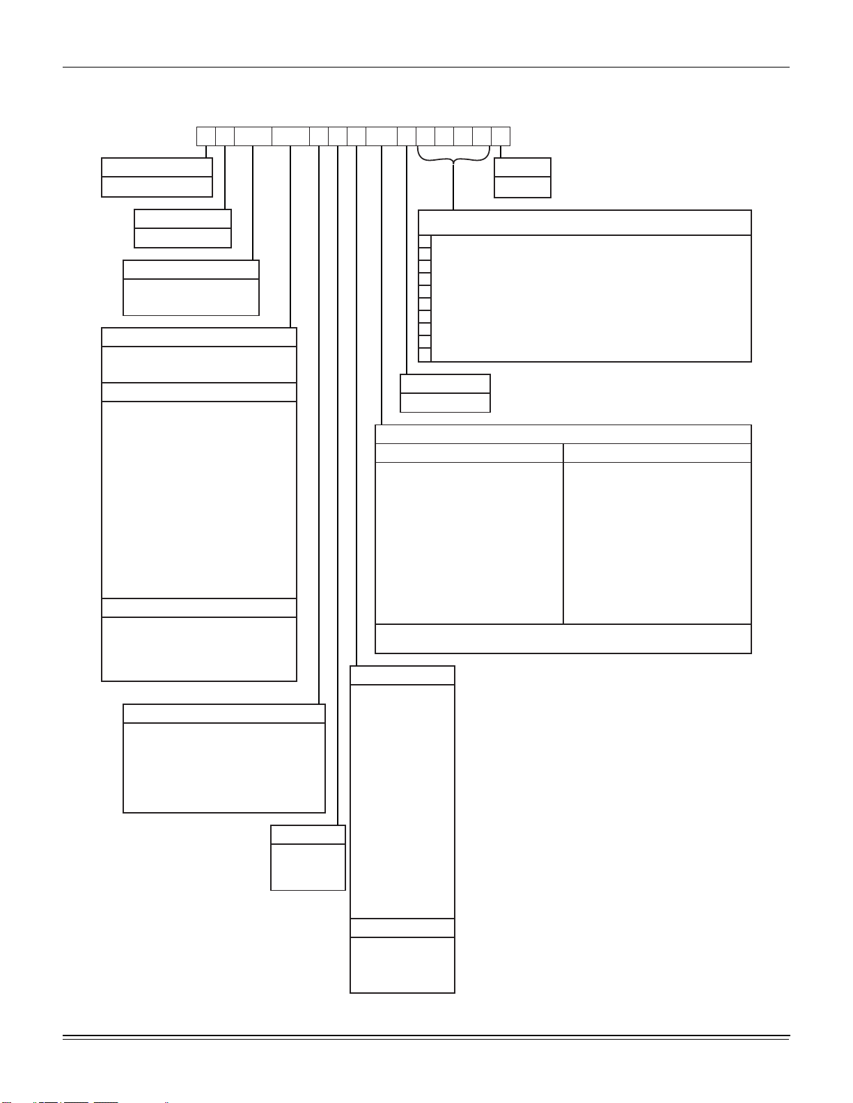
TABLE OF CONTENTS
General . . . . . . . . . . . . . . . . . . . . . . . . . . . . . . . . . . . . . . . . . . 2
Installation. . . . . . . . . . . . . . . . . . . . . . . . . . . . . . . . . . . . . . . . 5
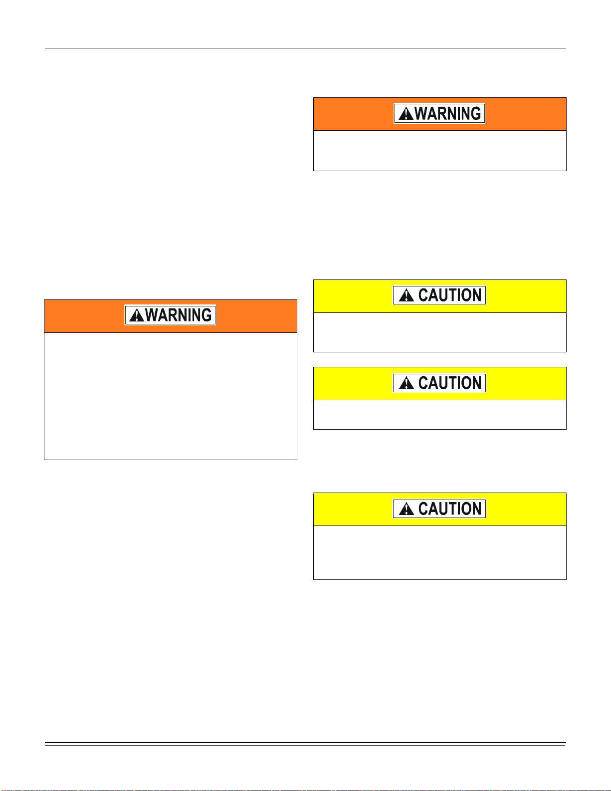
Installation Safety Information. . . . . . . . . . . . . . . . . . . . . . . 5
Limitations. . . . . . . . . . . . . . . . . . . . . . . . . . . . . . . . . . . . . . 5
Location. . . . . . . . . . . . . . . . . . . . . . . . . . . . . . . . . . . . . . . . 7
Rigging And Handling . . . . . . . . . . . . . . . . . . . . . . . . . . . . . 7
Ductwork. . . . . . . . . . . . . . . . . . . . . . . . . . . . . . . . . . . . . . 12
Condensate Drain. . . . . . . . . . . . . . . . . . . . . . . . . . . . . . . 12
Compressors. . . . . . . . . . . . . . . . . . . . . . . . . . . . . . . . . . . 12
Filters . . . . . . . . . . . . . . . . . . . . . . . . . . . . . . . . . . . . . . . . 13
Power And Control Wiring. . . . . . . . . . . . . . . . . . . . . . . . . 13
Optional Electric Heat . . . . . . . . . . . . . . . . . . . . . . . . . . . . 30
Options/Accessories . . . . . . . . . . . . . . . . . . . . . . . . . . . . . 33
Economizer And Power Exhaust Set Point
Adjustments . . . . . . . . . . . . . . . . . . . . . . . . . . . . . . . . . . . 33
Checking Supply Air CFM. . . . . . . . . . . . . . . . . . . . . . . . . 40
Operation . . . . . . . . . . . . . . . . . . . . . . . . . . . . . . . . . . . . . . . 41
Sequence Of Operations Overview. . . . . . . . . . . . . . . . . . 41
Cooling Sequence Of Operation. . . . . . . . . . . . . . . . . . . . 41
Reheat Mode Sequence Of Operation . . . . . . . . . . . . . . . 41
Cooling Operation Errors . . . . . . . . . . . . . . . . . . . . . . . . 42
Electric Heating Sequence Of Operations . . . . . . . . . . . . 43
Electric Heat Operation Errors . . . . . . . . . . . . . . . . . . . . 43
Gas Heating Sequence Of Operations . . . . . . . . . . . . . . . 44
Gas Heat Operation Errors . . . . . . . . . . . . . . . . . . . . . . . . 45
Flash Codes . . . . . . . . . . . . . . . . . . . . . . . . . . . . . . . . . . . 46
Resets. . . . . . . . . . . . . . . . . . . . . . . . . . . . . . . . . . . . . . . . 46
Heat Anticipator Setpoints. . . . . . . . . . . . . . . . . . . . . . . . . 46
Start-up (Cooling) . . . . . . . . . . . . . . . . . . . . . . . . . . . . . . . . . 46
Start-up (Gas Heat). . . . . . . . . . . . . . . . . . . . . . . . . . . . . . . . 46
Checking Gas Input. . . . . . . . . . . . . . . . . . . . . . . . . . . . . . . . 48
Charging The Unit. . . . . . . . . . . . . . . . . . . . . . . . . . . . . . . . . 49
Troubleshooting . . . . . . . . . . . . . . . . . . . . . . . . . . . . . . . . . . 49
Fan On And Off Delays. . . . . . . . . . . . . . . . . . . . . . . . . . . . . 57
LIST OF TABLES
1 ZR036-060 Unit Limitations. . . . . . . . . . . . . . . . . . . . . . . . 6
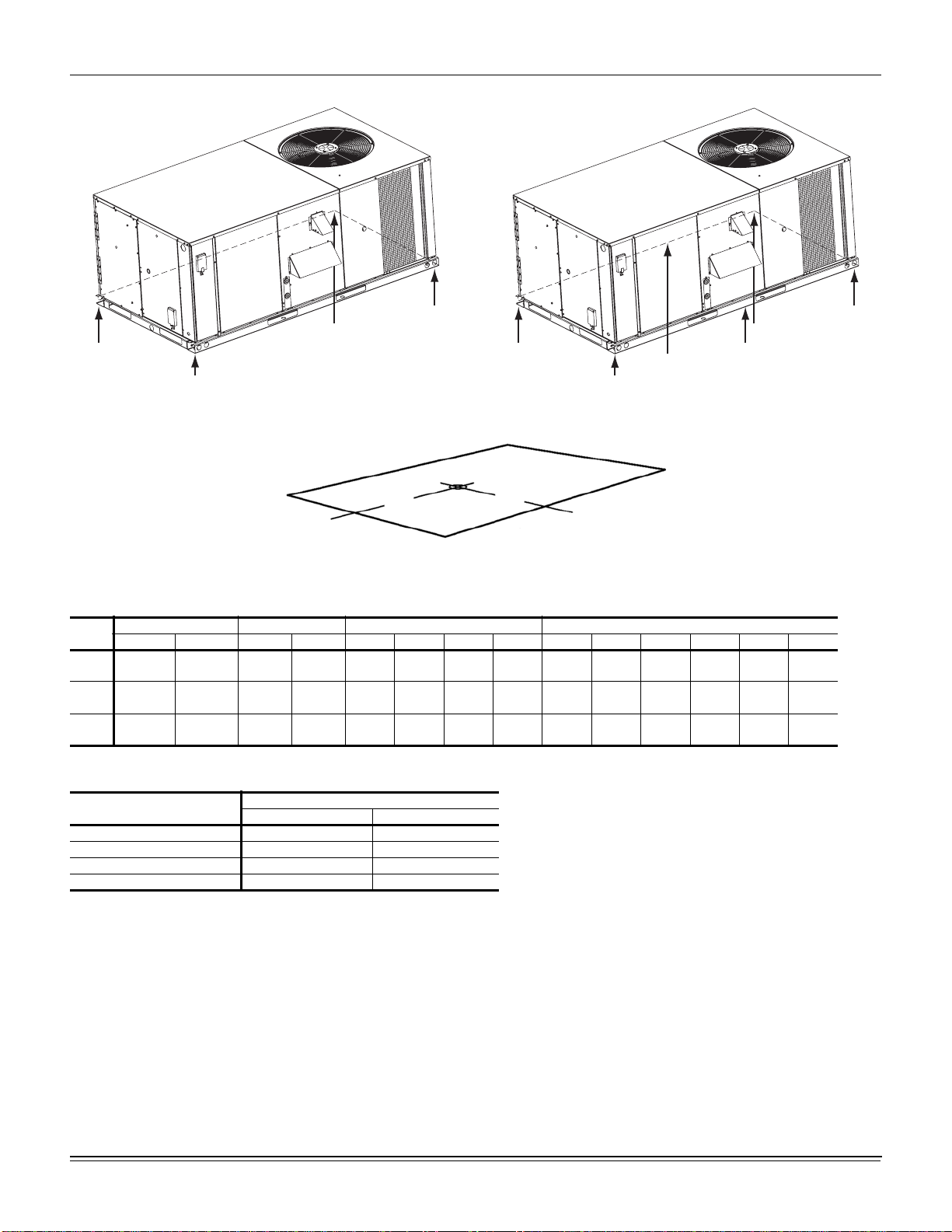
2 Weights and Dimensions . . . . . . . . . . . . . . . . . . . . . . . . . 8
3 ZR036-060 Unit Accessory Weights. . . . . . . . . . . . . . . . . 8
4 ZR036-060 Unit Clearances . . . . . . . . . . . . . . . . . . . . . . 10
5 ZR036-060 Utilities Entry . . . . . . . . . . . . . . . . . . . . . . . . 11
6 Control Wire Sizes . . . . . . . . . . . . . . . . . . . . . . . . . . . . . 14
7 Electrical Data . . . . . . . . . . . . . . . . . . . . . . . . . . . . . . . . . 16
8 ZR036-060 Physical Data . . . . . . . . . . . . . . . . . . . . . . . . 28
9 Electric Heat Minimum Supply Air. . . . . . . . . . . . . . . . . . 30
10 Gas Heat Application Data . . . . . . . . . . . . . . . . . . . . . . . 30
11 Gas Pipe Sizing - CapacIty of Pipe. . . . . . . . . . . . . . . . . 31
12 Altitude/Temperature Correction Factors . . . . . . . . . . . . 35
13 ZR Blower Performance Side Duct . . . . . . . . . . . . . . . . . 37
14 ZR Blower Performance Bottom Duct. . . . . . . . . . . . . . . 38
15 Belt Drive RPM Selection . . . . . . . . . . . . . . . . . . . . . . . . 39
16 Indoor Blower Specifications (Belt Drive) . . . . . . . . . . . . 39
17 Power Exhaust Specifications . . . . . . . . . . . . . . . . . . . . 40
18 Additional Static Resistance . . . . . . . . . . . . . . . . . . . . . . 41
19 Electric Heat Limit Setting. . . . . . . . . . . . . . . . . . . . . . . . 44
20 Electric Heat Anticipator Setpoints . . . . . . . . . . . . . . . . . 44
21 Single Stage Gas Heat Limit Control Setting . . . . . . . . . 46
22 2 Stage Gas Heat Limit Control Setting . . . . . . . . . . . . . 46
23 Gas Heat Anticipator Setpoints. . . . . . . . . . . . . . . . . . . . 46
24 Gas Rate-Cubit Feet per Hour . . . . . . . . . . . . . . . . . . . . 49
25 Unit Control Board Flash Codes . . . . . . . . . . . . . . . . . . . 57
26 Ignition Control Board Flash Codes . . . . . . . . . . . . . . . . 57
LIST OF FIGURES
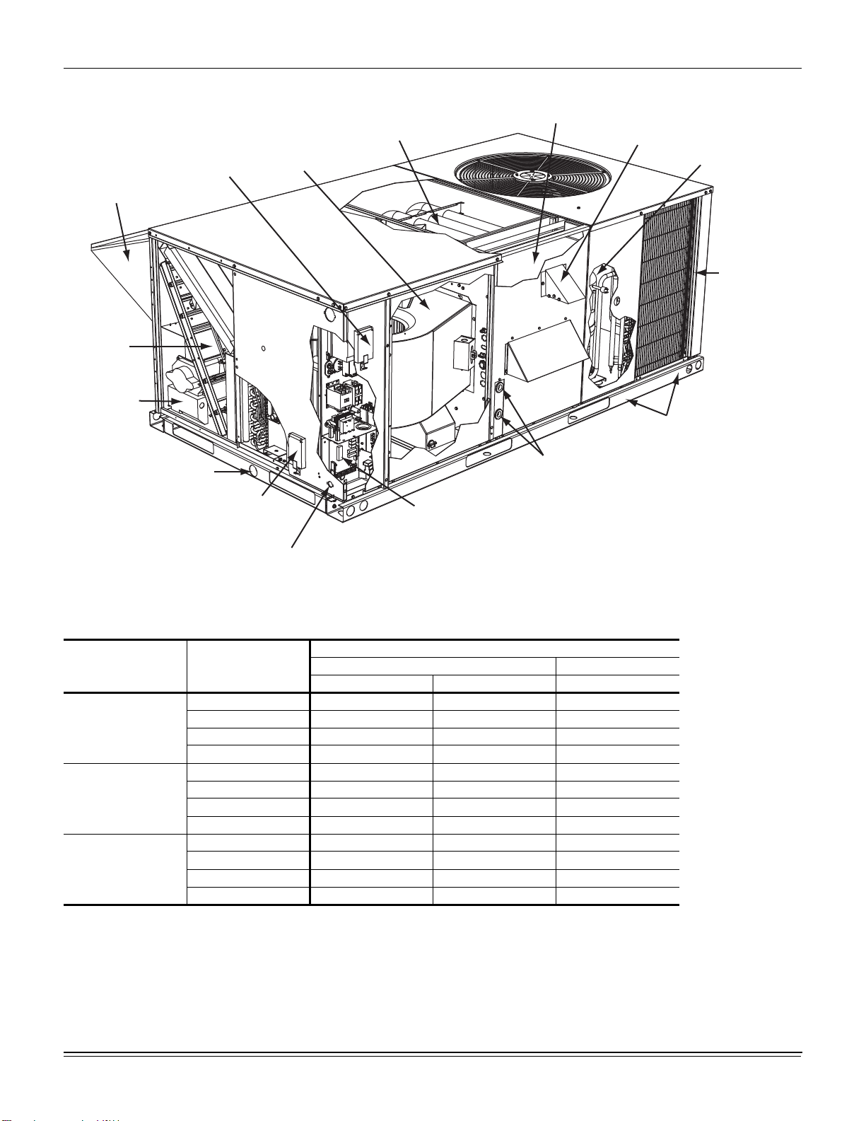
1 ZR036-060 Component Location. . . . . . . . . . . . . . . . . . . 6
2 Unit 4 Point Load Weight . . . . . . . . . . . . . . . . . . . . . . . . . 8
3 Unit 6 Point Load Weight . . . . . . . . . . . . . . . . . . . . . . . . . 8
4 Center of Gravity . . . . . . . . . . . . . . . . . . . . . . . . . . . . . . . 8
5 ZR036-060 Cooling Only/Electric Heat Front View
Physical Dimensions . . . . . . . . . . . . . . . . . . . . . . . . . . . . 9
6 ZR036-060 Cooling Only/Gas Heat Front View Physical
Dimensions . . . . . . . . . . . . . . . . . . . . . . . . . . . . . . . . . . . 9
7 ZR036-060 Fixed Outdoor Air Motorized Damper Rain
Hood Physical Dimensions . . . . . . . . . . . . . . . . . . . . . . 10
8 ZR036-060 Disconnect Location . . . . . . . . . . . . . . . . . . 10
9 ZR036-060 Unit Side Duct Openings. . . . . . . . . . . . . . . 11
10 ZR036-060 Roof Curb . . . . . . . . . . . . . . . . . . . . . . . . . . 11
11 Condensate Drain . . . . . . . . . . . . . . . . . . . . . . . . . . . . . 12
12 Compressor Restraining Bracket . . . . . . . . . . . . . . . . . . 13
13 Typical Field Power and Control Wiring. . . . . . . . . . . . . 15
14 Side Entry Gas Piping . . . . . . . . . . . . . . . . . . . . . . . . . . 31
15 Bottom Entry Gas Piping . . . . . . . . . . . . . . . . . . . . . . . . 31
16 Vent And Combustion Air Hood . . . . . . . . . . . . . . . . . . . 33
17 Enthalpy Set Point Chart . . . . . . . . . . . . . . . . . . . . . . . . 34
18 Honeywell Economizer Control W7212 . . . . . . . . . . . . . 34
19 Belt Adjustment . . . . . . . . . . . . . . . . . . . . . . . . . . . . . . . 34
20 Altitude/Temperature Correction Factors. . . . . . . . . . . . 35
21 Pressure Drop Across Coil. . . . . . . . . . . . . . . . . . . . . . . 40
22 Gas Valve Piping . . . . . . . . . . . . . . . . . . . . . . . . . . . . . . 45
23 Typical Single Stage Gas Valves. . . . . . . . . . . . . . . . . . 47
24 Typical 2 Stage Gas Valves. . . . . . . . . . . . . . . . . . . . . . 47
25 Proper Flame Adjustment . . . . . . . . . . . . . . . . . . . . . . . 48
26 Typical Flame Appearance . . . . . . . . . . . . . . . . . . . . . . 48
27 ZR036 (3.0 Ton) Operating Pressures. . . . . . . . . . . . . . 51
28 ZR048 (4.0 Ton) Operating Pressures. . . . . . . . . . . . . . 52
29 ZR060 (5.0 Ton) Operating Pressures. . . . . . . . . . . . . . 52
30 Unit Control Board . . . . . . . . . . . . . . . . . . . . . . . . . . . . . 57