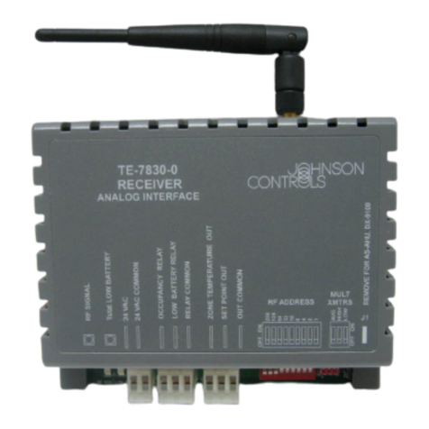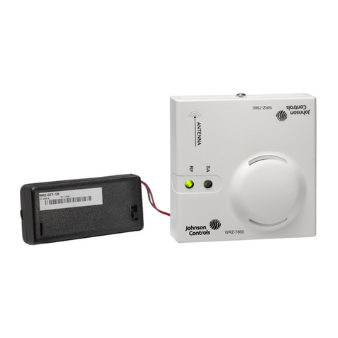
Note: Connecting the battery pack to the
receiver transforms the WRZ-7860-0 Receiver
into the WRZ-SST-120 Tool.
4. Turn the WRZ-SST-120 battery pack power switch to
ON.
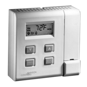
5. Turn the WRZ Series Sensor power switch to ON.
6. For a one to one wireless room sensing system,
place the WRZ-SST-120 Tool in the planned location
of the WRZ-7860-0 Receiver would be located and
place the WRZ Series Sensor in the area where you
intend to mount the sensor.
Note:
- If you use a ZFR or ZFR Pro Series Router
as a repeater in the final installation to
extend the operating range, place the
WRZ-SST-120 Tool in the same location
as the repeater. Use the WRZ Series
Sensor to verify the intended sensor
location, then use the WRZ Series Sensor
to stimulate and verify the intended
WRZ-7860-0 Receiver location.
- You cannot use a ZFR182x Pro Wireless
Field Bus Router as a repeater in a
WRZ-7860 application.
- For a ZFR or ZFR Pro Series Wireless Field
Bus System, place the WRZ Series Sensor
in the required location for a ZFR or ZFR
Pro Router, and place the WRZ-SST-120
Tool in the required location for a router
or coordinator.
7. Turn on the power switch of the test WRZ Series
Sensor and establish communication with the WRZ-
SST-120 Tool. When communication is established,
the RF signal strength LED on the WRZ-SST-120 Tool
blinks. 5 s after the you apply power, the red LED
on the WRZ Series Sensor flashes to indicate the
firmware revision. For example, three flashes of the
LED during the startup process indicates firmware
revision 3. If communication is not established
within 15 s, press the manual occupancy override
button on the WRZ Series Sensor to force another
communication attempt.
8. When the WRZ Series Sensor establishes
communication with the WRZ-SST-120 Tool, press
the manual occupancy override button for 5 s and
release to force the sensor into Rapid Transmit
Mode (RTM).
9. Hold the WRZ-SST-120 Tool in the required location
and record the number of times the RF signal
strength LED blinks over the course of 10 s. See
Table 1.. If the RF signal strength is less than good,
move the location of either device until indication
of an excellent or good RF signal strength. Move on
to the next location and repeat Steps 1 through 8
as necessary.
10. When testing is finished, turn off the battery switch
on the WRZ-SST-120 Tool and turn off the power
switch on the test WRZ Series Sensor.
Wireless signal strength
The RF signal strength LED indicates the strength of the
RF wireless signal between the sensor and its associated
sensing system receiver, expressed as excellent, good,
weak, or none. The WRZ-SST-120 Tool has an RF signal
strength LED that blinks off one, two, or three times
for every RF transmission to indicate the RF signal
strength between the sensor and the tool, or the router/
coordinator and the tool. See the following table.
Table 1: Wireless RF signal strength
Number of LED blinks RF signal strength
3 Excellent
2 Good
1 Weak
0 None
Rapid transmit mode (RTM) and RF
signal strength LEDs
A WRZ Series Sensor usually transmits every 60 s or 120
s. If you press and hold the manual occupancy override
button on the WRZ Series Sensor for 5 s and then release
it, this forces the sensor into RTM. In RTM, a WRZ Series
Sensor sends an RF data transmission once every 10
s. The sensor remains in RTM for up to a total of 30 RF
transmissions. After each RF transmission, the RF signal
strength LED of the sensor flashes (LED off to on) to
indicate the RF signal strength between the sensor and
WRZ-SST-120 Tool. The WRZ-SST-120 Tool blinks (LED on to
off) to indicate the wireless RF signal strength.
Repair information
If the WRZ-SST-120 Wireless Sensing System Tool fails
to operate within its specifications, replace the unit. For
a replacement WRZ-SST-120 Tool, contact the nearest
Johnson Controls representative.
Batteries
Two AA alkaline batteries are supplied with the WRZ-
SST-120 Wireless Sensing System Tool. Replace the
batteries with high-quality AA alkaline batteries as
necessary. Ensure to install the batteries in the correct
polarity. Replace both batteries at the same time.
Note: Batteries removed from this device must be
recycled or disposed of in accordance with local,
regional, and national regulations. Only certified
technicians or qualified building maintenance
personnel should service Johnson Controls products.
You can substitute lithium batteries with a maximum
cell voltage of 1.5 volts to extend the period between
battery replacement. Do not mix lithium and alkaline
batteries in this device.
Troubleshooting
See the following table for a list of documents containing
additional information on products and systems related to
the WRZ-SST-120 Wireless Sensing System Tool.
WRZ-SST-120 Wireless Sensing System Tool Installation Guide2
