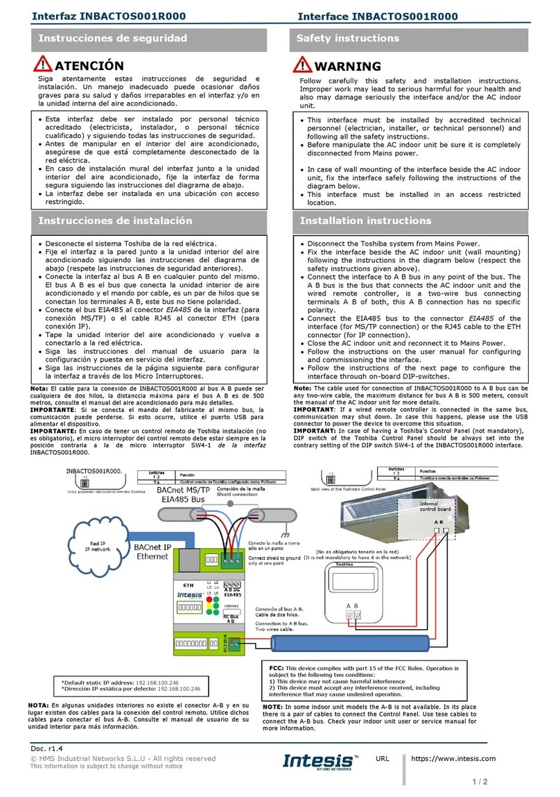
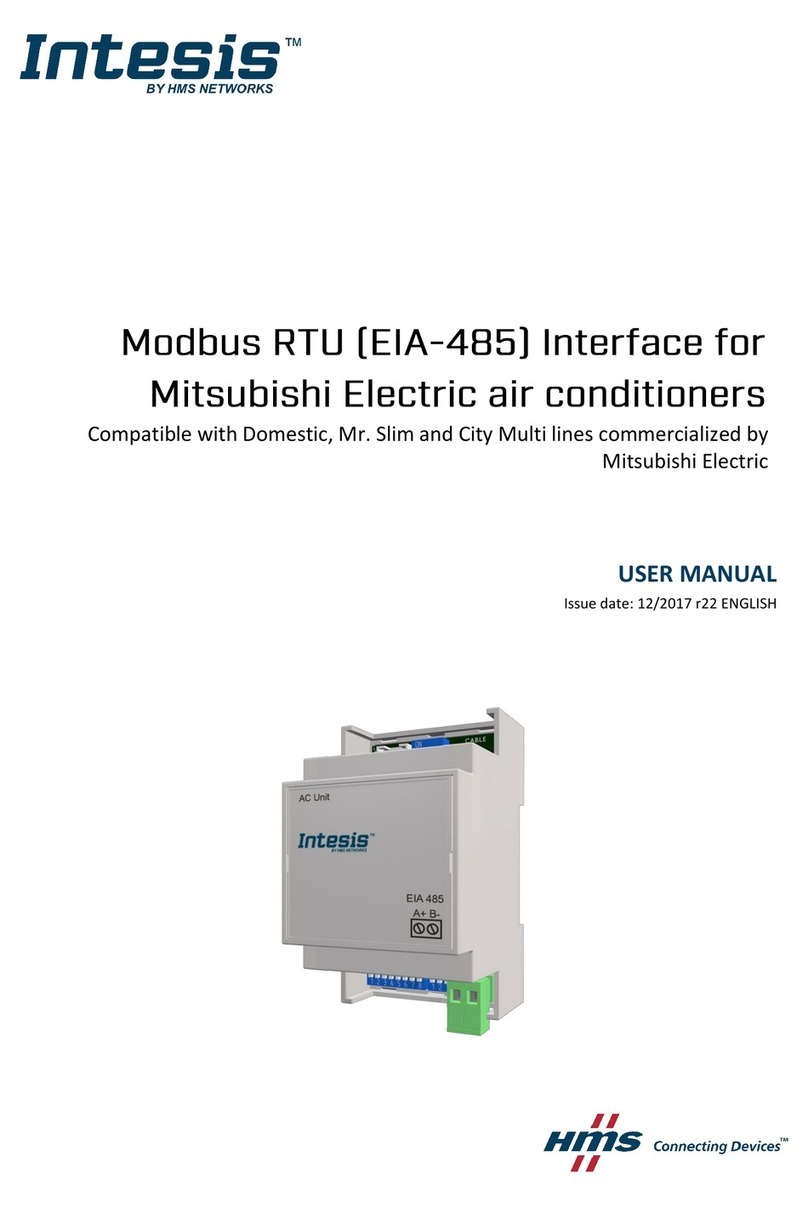
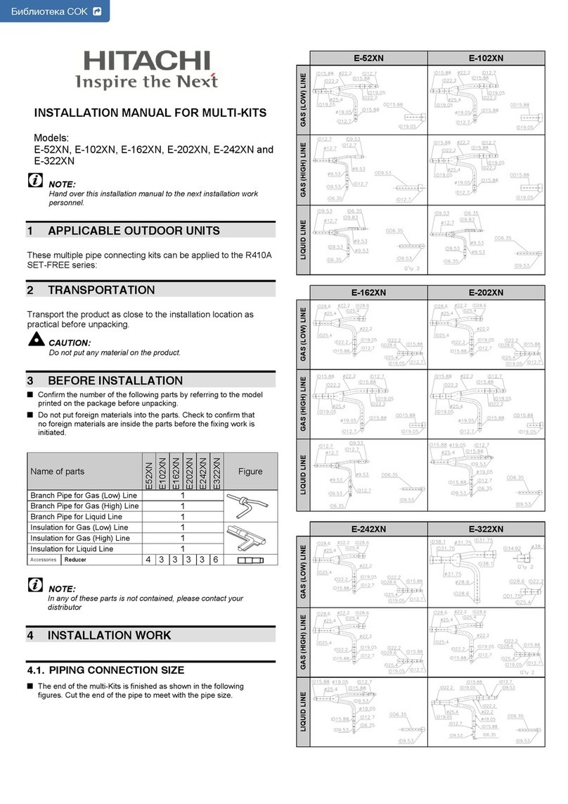
HMS Networks Intesis AC Cloud Control User manual

Device Configuration
Issue date: 10/2020
V1.0

Device Configuration 1.0
© HMS Industrial Networks S.L.U - All rights reserved
This information is subject to change without notice
URL https://www.intesis.com
2 / 24
Important User Information
Disclaimer
The information in this document is for informational purposes only. Please inform HMS
Industrial Networks of any inaccuracies or omissions found in this document.
HMS Industrial Networks disclaims any responsibility or liability for any errors that may appear
in this document. HMS Industrial Networks reserves the right to modify its products in line
with its policy of continuous product development. The information in this document shall
therefore not be construed as a commitment on the part of HMS Industrial Networks and is
subject to change without notice. HMS Industrial Networks makes no commitment to update
or keep current the information in this document.
The data, examples and illustrations found in this document are included for illustrative
purposes and are only intended to help improve understanding of the functionality and
handling of the product. In view of the wide range of possible applications of the product, and
because of the many variables and requirements associated with any particular
implementation, HMS Industrial Networks cannot assume responsibility or liability for actual
use based on the data, examples or illustrations included in this document nor for any
damages incurred during installation of the product. Those responsible for the use of the
product must acquire sufficient knowledge in order to ensure that the product is used correctly
in their specific application and that the application meets all performance and safety
requirements including any applicable laws, regulations, codes and standards. Further, HMS
Industrial Networks will under no circumstances assume liability or responsibility for any
problems that may arise as a result from the use of undocumented features or functional side
effects found outside the documented scope of the product. The effects caused by any direct
or indirect use of such aspects of the product are undefined and may include e.g. compatibility
issues and stability issues.

Device Configuration 1.0
© HMS Industrial Networks S.L.U - All rights reserved
This information is subject to change without notice
URL https://www.intesis.com
3 / 24
INDEX
1. Description..............................................................................................................................................4
1.1 Introduction .......................................................................................................................................4
1.2 About this document.........................................................................................................................4
1.3 What is needed.................................................................................................................................4
2. AC Cloud Control Button.......................................................................................................................6
2.1 Reset Wi-Fi settings..........................................................................................................................7
2.2 WPS mode........................................................................................................................................8
2.3 Change Wi-Fi channel ......................................................................................................................9
2.4 Autolearning................................................................................................................................... 10
3. Configuration....................................................................................................................................... 12
3.3 Automatic....................................................................................................................................... 15
3.4 Manual ........................................................................................................................................... 17
3.5 WPS............................................................................................................................................... 19
3.6 Settings.......................................................................................................................................... 21
4. LED status information....................................................................................................................... 23
4.1 LED status during Wi-Fi configuration ........................................................................................... 23
4.2 LED status during IR configuration (Autolearning mode) .............................................................. 23
4.3 LED status during working mode................................................................................................... 24

Device Configuration 1.0
© HMS Industrial Networks S.L.U - All rights reserved
This information is subject to change without notice
URL https://www.intesis.com
4 / 24
1. Description
1.1 Introduction
AC Cloud Control is the perfect IoT solution for professional AC management. It has been
developed along with the mayor AC manufacturers and offers the possibility to control almost
any domestic, commercial or VRF AC unit in the market from a generic dashboard available
for Android, iOS or in any web browser.
The AC Cloud Control system offers many functionalities covering different needs like energy
saving and air conditioner maintenance just to name some of them. All these functionalities
make the product the best professional solution for offices, stores, schools or any other
commercial building.
Figure 1.1 AC Cloud integration.
1.2 About this document
This document describes how to configure the AC Cloud Control device It contains the
meaning of the feedback light from AC Cloud Control LED during the configuration process
and working mode
1.3 What is needed
In order to use AC Cloud Control system is needed, at least, the following:
•AC Control device.
Before start using AC Cloud Control is needed to acquire (if the user hasn’t done yet)
an AC Cloud Control device
1
. In addition, is necessary be close to it (See Figure 1.2)
1
AC Cloud Control devices can be purchased in your usual air conditioner or heat pump reseller center.

Device Configuration 1.0
© HMS Industrial Networks S.L.U - All rights reserved
This information is subject to change without notice
URL https://www.intesis.com
5 / 24
Figure 1.2Get close to the device.
•Make sure to buy the right device.
Remember that there are the Universal and the Band Specific Wi-Fi Controllers
available for each manufacturer and type of climate system, check the compatibility.
•Internet access
2
.
The AC Cloud Control devices must be connected to internet using Wi-Fi, therefore
make sure the Wi-Fi signal reaches the device location (See Figure 1.3).
Figure 1.3 Check Wi-Fi Signal.
•Device with Internet access:
A device with internet access is needed (Smartphone or Tablet).
Make sure the smartphone or tablet used is Android or iOS compatible.
In addition, double check that the data is turned off and Wi-Fi is turned on.
2
Costs related with Internet access are not included in the AC Cloud Control price. Ask your Internet Service Provider about the
associated costs of your Internet connection.
<2m
OK
Table of contents
Other HMS Networks Air Conditioner Accessories manuals
Popular Air Conditioner Accessories manuals by other brands
Mitsubishi Electric
Mitsubishi Electric PAC-SNH11HS-E installation manual
Unitary products group
Unitary products group 2CE Series installation instructions
Qlima
Qlima EU-ODZ104 user manual

Tecnosystemi
Tecnosystemi smart clima SCD500163 user manual

Waeco
Waeco AirCon Service Center ASC 5300 G operating manual
American Standard
American Standard BAYSQRD001AA Installer's guide
Bimar
Bimar AP11 Instruction booklet
Mitsubishi
Mitsubishi PAC-SJ41TM-E installation manual
Tecnosystemi
Tecnosystemi Smart Clima SCD500084 user manual
Samsung
Samsung MIM-H04U User & installation manual

Waeco
Waeco AirConServiceCenter ASC 3500 G LE operating manual
Fujitsu
Fujitsu UTZ-KXGC installation manual
