manuals.online logo
Brands
  1. Home
  2. •
  3. Brands
  4. •
  5. Johnson Controls
  6. •
  7. Control Unit
  8. •
  9. Johnson Controls Autocall MX Indoor Isolated Callpoint User manual

Johnson Controls Autocall MX Indoor Isolated Callpoint User manual

Cautions, warnings, and regulatory information
READ AND SAVE THESE INSTRUCTIONS Follow the instructions in this
installation manual. These instructions must be followed to avoid damage
to this product and associated equipment. Product operation and reliability
depend upon proper installation.
DO NOT INSTALL ANY AUTOCALL™ PRODUCT THAT APPEARS
DAMAGED Upon unpacking your Autocall product, inspect the
contents of the carton for shipping damage. If damage is apparent,
immediately file a claim with the carrier and notify an authorized
Autocall product supplier.
ELECTRICAL HAZARD Disconnect electrical field power when
making any internal adjustments or repairs. All repairs should be
performed by a representative or an authorized agent of your local
Autocall product supplier.
STATIC HAZARD Static electricity can damage components. Handle
as follows:
• Ground yourself before opening or installing components.
• Prior to installation, keep components wrapped in anti-static
material at all times.
Indoor isolated callpoint
Figure 1: Indoor isolated callpoint
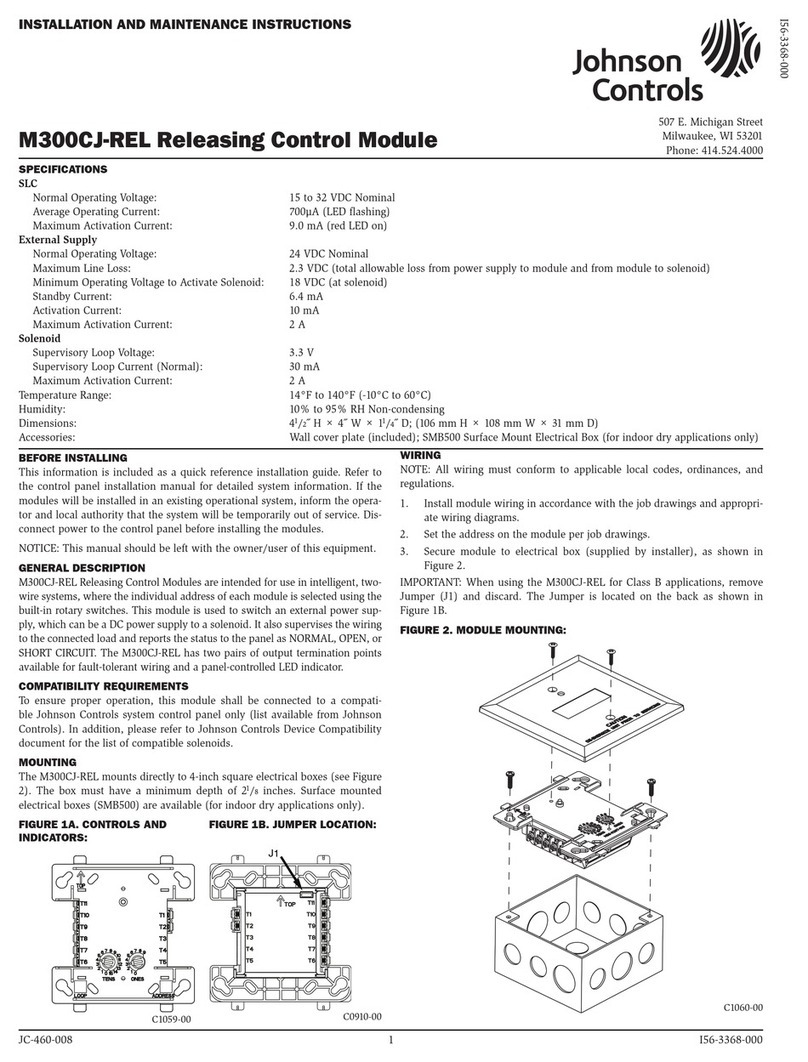
The indoor isolated callpoint is an addressable indoor manual callpoint. The
callpoint signals the condition of a switch contact that activates with a press
of a deformable element. After activation the callpoint can be reset. The unit
features a short-circuit isolator and is UL compliant. For details of the status
LED and activation see Table 4.
Table 1: Ordering information
Item Order number
MCP - Indoor isolator A4099-5208
Resettable element (pack of 1) 515.001.127
Back box A4099-9711
Glass element (pack of 5) 515.001.119
Installating the callpoint
1. Connect an 801AP MX Service Tool or an 850EMT into the programming
port, noting the orientation. Program the unit using the ID defined in the
site configuration.
2.
- To surface mount the callpoint, use the dedicated back box
(A4099-9711) to mount the callpoint to the wall.
- To flush mount the callpoint, use a standard single gang back box. The
back box must be at least 25 mm (0.98 in.) deep with fixing holes at
60.3 mm (2.37 in.) spacing.
3. Route the loop wiring through the back box.
4. Remove the callpoint sliding front plate and deformable element
assembly. This is described in the following section under 'replacing the
glass or deformable element'.
5. Connect the loop wiring to the push-fit connector, see Figure 2.
6. Connect the push-fit connector.
7. Fix the callpoint to the back box using the supplied screws through the
exposed fixing holes.
8. Re-fit the front plate assembly. Slide it into position then push upwards
until it clicks into place.
Figure 2: Installation
Table 2: Installation
Number Part
1 Programming port
2 Push-fit connector
Table 3: Field wiring
Connector Loop connection
A +L
B -L
C +R
D - R
579-1396AC Rev. A
MX Indoor Isolated Callpoint
*05791396ACA*
Operation
Reading the LED status
Table 4: LED status
Status LED
Normal LED OFF
Short circuit LED ON - YELLOW
Activated LED ON - RED
Activating the callpoint
Press the large dot. A spring pushes the plastic element downwards, this
closes a switch and triggers a signal to the control panel.
Testing the callpoint
1. Insert the test/reset key into the slot in the bottom of the unit and pull
the sliding plate downwards.
Note: This may cause an alarm.
2. Remove the key. The deformable element facilitates testing by activating
the callpoint as normal. This is non-destructive.
Resetting the callpoint
1. Insert the test/reset key into the slot in the bottom of the unit and pull
the sliding plate downwards. The element can now snap back to its non-
deformed state.
2. To close the callpoint, push the sliding plate upwards until it snaps into
place. See Figure 3.
Replacing the glass of deformable element
1. Insert the test/reset key into the slot in the bottom of the unit and pull
the sliding plate down until it seperates from the unit.
2. Remove the deformable element, pulling away the bottom first. Fit the
replacement then push the sliding plate upwards until it snaps back into
place.
Figure 3: Resetting the callpoint
Specifications
Table 5: Specifications
Specification Rating
System compatibility Compatible with Simplex 4100ES and 4010ES
Environment Indoor applications only
Operating temperature -10°C to +55°C
Storage temperature -30°C to +70°C
Material Flame retardant ABS
Operating humidity Up to 90% non-condensing
Dimensions (H x W x D) 93 mm x 89 mm x 27.5 mm
(3.7 in. x 3.5 in. x 1.1 in.)
Weight 110 g (3.9 oz.)
Mounting Surface or flush
Standby current @ 40 VDC 0.3 mA
Alarm current @ 40 VDC 2.456 mA
579-1396AC Rev. A
© 2021 Johnson Controls. All rights reserved. All specifications and other information shown were current as of document revision and are subject to change without notice.
Additional listings may be applicable, contact your local Autocall product supplier for the latest status. Listings and approvals under Tyco Fire & Security GmbH, and the product
names listed in this material are marks and/or registered marks. Unauthorized use is strictly prohibited. NFPA 72 and National Fire Alarm Code are registered trademarks of the
National Fire Protection Association (NFPA).

This manual suits for next models

1

Other Johnson Controls Control Unit manuals
Johnson Controls V46SA Series User manual

Johnson Controls

Johnson Controls V46SA Series User manual

Johnson Controls GH-5000 User manual

Johnson Controls

Johnson Controls GH-5000 User manual

Johnson Controls Tyco DV-5a Series User manual

Johnson Controls

Johnson Controls Tyco DV-5a Series User manual

Johnson Controls MP8000 Series User manual

Johnson Controls

Johnson Controls MP8000 Series User manual

Johnson Controls VP101DBB User manual

Johnson Controls

Johnson Controls VP101DBB User manual

Johnson Controls System 450 Series User manual

Johnson Controls

Johnson Controls System 450 Series User manual

Johnson Controls PENN P70 Series Manual

Johnson Controls

Johnson Controls PENN P70 Series Manual

Johnson Controls S300 Series Assembly instructions

Johnson Controls

Johnson Controls S300 Series Assembly instructions

Johnson Controls Tyco HSM3408 User manual

Johnson Controls

Johnson Controls Tyco HSM3408 User manual

Johnson Controls FX-PCX2721 User manual

Johnson Controls

Johnson Controls FX-PCX2721 User manual

Johnson Controls MS-IOM2710-0U User manual
Johnson Controls

Johnson Controls MS-IOM2710-0U User manual

Johnson Controls NIE39 User manual

Johnson Controls

Johnson Controls NIE39 User manual
Johnson Controls VP140 User manual

Johnson Controls

Johnson Controls VP140 User manual

Johnson Controls LP-FXGPRSU-0 User manual

Johnson Controls

Johnson Controls LP-FXGPRSU-0 User manual

Johnson Controls Digital Vision Network 5000 Series Quick start guide

Johnson Controls

Johnson Controls Digital Vision Network 5000 Series Quick start guide

Johnson Controls 300 Series User manual
Johnson Controls

Johnson Controls 300 Series User manual

Johnson Controls IOM1711 User manual

Johnson Controls

Johnson Controls IOM1711 User manual

Johnson Controls Tyco DV-5a Series User manual

Johnson Controls

Johnson Controls Tyco DV-5a Series User manual
Johnson Controls GS Series User manual

Johnson Controls

Johnson Controls GS Series User manual

Johnson Controls System 350 Y350R Service manual

Johnson Controls

Johnson Controls System 350 Y350R Service manual

Johnson Controls IOM3731 User manual

Johnson Controls

Johnson Controls IOM3731 User manual

Johnson Controls Tyco RSV-1 User manual

Johnson Controls

Johnson Controls Tyco RSV-1 User manual

Johnson Controls MS-IOM3723 User manual

Johnson Controls

Johnson Controls MS-IOM3723 User manual

Johnson Controls Mercury P2000 CKM-MR16IN Manual

Johnson Controls

Johnson Controls Mercury P2000 CKM-MR16IN Manual

Popular Control Unit manuals by other brands

Spirax Sarco TD3-3 Installation and maintenance instructions

Spirax Sarco

Spirax Sarco TD3-3 Installation and maintenance instructions

hager TRB221A-5A manual

hager

hager TRB221A-5A manual

Whelen Engineering Company 295HFSA6 installation guide

Whelen Engineering Company

Whelen Engineering Company 295HFSA6 installation guide

Festo VEAB Series operating instructions

Festo

Festo VEAB Series operating instructions

Hama 00176592 operating instructions

Hama

Hama 00176592 operating instructions

FONESTAR CDM-1200 quick start guide

FONESTAR

FONESTAR CDM-1200 quick start guide

Dräger Evita V Series quick start guide

Dräger

Dräger Evita V Series quick start guide

tams elektronik KSM-4 manual

tams elektronik

tams elektronik KSM-4 manual

National Instruments NI 9472 operating instructions

National Instruments

National Instruments NI 9472 operating instructions

Kontron COMe-mAL10 user guide

Kontron

Kontron COMe-mAL10 user guide

Venmar DECO-TOUCH WALL CONTROL Installation and owner's guide

Venmar

Venmar DECO-TOUCH WALL CONTROL Installation and owner's guide

Elvaco CMi4140 user manual

Elvaco

Elvaco CMi4140 user manual

KWC RONDA ZANMW0030 Installation and operating instructions

KWC

KWC RONDA ZANMW0030 Installation and operating instructions

Texas Instruments TPA6047A4 user guide

Texas Instruments

Texas Instruments TPA6047A4 user guide

Uhlenbrock Elektronik IntelliSound manual

Uhlenbrock Elektronik

Uhlenbrock Elektronik IntelliSound manual

Troxler 3411-B Manual, operation and installation

Troxler

Troxler 3411-B Manual, operation and installation

Swagelok IPT Series manual

Swagelok

Swagelok IPT Series manual

National Instruments NI FlexRIO PXI-7952R installation guide

National Instruments

National Instruments NI FlexRIO PXI-7952R installation guide

manuals.online logo
manuals.online logoBrands
  • About & Mission
  • Contact us
  • Privacy Policy
  • Terms and Conditions

Copyright 2025 Manuals.Online. All Rights Reserved.