Johnson Controls Facility Explorer Service manual

Technical Bulletin Network Room Module
Issue Date January 22, 2010
©2010 Johnson Controls, Inc.
Code No. LIT-12011258
Network Room Module
Introduction to Network Room Module (NRM).....................................3
Concepts.............................................................................................................. 4
Features.............................................................................................................................4
Controls..............................................................................................................................5
Functions and Setup of the Network Room Module...........................................................6
Network Room Module Parameters (Room Sensor Object) ............................................13
Installing and Commissioning the Network Room Module..............15
Introduction........................................................................................................ 15
North American Emissions Compliance...........................................................................15
Key Concepts..................................................................................................... 16
Location of the Network Room Module............................................................................16
Dimensions of the Network Room Module.......................................................................17
Wiring...............................................................................................................................18
Addressing.......................................................................................................................19
Service Port......................................................................................................................20
Commissioning the Network Room Module.....................................................................22
Procedure Overview.........................................................................................................23
Detailed Procedures.......................................................................................... 23
Opening the Network Room Module................................................................................23
Mounting the NRM Directly on a Wall Surface.................................................................24
Mounting the NRM (80 x 80 mm) on a Wall Surface Using the
Plastic Base for Surface Mounting...................................................................................26
Mounting the NRM (80 x 80 mm) on a Recessed Wall Box.............................................27
Commissioning the NRM Module.....................................................................................29

Network Room Module Technical Bulletin2
Troubleshooting...................................................................................30
Specifications and Ordering Codes....................................................31
Specifications and Technical Data................................................................... 31
Ordering Codes ................................................................................................. 32

Network Room Module Technical Bulletin 3
Introduction to Network Room
Module (NRM)
Network Room Modules (NRMs) are electronic, wall-mountable
temperature sensors designed to be used with the Facility Explorer field
controllers.
Note: See the Specifications and Ordering Codes section for details
about compatible controllers.
All NRM models monitor room or space temperature. In addition, you can
order NRMs with a backlit Liquid Crystal Display (LCD) to display the
room temperature and local setpoint. Graphical display symbols can
indicate fan speed selection and the need for maintenance. Optional
operating controls include a dial to locally adjust the space temperature
setpoint, a push button to manually override the fan speed, and a push
button to select Fahrenheit (°F) and Celsius (°C) units of measure.
The NRM connects to the Remote Display link of the Facility Explorer
field controller. Terminals are located in the mounting base for ease of
wiring. The NRM is enclosed in an attractively styled plastic housing,
which easily mounts on a wall.
Figure 1: Network Room Modules

Network Room Module Technical Bulletin4
Concepts
Features The NRM (Figure 2) is styled to blend with the decor of today’s
commercial and public buildings. Terminals are located in the mounting
base for ease of wiring. The module also has a built-in temperature sensor
used to measure space temperature for display and transmission to the
connected controller. If the controller has its own space temperature
sensor, then it communicates its temperature values to the module for
display.
Located on the front of the room command module are the operating
controls and an LCD with three numerical digits and various operating
mode symbols. With the NRM, you can:
•view the space (room) temperature
•view and manually adjust the space temperature setpoint
•manually override the speed of the fan in the controlled equipment
•see when the controller is in the Off mode
•see when a maintenance condition exists
•request the temporary occupied mode during unoccupied or standby
mode operation by pressing a push button or rotating the dial
•change the temperature display units from °F to °C (North American
models only)
Some of these functions may not be available or are limited by the
configuration of the module or controller.

Network Room Module Technical Bulletin 5
The NRM has a service port (located on the lower edge of the module).
Use the service port to gain access to the serial bus for the host FX field
controller. Two types of service ports are available (see Figure 2 for
service port location).
•The service port for NRM model LP-NRM0xx-000C is a 4-pin
connector and is used to interface with the FX Programming Key.
•The service port for NRM models LP-NRM5xx-000C and
LP-NRM6xx-000C is a 6-pin Modular Jack connector and is used to
interface with the Medium User Interface (MUI).
Figure 2: Features of the Network Room Module
Controls Table 1 shows how the dial and buttons are used in the NRM.
Table 1: Controls
Control Description
Setpoint Dial
Used to change the temperature setpoint
value: turning right increases the setpoint and
turning left decreases the setpoint. When you
move the dial, the display shows the current
space temperature setpoint.
Fan Push Button
Used to override the fan status from Auto to
Off, low, medium, or high speed.
°F/°C
°F/°C Push Button
Used to toggle the temperature display units
between °C and °F.

Network Room Module Technical Bulletin6
Figure 3 shows the layout and symbols of the LCD, and Table 2 describes
the symbols.
Figure 3: LCD Symbol Options
Table 2: Symbols on the LCD
Control Description
Temperature display digits
Fan speed status bars – low, medium, and high speed (high
speed shown)
°CCelsius temperature unit
°FFahrenheit temperature unit
AUTO The Auto icon indicates that the fan is in auto mode.
OFF The Off icon indicates that the fan has been manually set to Off
(not running).
The Maintenance icon indicates an off-normal condition that
requires attention.
The Occupancy Mode icon indicates the occupied/unoccupied
mode of the controller (LP-NRM5xx-000C and LP-NRM6xx-
000C Series only).
Functions and Setup of the Network Room Module
The NRM is a network device with no hardware inputs or outputs and
connects to the Facility Explorer controller via the display (or local link)
bus. All the communication access and setup of the NRM is done through
the controller where the NRM is connected. The configuration properties
of the NRM are set in the Room Sensor object in the controller when the
control application for the controller is generated in the FX Builder tool.
When the application is downloaded to the controller, you use the
FX CommPro N2, LON, or BACnet commissioning tool to monitor the
network variables of the NRM in the Room Sensor object through the
network profile of the controller.
This section describes the various functions and display features of the
NRM, the network variables used by each function, and the configuration
properties used to set up each function.

Network Room Module Technical Bulletin 7
See Network Room Module Parameters (Room Sensor Object) for a
detailed list of the variables and properties of the NRM. The names of the
network variables and configuration properties appear in boldface type
throughout this document.
Note: After a power failure, the NRM restarts using the values in its
configuration properties and any setpoint changes or fan speed overrides
are cancelled. In particular, if you set the Setpoint Configuration to
absolute, you should also set the Default Absolute Setpoint for the
controlled space in case of a power interruption. The factory set value is
21°C (70°F).
Display
The NRM models with display are factory-configured to show space
temperature. The models with the fan speed override function are
configured for three-speed fan control. As soon as you connect the NRM
to a controller with a configured Room Sensor object, the properties in the
Room Sensor object transmit to the NRM and replace the factory set
values.
You can change the setpoint temperature by rotating the dial. The space
setpoint value appears and blinks for a few seconds, waiting for a change.
The NRM then confirms the change to the controller and displays the
space temperature again (if enabled).
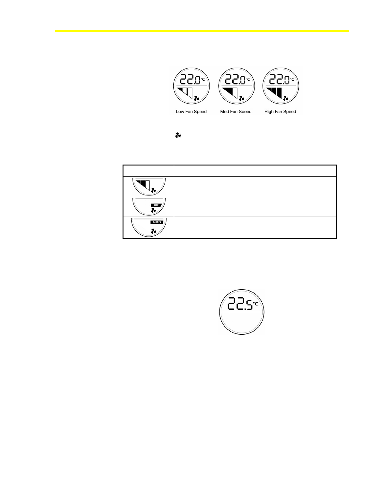
In models with the fan speed override function, you can change the fan
speed by pressing the fan push button. The fan status display cycles
through the steps AUTO, OFF, Low Speed, Medium Speed, and High
Speed, according to the fan configuration.
If you set the Enable Space Temperature Display configuration property
to disabled (OFF), the NRM always shows the space setpoint temperature
and does not show the actual space temperature.
Note: The network variable output Space Temperature Output
always sends its internal space temperature value, even if the space
temperature does not appear.
Depending on the values of the Setpoint Configuration and
Temperature Units configuration properties, the display shows either the
absolute setpoint or the setpoint offset. The absolute setpoint is stored in
the Setpoint Output (Absolute) network variable output. The setpoint
offset is stored in the Setpoint Output (Offset) network variable output.
Some space setpoint temperature display examples are shown in Figure 4
and Figure 5.

Network Room Module Technical Bulletin8
Figure 4: Absolute Setpoint Values in Celsius and Fahrenheit Units
Figure 5: Relative (Offset) Setpoint Values in Celsius Units
Setpoint Adjustment
You can change the value of the setpoint by rotating the NRM dial to the
right to increase the setpoint, and to the left to decrease the setpoint. The
display stops at the high and low limits. The high and low limits are:
•±3°C (±5°F) - if the NRM is configured to display the setpoint offset,
or
•the values are defined in the Space Temperature Setpoint Low Limit
and Space Temperature Setpoint High Limit configuration
properties, if the NRM is configured to display the absolute setpoint.
The default absolute setpoint limits are 12 and 28°C (53.5 and 82.5°F).
When you adjust the setpoint, the value you enter is transmitted to the
controller via either the network variable output Setpoint Output
(Absolute) or Setpoint Output (Offset), depending on the value of
Setpoint Configuration. The network variable that is not used is set to an
invalid value.
The Setpoint Output (Absolute) value when the NRM starts up is
determined by the Default Absolute Setpoint value in the Room Sensor
object in the controller. The factory set value is 21°C (70°F). The Setpoint
Output (Offset) value is zero at startup.
Fan Speed Adjustment
In NRM models with the fan speed override function, you can change the
speed of the fan by pressing the fan push button until the desired speed
appears on the fan speed bars. See Figure 6. The override value then
transmits to the controller via the network variable output Fan Speed
Override. When the fan is set to Off mode by an override command, the
OFF symbol appears.

Network Room Module Technical Bulletin 9
When the fan is set to Auto mode, the Auto symbol appears, and the
controller determines the fan speed using its internal control algorithm.
Figure 6: Fan Speed Display in Manual Override
The fan symbol ( ) is always shown, whether the fan is running or not.
Examples of the fan speed display are shown in Table 3.
Table 3: Examples of Fan Speed Display
Control Description
Fan speed was overridden to medium speed by the user.
Fan speed is overridden to OFF by the user.
Fan in AUTO mode – no override by user. The actual fan
speed is not shown.
The type of fan is configurable in the property Fan Configuration for:
•None (no fan)
There is no fan. The fan override function is disabled (Figure 7).
Figure 7: No Fan Display
•One speed
If you set the property to One speed fan, pressing the fan push button
cycles the fan status: AUTO, OFF, and ON. The display fills all three
fan bars to indicate the ON status.
•Two speed
If you set the property to Two speed fan, pressing the fan push button
cycles the fan status: AUTO, OFF, low, and high speed. The display
shows two fan bars for low speed and three bars for high speed.

Network Room Module Technical Bulletin10
•Three speed
If you set the property to Three speed fan, pressing the fan push
button cycles the fan status: AUTO, OFF, low, medium, and high
speed.
Occupancy Mode
The LED display indicates the Effective Occupancy Status when the
Enable Unoccupied State Blink configuration property is set to enabled
(ON) and the network variable input Effective Occupancy Status value
shows that the occupancy mode is UNOCCUPIED or STANDBY. See
Figure 8 and Table 4.
Figure 8: Occupancy Mode Icon for
LP-NRM5xx-000C and LP-NRM6xx-000C Series NRMs
Table 4: Effective Occupancy Status
NRM Series Effective
Occupancy
Status
Icon/Description
Occupied The display remains on.
LP-NRM0xx-000C Series Unoccupied or
Standby The display blinks off/on
approximately every
3 seconds.
Occupied
LP-NRM5xx-000C and
LP-NRM6xx-000C Series
Unoccupied or
Standby
This feature indicates to the unexpected occupant (or an occupant present
during nonstandard hours) that the controller is not in the OCCUPIED
mode. You can disable this feature by setting the Enable Unoccupied
State Blink configuration property to disabled (OFF).

Network Room Module Technical Bulletin 11
Temporary Occupied Mode
The Temporary Occupancy Mode Request output network variable
normally reflects the value of the Effective Occupancy Status input
network variable as received from the controller. In UNOCCUPIED or
STANDBY mode, you can force the Temporary Occupancy Mode
Request output variable to Temporary Occupied (BYPASS) mode for the
time duration (in minutes) set in the configuration property Temporary
Occupied Time. You achieve this Temporary Occupied mode when you
press the fan push button or rotate the setpoint dial. The BYPASS state of
the Temporary Occupancy Mode Request network variable is then
transmitted to the connected controller to set the occupancy status of the
controller to the Temporary Occupied (BYPASS) mode. When the
temporary occupied time expires, the value of Temporary Occupancy
Mode Request returns to the value of the Effective Occupancy Status
input variable. This operation depends on the correct configuration of the
application in the controller using FX Builder.
Off Mode
When the network variable input HVAC Application Mode has the OFF
(state 6) value, the display shows OFF in the upper display field to
indicate that no control action is possible.
Figure 9: OFF Mode Display (HVAC Application Mode)
Maintenance Icon
The maintenance icon ( ) appears on the display when the configuration
property Enable Maintenance Icon is enabled (ON) and one of the
following conditions exists:
•The network variable input Display Maintenance Icon is ON. The
control application in the controller determines the conditions for the
network variable to be on.
•The internal space temperature value, as seen in Space Temperature
Output, is unreliable (out of range).
•There is no communication with an FX controller.
You can choose not to display the maintenance icon on the NRM by
setting the configuration property Enable Maintenance Icon to disabled
(OFF).

Network Room Module Technical Bulletin12
Back Light Time-out
The LCD is back-lit in the NRM and lights up when the fan or °F/°C push
button is pressed or the dial is turned. The back-light time-out is set in the
Back-light Time-out configuration property. The factory default setting is
30 seconds. A value of 0 disables the back-light; a value greater than 60
keeps the back-light permanently on.
Temperature Units on Display
In NRM models without the °F/°C push button, the temperature units on
the display are determined by the Temperature Units configuration
property.
In NRM models with the °F/°C push button, the Temperature Units
configuration property determines the temperature units on the display at
start-up, but the units are toggled between °F and °C by pressing the push
button.
Physical Address
The NRM has a physical address that you must set in the
PhysicalAddress configuration property in the Room Sensor object of the
FX controller.
Non-addressable NRM models have a fixed address of 191, which is the
default setting of the Room Sensor object. Addressable NRM models
include DIP switches, allowing you to set the physical address between
191 and 194.
Note: You must cycle power to the NRM (disconnect/reconnect the
NRM or cycle power to the field controller) for the address change to take
effect.

Network Room Module Technical Bulletin 13
Network Room Module Parameters (Room Sensor Object)
Table 5, Table 6, and Table 7 list the network variables and configuration
properties available in the NRM Room Sensor object. You must create an
instance of this object in the FX controller for the connected NRM. The
controller automatically transfers the configuration data to the NRM
module and transmits and receives the network variable information over
the local link bus.
Note: The configuration properties are also available as network
variable inputs so that they can be dynamically changed in the application
in the controller at runtime.
Table 5: Network Variable Inputs
Description Variable Name Data Type
Space Temperature Override SpaceTempOverride Analog – temperature
Effective Occupancy Status EffectOccupancyStatus1Enumeration – Occupancy
HVAC Application Mode HVACMode2Enumeration – HVAC Mode
Display Maintenance Icon MaintenanceIcon3Binary logic
1. 0=Occupied, 1=Unoccupied, 2=Temp.Occ (Bypass), 3=Standby, 4-255=Invalid (Null).
2. 6=Off, All except 6 and 255=On, 255=Invalid. (When Off, the LCD shows OFF.)
3. 0=Off, 1=On, 2 to 255=Invalid. (When On, the LCD shows the maintenance icon.)
Table 6: Network Variable Outputs
Name/Description Variable Name Data Type
Setpoint Output (Absolute) AbsoluteSetpoint Analog – temperature
Space Temperature Output
Sends displayed temperature: either
valid input from space temperature
override input or value of internal
sensor
SpaceTempVal Analog – temperature
Setpoint Output (Offset) OffsetSetpoint Analog – temp diff.
Fan Speed Override
auto, off, low, medium, high FanSpeedOverride1Enumeration – Fan Speed
Temporary Occupancy Mode
Request Occupancy Mode2Enumeration - Occupancy
1. 0=Auto, 1=Off, 2=Low Speed, 3=Medium Speed, 4= High Speed 3, 5-255=Auto
2. 0=Occupied, 1=Unoccupied, 2=Temp.Occ (Bypass), 3=Standby, 4-255=Invalid (Null).

Network Room Module Technical Bulletin14
Table 7: Configuration Properties
Name/Description Property Name Data Type Default Limits
Space Temperature
Setpoint High Limit SpaceTempSetptHighLimit Analog -
Temperature 28.0°C (82.5°F) Max. 40°C (99.5°F)
Space Temperature
Setpoint Low Limit SpaceTempSetptLowLimit Analog -
Temperature 12.0°C (53.5°F) Min. 0°C (32.0°F)
Temporary Occupied
Time TemporaryOccupiedTime Analog - minutes 60 min 0 to 255 min
Fan Configuration FanConfiguration1Enumeration – fan
speed Three speed 0, 1, 2, 3
Setpoint
Configuration
(absolute or offset)
SetpointConfig2Binary logic 0 = Absolute Absolute or Offset
Temperature Units
(display units °C or °F) TemperatureUnits3Binary logic 0 = SI (°C) SI or US
Enable Space
Temperature Display
(defines if space
temperature is shown)
EnableSpaceTempDisplay Binary logic ON=Enabled OFF or ON
Default Absolute
Setpoint DefaultAbsoluteSetpt Analog -
temperature 21°C (70°F) 0 to 40°C
(32 – 99.5°F)
Back-light Time-out BackLightTime4Analog - seconds 30 sec 0 to 60 seconds
Temperature Sensor
Offset TemperatureOffset Analog – temp.
diff. 0°C ±5°C
(±9°F)
Enable Unoccupied
State Blink EnableUnoccupiedBlinking Binary logic ON=Enabled OFF or ON
Enable Maintenance
Icon EnableMaintDispIcon Binary logic ON=Enabled OFF or ON
Physical Address PhysicalAddress Integer 191 191 to 194
1. 0=None, 1=One speed fan, 2=Two speed fan, 3=Three speed fan
2. 0=Absolute Setpoint, 1=Offset Setpoint (±3°C) (±5°F)
3. 0=SI (°C), 1=US (°F)
4. 0=No back-light, >60=Back-light always on

Network Room Module Technical Bulletin 15
Installing and Commissioning the
Network Room Module
IntroductionThe Network Room Module is designed to mount directly on a wall
surface in the room you want to control. Separate kits are also available
for wall surface mounting with conduits and recessed wall box mounting
(see Ordering Codes). The wiring enters the module from the back.
IMPORTANT: Use this Network Room Module only as an operating control.
Where failure or malfunction of the NRM could lead to personal injury or property
damage to the controlled equipment or other property, additional precautions
must be designed into the control system. Incorporate and maintain other
devices, such as supervisory or alarm systems or safety or limit controls,
intended to warn of or protect against failure or malfunction of the NRM.
North American Emissions Compliance
United States
This equipment has been tested and found to comply with the limits for a
Class A digital device pursuant to Part 15 of the FCC Rules. These limits
are designed to provide reasonable protection against harmful interference
when this equipment is operated in a commercial environment. This
equipment generates, uses, and can radiate radio frequency energy, and if
not installed and used in accordance with the instruction manual, may
cause harmful interference to radio communications. Operation of this
equipment in a residential area is likely to cause harmful interference, in
which case the user will be required to correct the interference at his/her
own expense.
Canada
This Class (A) digital apparatus meets all the requirements of the
Canadian Interference-Causing Equipment Regulations.
Cet appareil numérique de la Classe (A) respecte toutes les exigences du
Règlement sur le matériel brouilleur du Canada.

Network Room Module Technical Bulletin16
Key Concepts
Location of the Network Room Module
Choose a location for the NRM, taking the following information into
consideration:
•Place the NRM where the occupant can easily read the LCD and use
the controls.
•Place the NRM where the ambient temperature is representative of the
general room conditions if you want to use the built-in temperature
sensor to measure space temperature. For example, there should be
sufficient air circulation.
•Avoid cold or warm air drafts, radiant heat, and direct sunlight.
•Place some insulating material in the wiring access hole or conduit to
prevent the introduction of air from outside the room.
IMPORTANT: The installation of electrical wiring must conform to local codes
and should be carried out by authorized personnel only. Users should ensure
that all Johnson Controls® products are used safely and without risk to health or
property.

Network Room Module Technical Bulletin 17
Dimensions of the Network Room Module
Figure 10: Network Room Module Dimensions, mm (in.)

Network Room Module Technical Bulletin18
Wiring Terminations are made on the terminal block in the base of the module,
which is accessible after removing the cover from the base. The screw
terminals accept up to 1.5 mm2(16 AWG) wires, and Figure 11 shows the
terminal block connections. Complete and verify all wiring connections
before you apply power to the module.
12 13 14 11
POWER
SUPPLY
INPUT
N2 RT+ COM
N2 RT-
Figure 11: Wiring to the NRM
Follow this information when you wire an FX controller to an NRM:
!
CAUTION: Risk of Electric Shock. Disconnect power supply
before making electrical connections to avoid electric shock.
IMPORTANT: The LP-NRM0xx-000C Series NRM accepts VAC or VDC power.
The LP-NRM5xx-000C and LP-NRM6xx-000C Series accept VDC power only.
•Connect power to terminals 11 (+ VDC or VAC) and 14 (- VDC or
VAC). You may take power from the FX controller (15 VDC).
Note: The COM terminal of the NRM is connected to the common
potential of the FX controller. If an independent power supply is used
for the NRM, ensure the proper connection of the multiple power
supplies to avoid a short circuit through the NRM module or FX
controller.
•Use screw terminals 12 (N2 RT+), 13 (N2 RT-) and 14 (COM) to
connect to the FX controller display (local ink) bus terminals (LL+,
LL-, and COM, respectively). This is an RS-485 bus where the wires
are polarity sensitive. A common or reference wire is required and the
N2 Open protocol is used. All the installation rules for the N2 bus
apply to this connection.
•If shielded cable is used for the network wiring, connect the shields
together and insulate with tape. Do not use the COM terminal for cable
shields.

Network Room Module Technical Bulletin 19
Note: The device does not require a ground/earth connection.
IMPORTANT: Cables and wiring at Safety Extra Low Voltage (SELV) and Class
2 wiring (North America) must be separated from power line voltage wiring. A
minimum separation distance of 30 cm (12 in.) is recommended. Do not run extra
low voltage cables parallel to power line voltage cables for long distances greater
than 3 m (10 ft). Do not run extra low voltage wiring close to transformers or high
frequency generating equipment.
Addressing Non-addressable NRM models have a fixed physical address of 191. For
those models which are addressable, the NRM’s address must be set using
its dual-switch DIP switch block, located on the printed wiring board. See
Figure 12 and Table 8 for details on addressing the NRM.
Note: You must cycle power to the NRM (disconnect/reconnect the
NRM or cycle power to the field controller) for the address change to take
effect.
Figure 12: Dual-Switch DIP Switch Block
Table 8: NRM Addressing
DIP Switch Address Switch 2 Switch 1
191 OFF OFF
192 OFF ON
193 ON OFF
194 ON ON

Network Room Module Technical Bulletin20
Service Port The NRM features a service port which is located on the bottom-right side
of the module (Figure 13 and Figure 15). Two types of service ports are
supported, depending on the NRM model number.
The service port for NRM model LP-NRM0xx-000C is a 4-pin connector
and is used for the connection of the FX Programming Key (Figure 14) to
download applications to the connected FX field controller over the local
link bus. The connector provides access to the local link bus and a power
supply of 9 VDC for the Programming Key.
Figure 13: LP-NRM0xx-000C Series
Service Tool Socket (4-pin Connector)
Figure 14: FX Programming Key
Table of contents
Other Johnson Controls Network Hardware manuals

Johnson Controls
Johnson Controls XP-910x User manual

Johnson Controls
Johnson Controls Metasys NAE55 User manual

Johnson Controls
Johnson Controls S300 Series Manual

Johnson Controls
Johnson Controls Metasys Intelligent Fire Network User manual

Johnson Controls
Johnson Controls EasyIO FW Series User manual

Johnson Controls
Johnson Controls D Series User manual

Johnson Controls
Johnson Controls NIE55 Series User manual

Johnson Controls
Johnson Controls Tyco exacqVision 2UA User manual

Johnson Controls
Johnson Controls NAE55 Series User manual

Johnson Controls
Johnson Controls IQ WIFI User manual