Johnson Controls CK722 User manual

Network Utility Tool
(NUT)
CK722
Network Controller
March, 2016
24-10239-30 Revision D


CK722
Network Controller
Network Utility Tool
(NUT)
March, 2016
24-10239-30 Revision D
Security Solutions
(805) 522-5555
www.johnsoncontrols.com

Copyright 2016
Johnson Controls, Inc.
All Rights Reserved
No part of this document may be reproduced without the prior permission of Johnson Controls, Inc.

Technical Support
For factory technical support, Johnson Controls authorized field technicians or authorized dealer
representatives can contact Global Security Solutions Technical Support by phone at
They can also call the Field Support Center at (800) 524-1330 or (414) 524-5000 and use options
6, 1, 7.
End users and customers should contact their local Johnson Controls branch or authorized dealer
for any of their support needs (technical support, maintenance contracts, on-site field support,
P2000 Software Service Agreements, Service Partnerships, and so on). Visit
http://www.johnsoncontrols.com/location-finder to find your local Johnson Controls office.
For material returns contact the branch if the material was purchased through a Johnson Controls
branch or through the Product Sales Operations Team, if ordered through the Advanced Order
Management System (AOMS) and follow the RMA process; or contact the authorized dealer
representative where the material was purchased directly.
Acknowledgment
Cardkey P2000, BadgeMaster, and Metasys are trademarks of Johnson Controls, Inc.
All other company and product names are trademarks or registered trademarks of their
respective owners.
If this document is translated from the original English version by Johnson Controls, Inc., all
reasonable endeavors will be used to ensure the accuracy of translation. Johnson Controls, Inc.
shall not be liable for any translation errors contained herein or for incidental or consequential
damages in connection with the furnishing or use of this translated material.
Due to continuous development of our products, the information in this document is subject to
change without notice. Johnson Controls, Inc. shall not be liable for errors contained herein or
for incidental or consequential damages in connection with furnishing or use of this material.
Contents of this publication may be preliminary and/or may be changed at any time without any
obligation to notify anyone of such revision or change, and shall not be regarded as a warranty.


TABLE OF CONTENTS
24-10239-30 Rev. D v
This document contains confidential and proprietary information of Johnson Controls, Inc.
© 2016 Johnson Controls, Inc.
Chapter 1: Introduction
Chapter Summaries ................................................................................................................................. 1-2
Manual Conventions ................................................................................................................................ 1-2
Key Terms................................................................................................................................................ 1-2
System Requirements.............................................................................................................................. 1-2
Java Technology Requirements....................................................................................................... 1-3
Media Access Control (MAC) Address............................................................................................. 1-4
Terminal Emulation Software (Optional) .......................................................................................... 1-5
Host Name Restrictions ................................................................................................................... 1-5
Cable Wiring..................................................................................................................................... 1-6
Ethernet Straight-through Cable .............................................................................................. 1-6
Null Modem Cable.................................................................................................................... 1-7
Chapter 2: Installation
Installation Overview................................................................................................................................ 2-1
Preparing the Computer........................................................................................................................... 2-1
Connecting the Computer to the CK722 .......................................................................................... 2-1
Verifying Network Settings............................................................................................................... 2-2
Installing the Network Utility Tool..................................................................................................... 2-3
Configuring Tera Term Pro (Optional) ..................................................................................................... 2-5
Installing the CK722 OS and Firmware.................................................................................................... 2-6
Copying the Disk Image Files .......................................................................................................... 2-6
Adding CK722 Targets..................................................................................................................... 2-7
Uploading the Disk Image Files ....................................................................................................... 2-9
Downloading the CK722 Database (P2000 SCT).................................................................................. 2-12
Troubleshooting ..................................................................................................................................... 2-13

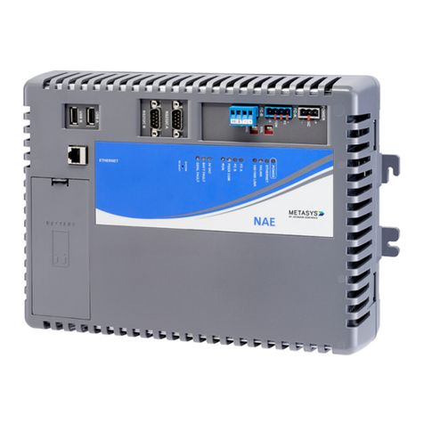
Table of Contents CK722 Network Utility Tool
vi 24-10239-30 Rev. D
This document contains confidential and proprietary information of Johnson Controls, Inc.
© 2016 Johnson Controls, Inc.

24-10239-30 Rev. D 1-1
Chapter 1
This document contains confidential and proprietary information of Johnson Controls, Inc.
© 2016 Johnson Controls, Inc.
INTRODUCTION
The CK722 Network Utility Tool (NUT) is a troubleshooting tool that allows you to restore
functionality to the CK722 network controller in the event of device failure, and upgrade the
controller’s operating system, by deleting the data from the unit and re-installing the
controller’s operating system (OS) and firmware. Once you re-install the firmware and OS,
the controller’s configuration settings will be re-initialized with the factory default settings.
Downloading the CK722 object database from the P2000AE SCT returns the controller’s
settings to their desired configuration.
This document describes how to use the Network Utility Tool (NUT) to install the CK722
controller’s OS and firmware.
IMPORTANT
The Network Utility Tool should only be used on new CK722 controllers,
when the CK722 is unresponsive and requires drastic measures to get the
unit up and running, or when you need to update the controller’s operating
system. Do not use the Network Utility Tool to update the CK722 firmware
if the unit is functioning properly and does not require an operating system
update.
To update the firmware for a properly functioning controller, use the P2000
Host software’s firmware update feature. Refer to the P2000AE Software
User Manual for details.
Using the Network Utility Tool to install the CK722 OS and firmware can take 15 minutes,
plus any setup and breakdown time.
NOTES
If you remove power from the CK722 before the device has completed the
initial reboot, the CK722 may either begin a new reboot sequence or require a
new image update altogether.
The screen captures shown in this manual may differ slightly, depending on
the software version you are using.
The terms P2000 and P2000AE are used interchangeably throughout this
manual.

Introduction CK722 Network Utility Tool
1-2 24-10239-30 Rev. D
This document contains confidential and proprietary information of Johnson Controls, Inc.
© 2016 Johnson Controls, Inc.
CHAPTER SUMMARIES
Chapter 1: Introduction provides an overview of the Network Utility Tool, including
a list of the hardware and software required to use the tool.
Chapter 2: Installation describes how to use the Network Utility Tool to install the
CK722 OS and firmware.
MANUAL CONVENTIONS
The following items are used throughout this manual to indicate special circumstances,
exceptions, important points regarding the equipment or personal safety, or to emphasize a
particular point.
NOTE
Notes indicate important points or exceptions to the information provided in
the main text.
IMPORTANT
Important messages remind you that certain actions, if not performed
exactly as stated, may cause damage to equipment or make your system
non-operational.
KEY TERMS
CK722 Disk Image – A CK722 disk image is a collection of all the software files needed for the
installation of the controller’s OS and firmware.
Network Utility Tool (NUT) – The Network Utility Tool is a software utility used to reload the
disk image into a CK722 controller.
SYSTEM REQUIREMENTS
The CK722 disk image must be installed on a standalone computer networked with the
CK722 controller (see Figure 2-1 on page 2-2). The following hardware and software are
required to install the CK722 disk image:
Computer running Microsoft® Windows Server® 2003, Windows XP®
Professional, or Windows® 2000 Professional

CK722 Network Utility Tool Introduction
24-10239-30 Rev. D 1-3
This document contains confidential and proprietary information of Johnson Controls, Inc.
© 2016 Johnson Controls, Inc.
An external power adapter to an AC power source for the computer running the
Network Utility Tool. We do not recommend running the Network Utility Tool on a
computer running on battery power. If the low battery message appears, you cannot
see it, because it appears behind the Network Utility Tool screen.
IMPORTANT
Do not run the CK722 Network Utility Tool on a P2000 server or
workstation, as this may cause a network conflict with the Dynamic Host
Configuration Protocol (DHCP) server.
Two (2) 10/100Base-T CAT5 Ethernet straight-through cables – Black Box
EVNSL80-0020 (grey cable), EVNSL82-0020 (green cable), or equivalent. Do not
use cross-over cables.
One (1) FS10x 10/100 Netgear® switch – for example, FS105 Netgear 5 Port
10/100 or one (1) W-Linx 5-port 10/100 Mini Hub (USB) (part number
SW-005CM-X) connected to the computer that will run the Network Utility Tool.
P2000AE Version 4.1 Complete Installation Software DVD
Java® Runtime Environment (JRE) Version 1.5.0_04 (see “Java Technology
Requirements”)
Java Technology Requirements
To use the Network Utility Tool, you must have the Java Runtime Environment
(JRE) Version 1.5.0_04 installed on your computer. The Network Utility Tool
installation program installs the correct version of the JRE for you if it is not present
on your computer.
Alternatively, before Network Utility Tool installation, you can download the Java 2
Runtime Environment (JRE) Version 1.5.0_04 at this site:
http://cgproducts.johnsoncontrols.com/jre/jre-1_5_0_04-windows-i586-p.exe
NOTE
If you are using Windows Server 2003 OS with the Enhanced Security
Configuration, and this site has not been added as a trusted site in Internet
Explorer, the browser blocks the JRE download. If you trust this site, add
http://cgproducts.johnsoncontrols.com/ to the list of Internet Explorer
trusted sites before attempting to download the JRE.

Introduction CK722 Network Utility Tool
1-4 24-10239-30 Rev. D
This document contains confidential and proprietary information of Johnson Controls, Inc.
© 2016 Johnson Controls, Inc.
To verify that the 1.5.0_04 JRE is installed on your computer:
1. On the Control Panel, double-click the Java Control Panel Icon.
2. Select the Java tab.
3. In the Java Runtime Environment Settings section, click View. The Java
Runtime Settings dialog box appears.
4. Verify the version 1.5.0_04 appears as one of the versions in the Java
Runtime Settings box.
5. Close all open windows.
NOTE
You may have multiple versions of the JRE on your computer, but you
must have the same version of the JRE on your computer as that of the
site you need to access. If you have other JRE versions you are not using,
uninstall them.
Media Access Control (MAC) Address
Know the Media Access Control (MAC) address of the CK722 that will receive the
latest OS and firmware. Find this information in one of the following ways:
The sticker on the side of the CK722’s enclosure contains the MAC address.
Use Tera Term Pro or other terminal emulation program on the computer that
will run the Network Utility Tool. Shortly after receiving power
(approximately 3 minutes), the CK722 MAC address appears on the
computer screen. See the “Terminal Emulation Software (Optional)” section
for more information.

CK722 Network Utility Tool Introduction
24-10239-30 Rev. D 1-5
This document contains confidential and proprietary information of Johnson Controls, Inc.
© 2016 Johnson Controls, Inc.
Terminal Emulation Software (Optional)
As an option, CK722 communication data can be viewed using the following
hardware and software:
RS232 Null Modem Cable (DB9F/F) – Black Box EYN257T-0015-FF or
equivalent (see “Null Modem Cable” on page 1-7 for more information)
Terminal Emulation Software (Tera Term Pro Preferred) – To use the free
Tera Term Pro software, download and install the latest version from the
following site:
http://hp.vector.co.jp/authors/VA002416/teraterm.html
NOTE
The Tera Term Pro terminal emulation software was used in the
development of this document. Use of other terminal emulation programs
may differ.
For more information on configuring Tera Term Pro, see:
“Null Modem Cable” on page 1-7
“Connecting the Computer to the CK722” on page 2-1
“Configuring Tera Term Pro (Optional)” on page 2-5
Host Name Restrictions
The Host Name field on the Update Target dialog box (see page 2-8) is used to reset
the CK722 Item Reference name at the end of the update process. The Network
Utility Tool places restrictions on the Host Name of any CK722 controller. This
change is in response to Microsoft Corporation’s enforcement of an Information
Technology (IT) naming standard for the operating system used in affected engines.
Names must start with a letter, end with either a number or letter, and may contain
dashes only in the interior of the name.
If a CK722 controller has an existing name that violates the standards, and you
choose not to use the Update Target dialog box to rename the CK722 to a name that
follows the standards, the CK722 is given the name NAE<MAC address> during
the update. You then can rename the CK722 via the database download process after
the update. Refer to the instructions for downloading the P2000SCT archive
database to a new CK722 controller in the CK722 Commissioning Guide.
In the Update Target dialog box, if you enter a Host Name that violates the
standards, a message box appears warning you of the violation, and you must enter a
different name.

Introduction CK722 Network Utility Tool
1-6 24-10239-30 Rev. D
This document contains confidential and proprietary information of Johnson Controls, Inc.
© 2016 Johnson Controls, Inc.
Cable Wiring
Ethernet Straight-through Cable
The Ethernet straight-through cable provides a network connection from the CK722
Ethernet port to the computer’s network port via a hub or switch.
Connector 1 Pinout Connector 2 Pinout
TX = Transmit
RX = Receive
1 TX+ 1 RX+
2 TX- 2 RX-
3 RX+ 3 TX+
6 RX- 6 TX-
Make sure you use straight-through Ethernet cables. To verify that you have a
straight-through cable, use a cable tester. If you do not have a cable tester, visually
inspect the cables by holding both ends of the cable either tab up or tab down. The
order of the colors/terminations at both ends of a patch cable should be identical (see
Figure 1-1).
Figure 1-1: Straight-through Ethernet Cable

CK722 Network Utility Tool Introduction
24-10239-30 Rev. D 1-7
This document contains confidential and proprietary information of Johnson Controls, Inc.
© 2016 Johnson Controls, Inc.
Null Modem Cable
The null modem cable provides an RS-232 serial connection from the CK722
RS232C A port to the COM port of the computer running the terminal emulation
software, such as Tera Term Pro.
Connector 1 Pinout Connector 2 Pinout
TX = Transmit
RX = Receive
RTS = Request to Send
CTS = Clear to Send
SG = Signal Ground
DSR = Data Set Ready
DTR = Data Terminal Ready
3 TX 2 RX
2 RX 3 TX
7 RTS 8 CTS
8 CTS 7 RTS
5 SG 5 SG
6 DSR 4 DTR
4 DTR 6 DSR

Introduction CK722 Network Utility Tool
1-8 24-10239-30 Rev. D
This document contains confidential and proprietary information of Johnson Controls, Inc.
© 2016 Johnson Controls, Inc.

24-10239-30 Rev. D 2-1
Chapter 2
This document contains confidential and proprietary information of Johnson Controls, Inc.
© 2016 Johnson Controls, Inc.
INSTALLATION
This chapter describes how to use the Network Utility Tool to install the CK722 controller’s
operating system and firmware.
INSTALLATION OVERVIEW
The installation process consists of the following steps:
Preparing the Computer (see page 2-1)
Configuring Tera Term Pro (Optional) (see page 2-5)
Installing the CK722 OS and Firmware (see page 2-6)
Downloading the P2000SCT archive database to each CK722 controller that has
been updated with the Network Utility Tool (see page 2-12)
Before continuing, verify you have met the requirements in the “System Requirements”
section, starting on page 1-2.
PREPARING THE COMPUTER
This section provides instructions on preparing your computer to install the CK722 disk
image files.
Connecting the Computer to the CK722
This section provides instructions on connecting a computer to the CK722 to run the
Network Utility Tool.
To connect the computer to the CK722 controller:
1. Disconnect the CK722 from the Ethernet network, and connect a switch/hub
with two straight-through Ethernet cables between the Ethernet port of the
CK722 and your computer. See Figure 2-1.

Installation CK722 Network Utility Tool
2-2 24-10239-30 Rev. D
This document contains confidential and proprietary information of Johnson Controls, Inc.
© 2016 Johnson Controls, Inc.
2. (Optional) Connect the RS232 Null Modem Cable to the computer’s
COM 1 or COM 2 port. Connect the other end of the cable to the CK722’s
RS232C A port. This connection enables you to use your computer as a
CK722 terminal to monitor the software installation process.
3. Verify that the 10 Link or 100 Link LED on the CK722 and switch/hub are
lit to confirm connectivity between the computer and the CK722 via the
switch/hub.
Computer
CK722 Controller
RS232 Null Modem Cable
(DB9F/F)* (Optional)
COM 1 or 2**
Ethernet
RS232C A
Serial Port
Ethernet Port
10/100Base-T CAT5 Ethernet
Straight-through Cable*
Power
* Maximum Distance: 15 m (50 ft.)
** Baud Rate: 115200
Hub/Switch
10/100Base-T CAT5 Ethernet
Straight-through Cable*
Figure 2-1: Computer to CK722 Controller Connections
Verifying Network Settings
Verify the computer has a valid Internet Protocol (IP) address.
To verify a valid IP address:
1. On the Start menu, select Run.
2. Type cmd in the Open field.
3. Click OK.
4. At the command prompt, type ipconfig and press <Enter>.
If the computer IP address is all 0s, wait several minutes. Repeat ipconfig
until the address is established.

CK722 Network Utility Tool Installation
24-10239-30 Rev. D 2-3
This document contains confidential and proprietary information of Johnson Controls, Inc.
© 2016 Johnson Controls, Inc.
In addition, verify that the Local Area Connection (LAN) for the Ethernet
connection to the CK722 is enabled and all other network connections (including
wireless connections) are disabled.
To verify the LAN Ethernet connection to the CK722 is enabled:
1. On the Control Panel, select Network Connections or Network and
Dialup Connections.
2. Verify that the Local Area Connection for the Ethernet connection to the
CK722 is enabled. All other connections should be Disabled or
Disconnected.
To disable or enable a connection, right-click the connection and choose
from the menu.
Installing the Network Utility Tool
To install the Network Utility Tool:
1. Insert the P2000AE Version 4.1 Complete Installation Software DVD.
2. Open Windows® Explorer and access the following directory:
<CD/DVD Drive>:\FirmwareResourceCD\Tools\NUT
3. Double-click Setup.exe.
If you have a previous version of the Network Utility Tool installed, a
Question dialog box appears. Click Ye s.
NOTE
Previous versions of the Network Utility Tool remain visible in the
Add/Remove Programs list but can be removed at any time. Only the files
from the newest version exist on the hard disk of your computer, and the
presence of the previous versions in the Add/Remove program list does
not affect the performance of the newest version.
The Network Utility Tool Installation wizard appears.

Installation CK722 Network Utility Tool
2-4 24-10239-30 Rev. D
This document contains confidential and proprietary information of Johnson Controls, Inc.
© 2016 Johnson Controls, Inc.
4. Click Next.
The Ready to Install the Program screen appears.
5. Click Install.
The Installation Complete screen appears when the Network Utility Tool is
installed successfully in the C:\NAEUpdateTool folder on the computer.
6. Click Finish.
Table of contents
Other Johnson Controls Network Hardware manuals

Johnson Controls
Johnson Controls NIE55 Series User manual

Johnson Controls
Johnson Controls NAE55 Series User manual

Johnson Controls
Johnson Controls IQ WIFI User manual

Johnson Controls
Johnson Controls S300 Series Manual

Johnson Controls
Johnson Controls XP-910x User manual

Johnson Controls
Johnson Controls D Series User manual

Johnson Controls
Johnson Controls EasyIO FW Series User manual

Johnson Controls
Johnson Controls Tyco exacqVision 2UA User manual

Johnson Controls
Johnson Controls Facility Explorer Service manual

Johnson Controls
Johnson Controls Metasys NAE55 User manual