Johnson Matrix Retail TF30 User manual

JOHNS
O
A
Kyl
J
o
O
N
Issu
e
Re
v
d
a
A
pproval
l
e Schweit
z
o
hns
o
e
date 20
1
v
ision
a
te
20
1
z
e
r
o
n In
d
TF3
1
6-09-27
1
6-12-26
ustri
e
0/TF
5
Ser
v
Editio
n
Edition ti
Revie
w
e
s (S
h
5
0/T5
0
v
ice
M
n
01
m
e01
w
h
ang
h
0
-02/T
7
M
anua
l
Doc N
o
Page
h
ai)
C
7
0-02
l
o
. SM-T
M
Editor
A
lex Tan
g
C
o., L
t
1
M
-AF-003
26
g
t
d

M
M
M
atrix
R
M
atrix
R
R
etail T
R
etail T
5
F30
5
0-02
Produ
u
ct Bro
Mat
r
Matri
x
wse
r
ix Ret
a
x
Retail
a
il TF50
T70-0
2
2
2
2

3
Contents
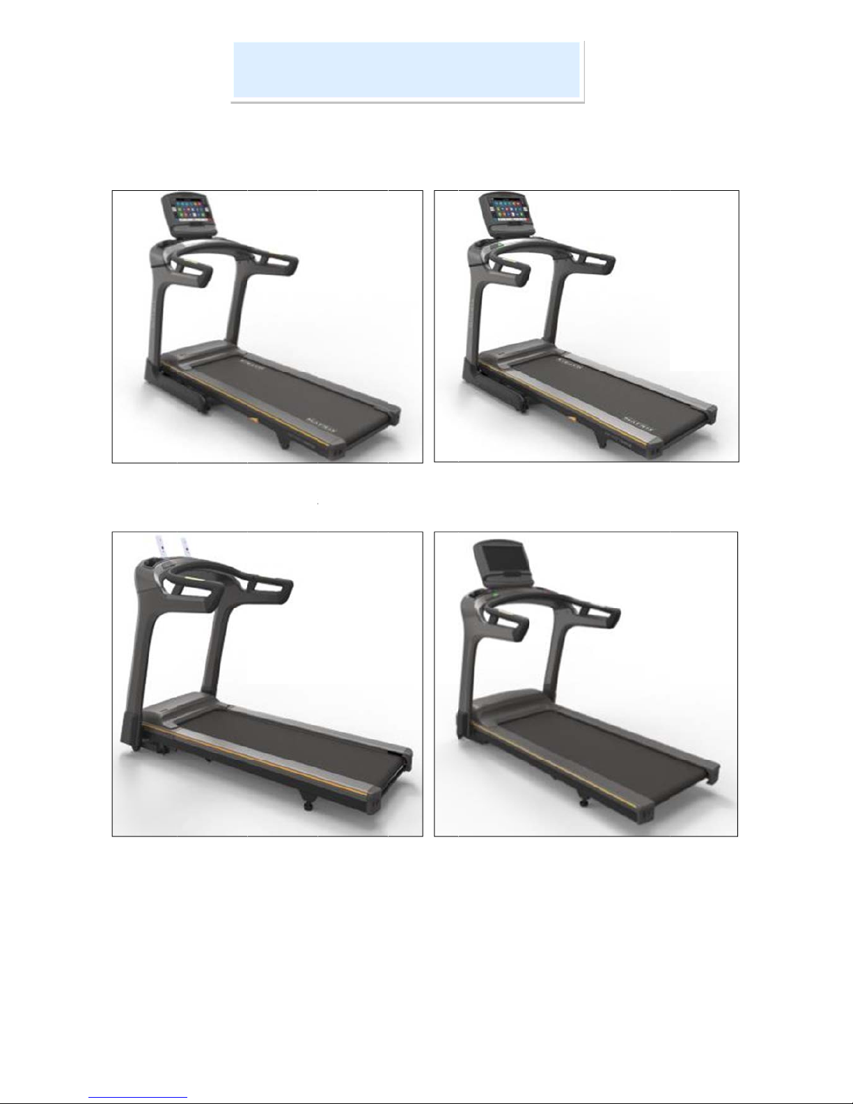
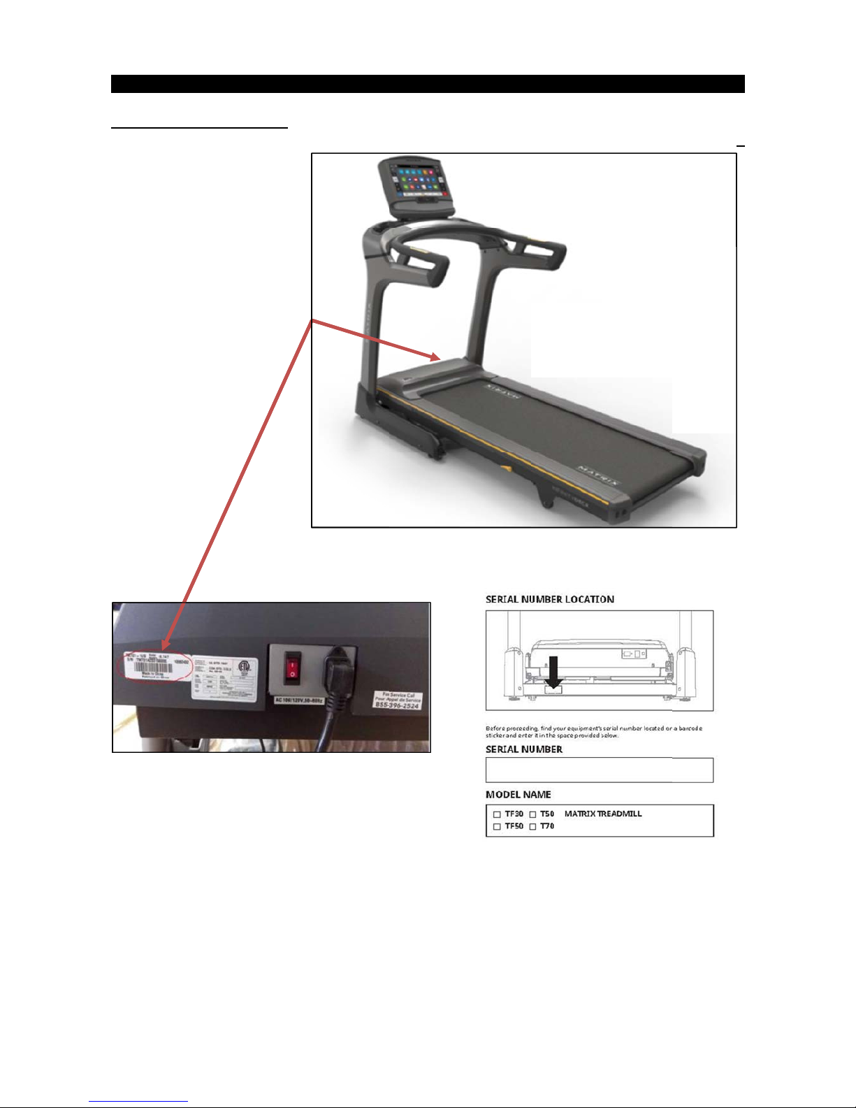
CHAPTER 1: SERIAL NUMBER LOCATION ................................................................................................... 4
CHAPTER 2: TROUBLESHOTING
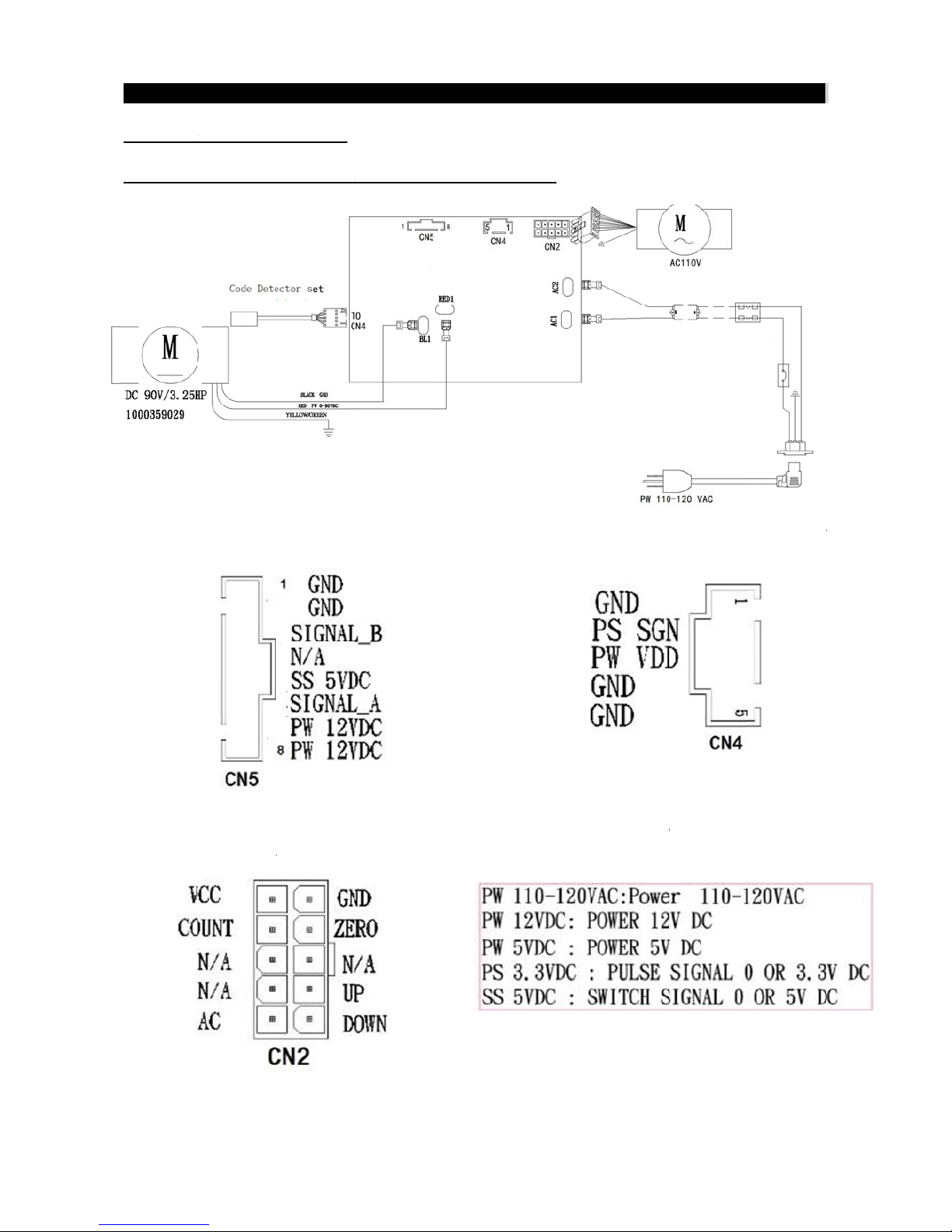
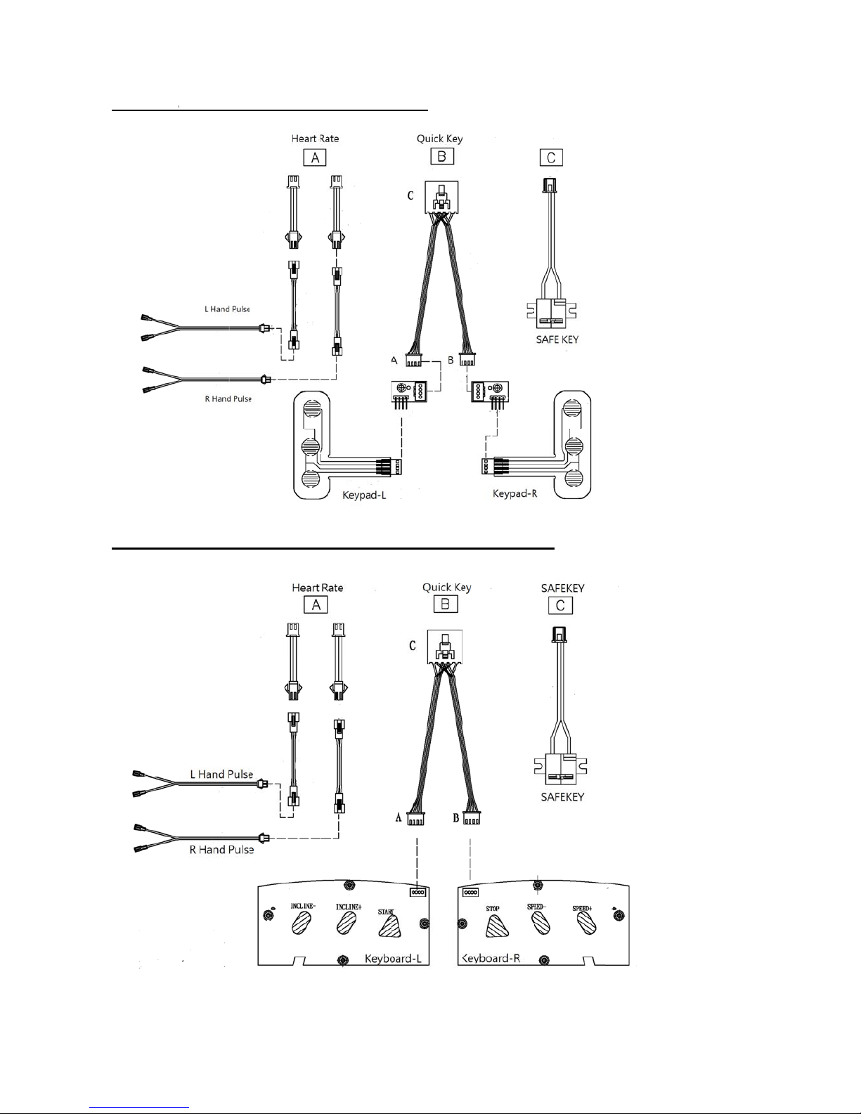
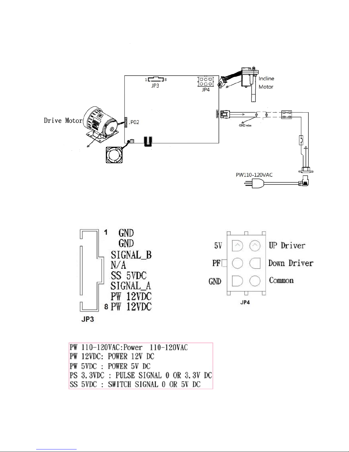
2.1 Electrical Diagram…………………………………………………………………………………………………5
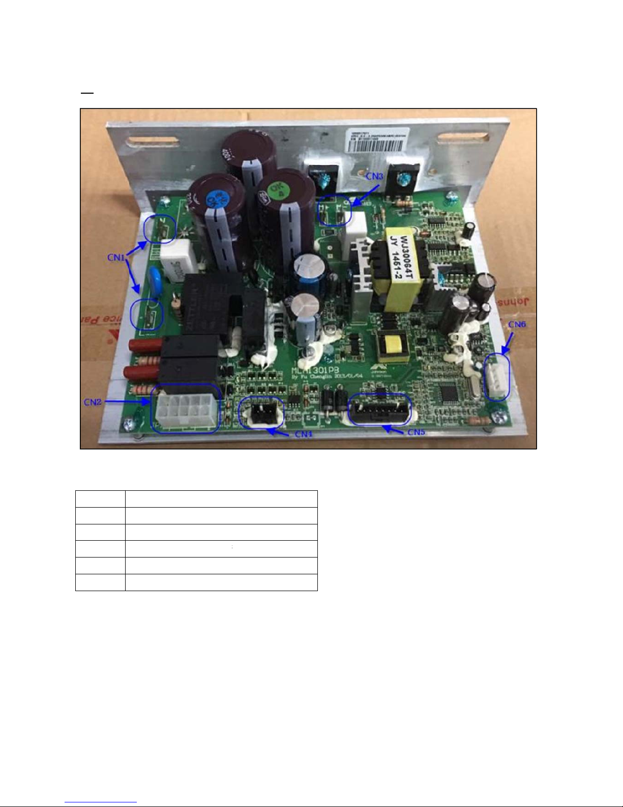
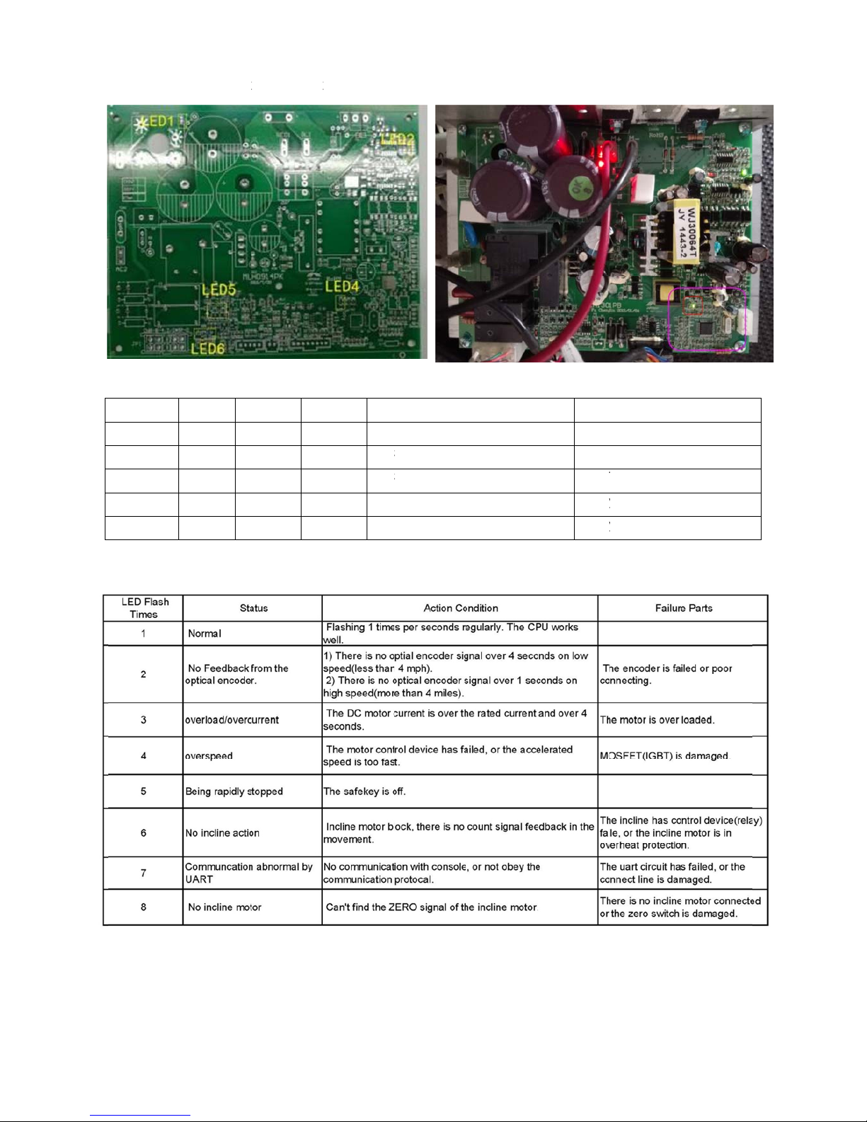
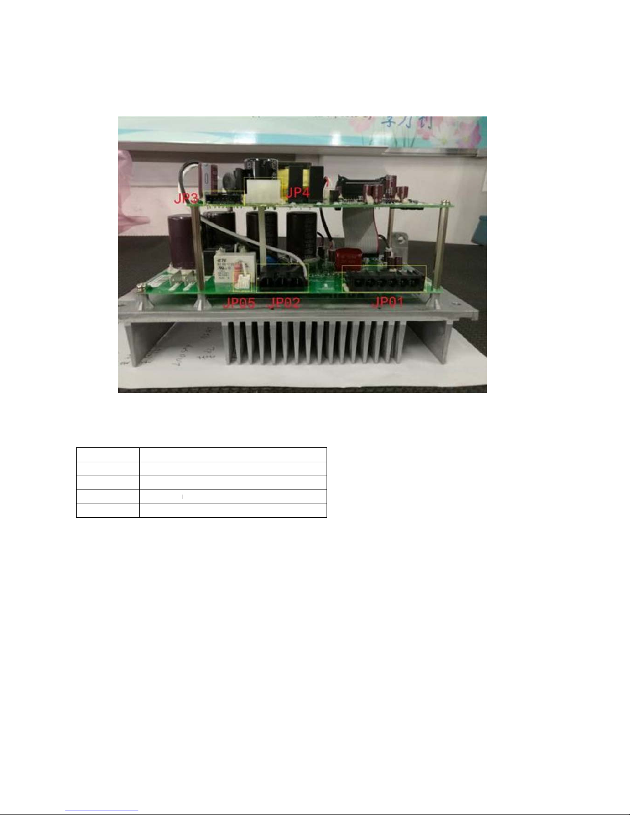
2.2 MCB instructions……………………………………….……………………………….…………………….......8
2.3.1 Troubleshooting - No Function For Safety Key ................................................................................... 12
2.3.2 Troubleshooting - No Response For Machine When Pressing Start……………………………………..13
2.3.3 Troubleshooting - Incline Motor Issues ................................................................................................. 14
2.3.4 Troubleshooting - Noise Issues ............................................................................................................ 15
2.3.5 Troubleshooting - Heart Rate Function Issues ..................................................................................... 16
CHAPTER 3: PART REPLACEMENT GUIDE
3.1 Motor Replacement .................................................................................................................................. 17
3.2 Side Rail Replacement ............................................................................................................................ 19
3.3 Rear Roller Replacement ......................................................................................................................... 20
3.4 Running Deck Replacement .................................................................................................................... 21
3.5 Front Roller Replacement ........................................................................................................................ 22
3.6 Running Belt Replacement ...................................................................................................................... 23
3.7 Motor Control Board (MCB) Replacement ............................................................................................... 24
3.8 Incline Motor Replacement ...................................................................................................................... 25
3.9 Console Replacement..............................................................................................................................26

Serial N
u
u
mber Lo
c
C
H
c
ation
H
APTER 1
: Serial N
u
u
mber Loc
a
a
tion
4
4

2.1 ELEC
1. MCB E
Fig-1 the
M
Fig-
3
C
TRICAL
D
LECTRIC
A
M
CB TO CO
3
The MCB
T
PIN
L
D
IAGRAM
A
L DIAGR
A
NSOLE PIN
T
O INCLINE
L
AYOUT
CH
A
PTE
R
A
M---TF3
0
LAYOUT
MOTOR
R
2: Trou
0
/
TF50/TF
Fig
-
bleshooti
n
50-02
-
2 the MC
B
TH
g
B
TO SPEE
D
E PIN VOLT
A
D
SENSOR
P
TA
GE INFO
R
5
P
IN LAYOU
T
R
MATION
5
T

CONSO
L
2. CONS
O
L
E ELECT
R
O
LE ELE
C
R
ICAL DI
A
C
TRICAL
D
A
GRAM---
T
D
IAGRAM
T
F30
---TF50/T
5
5
0-02/T70
-
-
02
6
6

3. MCB E
Fig-1 t
h
LECTRIC
A
h
e MCB TO
C
Fig-3 Th
e
A
L DIAGR
A
C
ONSOLE
P
e
PIN VOLT
A
A
M---T70
-
P
IN LAYOU
T
A
GE INFOR
M
-
02
T
M
ATION
Fi
g
g
-1 MCB TO INCLINE PI
7
N LAYOUT
7

2.3. MCB
1. TF30/
T
CN1
CN2
CN3
CN4
CN5
CN6
instructio
n
T
F50/TF50
-
Power Line
Incline mot
o
Drive motor
Speed sens
Console ca
b
Software b
u
n
s
-
02
in terminals
o
r power cab
cable termi
n
or cable so
c
b
le socket
u
rning cable
s
le socket
n
als
c
ket
s
ocket
Fig -1
8
8

2. MCB L
Table1-M
C
LED No
LED1
LED2
LED4
LED5
LED6
Table2-M
C
ED’s func
t
C
B LED FU
Color A
Red li
g
Green li
g
Green fl
a
Green li
g
Green li
g
C
U STATU
S
t
ion indica
t
NCTION
ctive In
a
g
ht on lig
h
g
ht on lig
h
a
sh
-
g
ht on lig
h
g
ht on lig
h
S
(LED4)
t
or (TF30/
T
a
ctive Fu
n
h
t off Dri
v
h
t off MC
-
----- MC
h
t off Incl
h
t off Incl
T
F50/TF5
0
n
ction
v
er Motor ac
t
C
B Power ind
C
U status se
e
ine down in
d
ine up indic
a
0
-02)
t
ive
icator
e
Table2
d
icator
a
tor
Sym
p
Not
v
Not
v
See
T
Rela
y
Rela
y
ptom
v
oltage to dr
v
oltage outp
u
Table2
y not active
y not active
9
i
ve motor
u
t
MCB fail
MCB fail.
9

3. MCB
C
JP01
JP02
JP3
JP4
JP05
C
IRCUIT B
O
Drive m
o
Power Li
Console
Incline
m
Fan cabl
e
FIF
O
ARD IN
S
o
tor cable so
c
ne in socket
set cable so
m
otor cable s
o
e
socket
S
TRUCTI
O
Fig-1
c
ke
t
c
ke
t
o
cke
t
O
NS (T70-
0
0
2)
1
0
0

4. MCB L
Table1-MC
B
T Table 2-
M
ED’s funct
B
LED FUN
C
M
CU STATU
ion indica
t
C
TION
S (LED6)
or -TF70-
0
0
2 (Fig1&
F
F
ig2)
11

12
CHAPTER 2: Troubleshooting
2.3.1. TROUBLESHOOTING – NO FUNCTION FOR SAFETY KEY
SOLUTION:
a.Check if the safety key is totally inserted into the console.
- If not, remove and insert again.
b.Check if the safety key is oxidized or damaged.
- If yes, try cleaning it or replace it.
c. If the safety key is not damaged, check the alignment of the reed switch (safety key sensor)
and wire connection in the console.

13
CHAPTER 2: Troubleshooting
2.3.2 TROUBLESHOOTING – NO RESPONSE FOR MACHINE When Pressing Start
SOLUTION:
a. Check if the console beeps when all keys are pressed. If no, replace the keypads
b. Enter Engineering Mode, and scroll to ENG 1 (Hardware Test). Press the “ENTER” key first and
then the key “START”.
- When press the key “SPEED + / -“, if the data on windows “TIME” & “DISTANCE” change, the
Console is ok. If not, replace the UCB.
c. Verify the motor or running belt spins freely - remove any obstructions from under the running belt
or motor compartment that may cause a block in movement.
d. Check the console cable connection. Also, console cable continuity can be tested with Ohms
on each wire of the cable.
e. Test the drive motor.
1. 30/50 series short test - Disconnect power from the unit. Remove the motor cover. Remove
the red and black motor wires from the MCB. Using a jumper wire (or metal paper clip), make
the connection between the red and black leads of the motor. Without the jumper wire, the running
belt will move freely with little to no resistance. With the jumper wire in place there will be a great
amount of resistance when trying to push the running belt. If there is resistance, the motor is good.
30/50 series battery test - Disconnect power from the unit. Remove the motor cover. Remove the
red and black motor wires from the MCB. Using a DC battery from a cordless drill or other device,
touch the red on the positive lead of the battery and the black to the negative lead. If the motor
runs, the motor is good.
2. 70 series windings test - Disconnect power from the unit. Remove the motor cover. Remove the
motor connection from the MCB. With an Ohm meter test the resistance level between the
motors three phases; pin 1 and pin 2, pin 1 and pin 3, then pin 2 and pin 3. If all three resistance
levels are the same, the motor is good. If one or more are different, replace the motor.
f. If the drive motor is ok. Then,
- Check the connection of the speed sensor (encoder disk group) at the MCB.
- Remove the speed sensor from the motor and clean it, then re-test.
- If the speed sensor is clean and has a good connection but still will not operate, replace the speed
sensor.
- Replace the MCB as the last step if machine does still not run after to take above actions.

14
CHAPTER 2: Troubleshooting
2.3.4 TROUBLESHOOTING - INCLINE MOTOR ISSUES
SOLUTION:
a. While using the machine press the "INCLINE" keys, the console should beep and display incline
change, if no, replace the key pad.
b. Enter Engineering Mode, and scroll to ENG 1 (Hardware Test). Press the “ENTER” key
first and then the “START” key.
c. Press the “INCLINE ▲/▼” key.
If can hear clicks from two relays and LED light (see table 2.2.2 and 2.2.4) at the MCB, the MCB is
ok. Then check the connection of the elevation motor at the MCB. First try to unplug and re-plug
connection . If this does not resolve the issue, replace the elevation motor.
If there is no clicks from these two relays or LED light, MCB is defective and replace the MCB.

15
CHAPTER 2: Troubleshooting
2.3.4 TROUBLESHOOTING - NOISE ISSUES
SOLUTION:
a.Thumping noise twice per rotation on new machine.
This noise is from the roller or running belt.
- If this is a new unit, some noise is normal as the running belt forms around the rollers.
- Check that the belt is centered and tensioned correctly.
- Remove and clean the rollers if needed.
- Replace the rollers or running belt as needed.
b. High pitched “bell-like” sound from under the motor cover.
This sound is likely a moving component.
- Remove the motor cover and check the drive belt for alignment and make sure it is not slipping or is
frayed / cut in any way. Replace the drive belt if needed.
- Make sure the optic disk on the motor is not rubbing the speed sensor.
- Turn the motor by hand to see if motor bearings are rubbing. Replace the motor if needed.
- Check the front and rear rollers, replace if needed.
c. Rubbing / grinding noise.
This sound is likely caused by the optic disk.
- Check that the optic disk is tight on the motor and not rubbing the speed sensor.
d. Banging or clunking sound/slapping / squeaking sound with each footstep.
The sound is likely due to the unit not being level.
- Check that all levelers are touching the ground.
- Move the treadmill to another flat surface.
-This sound is from the running deck / belt.
- Remove the side rails and tighten the deck bolts and elastomers.
- Check the deck shocks for disintegration or crumbling. Replace if needed.
e. Rubbing sound underneath the treadmill.
This sound is likely due to the air shock.
- Lubricate or replace the air shock as needed.
f. Squeaking / grinding noise when using elevation.
This sound is likely from the incline motor.
- Check that the incline motor and incline rack connection points to the main frame are tight.
Replace Teflon washers on the frame as needed.
- Lubricate the incline motor worm screw and connection points with grease.
- Replace the incline motor.

16
CHAPTER 2: Troubleshooting
2.3.5 TROUBLESHOOTING- HEART RATE FUNCTION ISSUE
SOLUTION:
a.Telemetric heart rate:
1. Re-center the chest strap below the user's pectoral muscle and check again.
2. Replace the battery in the chest strap
.
b.Heart rate grip:
1. Wet the user's hand, and then reestablish contact with the HR grip.
2. Replace new HR grip if console can display proper HR rate.
With a multi-meter set for DC voltage, place one terminal on each of the HR grip plates. The HR
Grip should give a voltage reading of between 0.5 and 2.0VDC. If the voltage is not between 0.5
And 2.0VDC, remove the screws holding the HR grip together and check the connection of the
HR grip wiring.
3. Check a-d. If still cannot work, Suggest install new console.

3.1 MOT
O
1.TF30/T
F
1) Discon
n
2) Remov
3) The co
v
4) Fig-3 &
F
5) Unplug t
h
6) Remove
outer ed
g
7) Remove
8) Reverse
pulley. In
s
the drive
10) Test at
v
O
R REPL
A
F
50
n
ect power
c
e the 2 scre
w
v
er is secur
e
F
ig-4 shows
t
h
e motor co
n
the drive be
g
e of the tre
a
the four mo
t
steps to ins
t
s
tall belt on
d
belt, roll the
v
arious spe
e
C
H
A
CEMEN
T
c
ord.
w
s holding t
h
e
d to the fra
m
t
he motor M
C
n
nector from
lt by spinnin
g
a
dmill.
t
or bolts and
t
all motor.
W
d
rive motor
p
belt on. Co
n
e
ds.
H
APTER
3
T
h
e motor co
v
m
e with Velc
r
Fig-1
C
B area wit
h
Fig-3
LCB, speed
g
the flywhe
e
remove mo
t
hen installin
g
p
ulley. Then
n
tinue to wal
k
3
: Part R
e
v
er to the fra
m
r
o so you wil
h
the motor
c
d
sensor, cut
e
l (or runnin
g
t
or.
g
Flexonic d
by rotating
t
k
belt on unt
i
e
placeme
n
m
e (Fig-1)
l have to pul
c
over remov
e
any wire tie
s
g
belt) and
w
rive belt, sta
he front roll
e
i
l centered o
n
t Guide
l up with so
m
e
d. (Fig-3 &
F
s
as needed
.
w
alking the d
r
r
t with belt o
n
e
r pulley whil
n
both pulle
y
m
e force (Fi
g
F
ig-4)
.
r
ive belt off t
o
n inside of f
r
e applying
p
y
s.
1
7
g
-2)
Fig-2
Fig-4
o
ward the
r
ont roller
p
ressure on
7

2. MOTO
R
1) Discon
n
2) Remov
e
3) Note.
T
3) Disconn
e
4) Remov
e
5) Remov
e
6) Revers
e
Note: wh
e
rol
7) Test at v
a
R
REPLA
C
n
ect power
c
e
the 2 scre
w
T
he cover is
Fig
-
e
ct motor wi
r
Fig
-
e
spring fro
m
e
4 bolts se
c
e
steps to in
s
e
n installing
ler pulley.
a
rious spee
d
C
EMENT
(
c
ord.
w
s holding t
h
secured to
t
-
1
r
es and grou
-
3
m
the belt te
n
c
uring motor
s
tall motor.
R
the drive be
l
d
s.
(
TF70-02)
h
e motor co
v
t
he frame wi
t
nds, cut any
n
sioner. R
e
and remove
R
eplace any
l
t, rotate by
h
v
er to the fra
m
t
h Velcro so
wire ties as
e
move drive
b
motor from
wire ties th
a
h
and severa
l
m
e (Fig-1).
you will hav
e
needed.
b
elt from m
o
drive comp
a
a
t were remo
l
rotations,
m
e
to pull up
w
tor pulley.
rtment.
v
ed.
m
ake sure it i
s
w
ith some fo
r
s aligned wi
t
1
8
r
ce (Fig-2)
Fig-2
Fig-4
t
h the front
8

3.2 SIDE
RAIL RE
P
C
H
P
LACEME
H
APTER
3
NT
3
: Part R
e
e
placeme
n
n
t Guide
1
9
9

3.3 REA
R
1) Remov
e
2) Remov
e
3) Replac
e
4) Revers
e
N
ote
1. be s
u
2. Over
3.
A
lwa
y
4. Final
to st
o
5. For t
h
R
ROLLE
R
e
side rail in
e
rear roller
e
new rear r
o
e
step 2 to s
t
Fig-1
u
re to set th
e
r
or under te
n
ys bring ten
s
steps of ten
o
p the belt
w
h
ee ADJUS
T
C
H
R
REPLA
C
section 3.2
o
ller and tig
h
t
ep 1
e
correct run
n
n
sion can re
s
s
ion up eve
n
sioning are
w
w
ith you r fee
t
T
INNG Tie
R
H
APTER
3
C
EMENT
h
tness bolts
(
n
ing belt ten
s
s
ult in dama
g
ly from the l
e
w
hen the ru
n
t
using an a
b
R
UNNNING
B
3
: Part R
e
(
Fig-1)
s
ion after re
p
g
e or injury.
e
ft to right t
e
n
ning belt jus
b
rupt stop at
B
ELTT refer
e
e
placeme
n
p
lacing the
b
e
nsioning bol
t stoops slip
p
a walking s
p
e
nce section
1 bolt
n
t Guide
b
elt.
t
s using sm
a
p
ing and slo
w
p
eed.
3.6 note 2
each side
a
ll adjustme
n
w
s the moto
r
2
0
n
ts.
r
when tryin
g
0
g
This manual suits for next models
3
Table of contents
Other Johnson Fitness Equipment manuals

Johnson
Johnson AF5.5AE User manual

Johnson
Johnson T7000 PRO User manual

Johnson
Johnson W7000 User manual

Johnson
Johnson Stepper S8000 User manual

Johnson
Johnson S7000 User manual

Johnson
Johnson AB Trainer User manual

Johnson
Johnson T7xe User manual

Johnson
Johnson Magnum Series User manual

Johnson
Johnson Matrix Retail A30 User manual