jotron Tron 40VDR AIS User manual

Tron 40VDR AIS
Float-free EPIRB with VDR storage
User manual

1Manual operation and activation
Use only in emergency!
raft, or under a
cover or canopy. Do NOT tie the lanyard to the ship in distress, as this will
prevent the unit from functioning if the ship sinks.
1. Remove the locking pin from the front cover.
2. Remove the front cover.
3. Take the EPIRB out of the bracket.
4. Pull the red tab.
5. Push the switch to activate the EPIRB.
6. Unclip and release the lanyard.
7. Tie the lanyard to yourself or to the life raft.
The strobe light will start flashing indicating that the EPIRB is operating.
If possible, keep the EPIRB in an open area, away from any metal objects
(ship construction etc.) that may limit the satellite coverage. Transmissions
can be stopped by taking the EPIRB out of water and turning the switch to
middle position.

jotron.com Page 3 of 56
Table of Contents
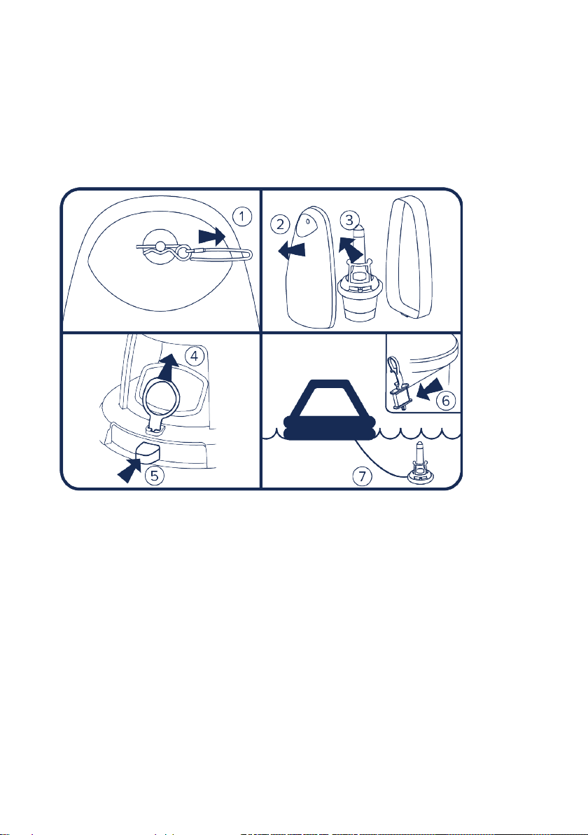
1Manual operation and activation ................................................ 2
2General ........................................................................................ 5
3Operating instructions................................................................. 6
3.1 Manual activation ...............................................................6
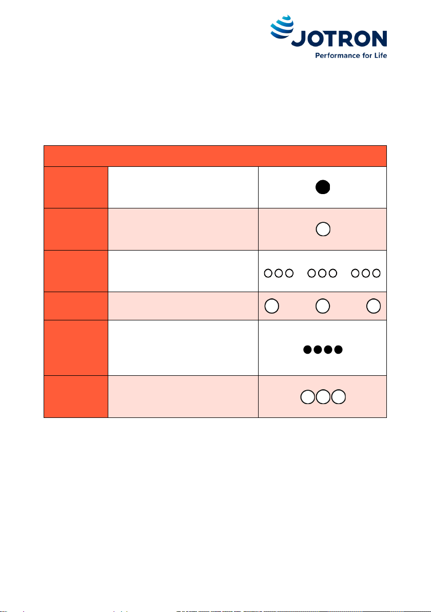
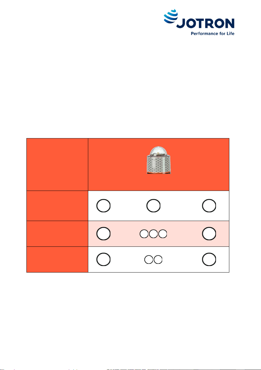
3.2 Indicator descriptions .........................................................7
3.3 Automatic activation.........................................................10
3.4 Operating scenarios ..........................................................11
3.5 Self-test .............................................................................14
3.6 Deactivation of the EPIRB .................................................21
3.7 False alerts ........................................................................22
4Product description ................................................................... 23
4.1 Tron 40VDR AIS EPIRB.......................................................24
4.2 FB-40 or FBH-40 Bracket...................................................30
4.3 VDR storage module .........................................................31
4.4 Return Link Service (RLS) ..................................................31
5Registration, Installation and mounting .................................... 32
5.1 Registration of the EPIRB..................................................32
5.2 Change of ownership........................................................33
5.3 Installation.........................................................................33
5.4 Bracket installation and mounting ...................................33
5.5 Mounting the EPIRB in the bracket ..................................35
5.6 Fitting the front cover.......................................................37
6Testing and maintenance .......................................................... 37
6.1 Every month......................................................................37
6.2 Every 3 months .................................................................38
6.3 Every 12 months ...............................................................38
6.4 Every 2nd year....................................................................39
6.5 Every 4 or 5 years..............................................................39
6.6 Every 10 years ...................................................................39
6.7 Hydrostatic release unit (HRU) replacement ...................39
6.8 Shore based maintenance (SBM) .....................................41
6.9 Battery expiry date............................................................42

jotron.com Page 4 of 56
7Technical information................................................................ 43
7.1 General..............................................................................43
7.2 Strobe light........................................................................43
7.3 Cospas-Sarsat transmitter ................................................44
7.4 GNSS receiver....................................................................44
7.5 Homing transmitter ..........................................................44
7.6 AIS transmitter ..................................................................45
7.7 Brackets.............................................................................45
7.8 Battery information ..........................................................46
7.9 Cospas-Sarsat system .......................................................47
7.10 AIS system .........................................................................49
7.11 121.5 MHz homing signal .................................................50
7.12 Position receiver (GNSS) ...................................................50
7.13 RLS system.........................................................................51
8Spare parts, warranty and disposal ........................................... 52
8.1 Accessories and spare parts .............................................52
8.2Counterfeit spare parts.....................................................52
8.3 Warranty ...........................................................................52
8.4 Service ...............................................................................53
8.5 Disposal .............................................................................53
9Abbrevations and definitions..................................................... 54
10 Ammendment records .............................................................. 55

jotron.com Page 5 of 56
2General
Jotron manufactures safety products designed for search and rescue of
human lives and property. For this product to be effective according to the
design parameters, it is imperative that it is handled, maintained, serviced
and stowed in accordance with this manual.
All information contained within this manual has been verified and is to
Jotron’s knowledge correct. Jotron reserves the right to make changes to
any product(s) or module(s) described herein to improve design, function
or reliability without further notice.
Jotron is not liable and cannot be held responsible for
any injury or damages caused directly or indirectly by an
error or omission of information, incorrect or misuse,
breach of procedures or failure of any specific
component or part of this product.
jotron.com.

jotron.com Page 6 of 56
3Operating instructions
3.1 Manual activation
To activate the EPIRB follow these steps:
1. Remove pull tab
2. Push switch
Use only in emergency!

jotron.com Page 7 of 56
3.2 Indicator descriptions
The following tables describes the status of the different indicator lights
when the EPIRB is operating normally.
Indicator light descriptions
Off
The LED is off
On
The LED is on
Triple flash
The LED flashes fast in
sequences of 3 consecutive
flashes
Steady
flash
The LED flashes periodically
with a long flash
Multiple
short off
periods
The LED is turned off for short
periods, creating a blink
effect. (Negative blink,
occulting blink)
Multiple
flashes
The LED flashes multiple times

jotron.com Page 8 of 56
3.2.1 Strobe light
When the EPIRB is activated the strobe light will start flashing steadily with
approximately 21 flashes per minute.
The first 406 MHz signal will be transmitted 60 seconds after activation.
This is indicated with a triple flash.
After approximately 4.5 minutes the first AIS signal is transmitted. This is
indicated with a double flash. At the same time the 121.5 MHz homing
signal will start transmitting.
Strobe light
EPIRB active
Steady flashes
406 MHz signal
transmitted
Triple flashes
AIS signal
transmitted
Double flashes

jotron.com Page 9 of 56
3.2.2 Position indicator (GNSS)
Position indicator
Waiting for position
Triple flashes
Position achieved
Steady flashes
3.2.3 RLS indicator (if enabled)
Confirmation that the distress signal has been detected and received. See
chapters 4.4 and 7.13 for more information.
RLS indicator
Waiting for RLS
Triple flashes
RLS acknowledged
Steady flashes
RLS disabled
(EPIRB is not equipped with RLS
protocol)
No light

jotron.com Page 10 of 56
3.2.4 Test indicator
The test indicator is not active during normal activation of the EPIRB.
3.3 Automatic activation
3.3.1 Float-free
If the ship is sinking, the EPIRB will be automatically released from the
bracket when it has reached a depth of 2-4 meters (6-13 feet) and start
transmitting when it has reached the surface.
The transmission will continue until the EPIRB is lifted out of the water and
dried off.
3.3.2 Water activation
The EPIRB is designed to automatically activate when deployed into water.
An internal safety function will prevent inadvertent activation caused by
moisture, sea spray etc. when located in the bracket.

jotron.com Page 11 of 56
3.4 Operating scenarios
The EPIRB is designed to give the best distress signal performance when
floating in the sea, but there may be situations where the EPIRB is activated
elsewhere. To optimize the performance in these situations please follow
the instructions in the next sections.
Do not obstruct the GNSS antennas view to the sky

jotron.com Page 12 of 56
3.4.1 In life raft
•Try to keep the EPIRBs view of the sky unobstructed.
•It is not recommended to operate the EPIRB under the life raft
cover if it is made of materials that may obstruct the signals.
•Keep the antenna facing upwards.

jotron.com Page 13 of 56
3.4.2 In lifeboat
•Try to keep the EPIRBs view of the sky unobstructed.
•It is not recommended to operate the EPIRB under the lifeboat
canopy if it is made of materials that may obstruct the signals.
•Keep the antenna facing upwards.
3.4.3 Onboard ship
•Keep the EPIRB in an open space.
•Do not place the EPIRB inside, under a roof or other overhead
obstructions.
•Do not tie the lanyard to the ship.
•Keep the antenna facing upwards.

jotron.com Page 14 of 56
3.5 Self-test
Self-tests shall be performed regularly to verify that the EPIRB is working
correctly. A self-test will use battery power, so please follow the
recommendations in Chapter 6 for self-test intervals.
3.5.1 Normal self-test
•To start the self-test, move the switch to test position and
hold until the test indicator light is on.
During the normal self-test, the main functionality of the EPIRB is tested. A
test signal is transmitted on all frequencies (121.5 MHz, AIS and 406 MHz).
These test signals will not be recognized as distress signals. While
transmitting the test signals the battery and the transmitted signals are
tested.
The test indicator will give a short dark period every time a signal is
transmitted.

jotron.com Page 15 of 56
If the RLS protocol is enabled the blue RLS indicator light will light up for
approximately 1 second.
The top light will flash once if the self-test is successful.
If the self-test detects a fault in the EPIRB module, the test indicator LED
will start flashing at the end of the test. For fault codes see the table in
section 3.5.3.
Test sequence
Position indicator
RLS indicator
Test indicator
Strobe light
Self-test
started
- -
On
-
Signals
transmitted
- -
Multiple short
off periods
-
RLS enabled *
-
On for 1 second
- -
Extended self-
test successful
- - -
One flash
If one of the above tests are unsuccessful, the remaining test sequences
will not be performed, and the test indicator will indicate self-test failure.
Self-test
failure
Multiple
flashes**
*For EPIRBs with RLS disabled the RLS indicator will remain off.
**See table in section 3.5.3 for on failure indications.

jotron.com Page 16 of 56
3.5.2 Extended self-test
The extended self-test includes a GNSS test in addition to the normal self-
test.
To perform the extended self-test, do the following steps within a period of
3 seconds:
1. Move the switch to test position
2. Release to middle position
3. Move the switch to test position and release when the white test
indicator lights up.
The white test indicator LED will light up and the green GNSS indicator LED
will start flashing in sequences of 3 fast flashes. This indicates that the
EPIRB is searching for a validated position.
When a valid position is found the green GNSS indicator LED will remain lit
for approximately 1 second and a normal self-test will continue.
The top light will flash once at the end of the text if the extended self-test is
successful.

jotron.com Page 17 of 56
If the self-test detects a fault in the EPIRB module, the test indicator LED
will start flashing at the end of the test. For fault codes see the table in
section 3.5.3.
Note that the extended self-test can only be performed 60 times. After that
the self-test will indicate “Maximum number of extended self-tests
exceeded”.

jotron.com Page 18 of 56
Test sequence
Position indicator
RLS indicator
Test indicator
Strobe light
Extended self-
test started
- -
On
-
Waiting for
position
Triple flashes -
-
-
Position
achieved
On for 1 second
- - -
Self-test
started
- -
On
-
Signals
transmitted
- -
Multiple short
off periods
-
RLS enabled *
-
On for 1
second
- -
Extended self-
test successful
- - -
One flash
If one of the above tests are unsuccessful, the remaining test sequences
will not be performed, and the test indicator will indicate self-test failure.
Self-test
failure
Multiple
flashes**
*For EPIRBs with RLS disabled the RLS indicator will remain off.
**See table in section 3.5.3 for on failure indications.

jotron.com Page 19 of 56
3.5.3 Test failure indications
If one of the sequences in the extended or normal self-test are
unsuccessful the test indicator will flash a number of times according to the
table below to indicate the occurred failure.
Number
of flashes
Failure indication
2
Battery failure
3
Transmitter failure
4
-
5
No position
6
-
7
Maximum number of extended self-tests exceeded
8
-
9
-
10
Other faults
3.5.4 Test failure descriptions and corrective actions
3.5.4.1 Battery failure
This indicates that the battery capacity is too low, or another critical
battery error has been detected. Correct operation cannot be guaranteed
anymore. Contact your service partner for battery replacement
immediately.
3.5.4.2 Transmitter failure
This indicates that the RF-signal transmitted from the EPIRB is not good and
is most probably because the antenna is too close to conductive material,

jotron.com Page 20 of 56
like the bulkhead or railing, or you are holding your hand around the
antenna. Place the EPIRB in an open space (minimum 30 cm) and try again.
Contact your service partner if this does not help.
3.5.4.3 No position
The GNSS receiver in the EPIRB needs a free view of the sky to get a
position within the time limit. Windows and canopies will also reduce the
signals from the satellites. Place the EPIRB on a place with free space
around (minimum 30 cm) and with a free view of the sky and try again.
Contact your service partner if this does not help
3.5.4.4 Maximum number of extended self-tests exceeded
The extended self-test uses a lot of current and is therefore limited to a
total of 60 tests. After this the EPIRB will continue to operate as normal in
emergency mode and you can still perform normal self-test. However,
verification of the GNSS receiver in the EPIRB is not possible until the
battery is replaced. Contact your service partner for battery replacement.
3.5.4.5 Other faults
Something is wrong with the configuration of the EPIRB. Contact your
service partner immediately.
This manual suits for next models
1
Table of contents
Other jotron Marine Safety Device manuals
Popular Marine Safety Device manuals by other brands

Baltic
Baltic ELITE user guide

ACR Electronics
ACR Electronics PLB-350B Product support manual

Plastimo
Plastimo PILOT SEASHORE owner's manual

Stearns
Stearns 429-07 instructions

Thorn security
Thorn security TYCO T1216W-C Installation and commissioning manual

Siren Marine
Siren Marine Pixie installation manual