Jouan SH 105 User manual

MEDIA PREPARATORS
SH105/110
USER’S MANUAL
25529080-b

CAREFULLY READ THIS MANUAL BEFORE OPERATING YOUR INSTRUMENT.
INFORMATION CONTAINED IN THIS DOCUMENT IS THE PROPERTY OF JOUAN ;
IT MAY NOT BE DUPLICATED OR DISTRIBUTED WITHOUT THE OWNER’S AUTHORIZATION.
THE VALIDITY OF THE GUARANTEE IS SUBJECT TO THE OBSERVATION OF THE INSTRUCTIONS
AND PRECAUTIONS DESCRIBED IN THIS DOCUMENT
MEDIA PREPARATORS
SH105/110
USER’S MANUAL
25529080-b

SH-U
REVISION STATUS
INDEX DATE AMENDED PAGES NOTES
-11/89 Initial release
-01/90 5, 9, 12, 19, Fig. 3 Handle and F5
a06/93 6.3, Figs. 4 & 5 Safety valve
b08/02 Revised edition

SH-U
GUARANTEE TERMS
JOUAN guarantees that this unit is free from defects in materials and workmanship when it leaves the factory, and
undertakes to replace or repair the unit if it proves defective in normal use or during servicing for a period of
ONE YEAR from the delivery.
Our liability under this guarantee is limited to repairing the defective unit or any part of the unit providing it is
sent, carriage paid, to an authorized service centre or the SAINT-HERBLAIN office.
This guarantee is invalidated if the unit is incorrectly used, poorly serviced or neglected, mis-used or
accidentally damaged.
There is no explicit guarantee other than as stated above.
FOR FURTHER INFORMATION, ASSISTANCE OR SERVICING :
USA/ Canada : JOUAN Inc.: JOUAN Global Center, 170 Marcel Drive, WINCHESTER, VIRGINIA
U.K. : JOUAN Ltd: Merlin Way, Quarry Hill Road, ILKESTON, DERBYS, DE7 4RA
France : JOUAN S.A.: 10, rue Duguay Trouin, 44807 SAINT HERBLAIN Cedex
Germany : JOUAN GmbH: Kapellenstrasse 22, 82008 UNTERHACHING
Netherlands : JOUAN Nederland B.V.: Frans Halslaan 23d, 1231 BB LOOSDRECHT
Nordic Region : JOUAN Nordic A/S: Gydevang 17-19, 3450 ALLERØD, Denmark
Italy : JOUAN Italia: Via Carlo Porta 3, 20093 COLOGNO MONZESE (MI)
Russia :
JOUAN Moscow: CGSEN JOUAN Office, 5/14 Timiryazevskaya Str. Office 50-52, 125422 MOSCOW
Ukraine : JOUAN Ukrainia: Leontovitch Str. 9, KIEV 30, 01030 UKRAINE
China :
JOUAN China: JOUAN Suzhou Office, Room 404-405 SIBI, 233# Binhe road, SUZHOU, P.C. 215011
Other Countries: JOUAN S.A.: Service Assistance Technique
10, rue Duguay Trouin, 44807 SAINT HERBLAIN Cedex
Website : www.jouan.com

SH-U
CHAPTER 1 - USE AND FUNCTION . . . . . . . . . . . . . . . . . . . . . . . . . . . . . . . . . . . . . . . . . . . . . . . . . . . . . . . . . 1-1
1.1. Overview . . . . . . . . . . . . . . . . . . . . . . . . . . . . . . . . . . . . . . . . . . . . . . . . . . . . . . . . . . . . . . . . . . . . . . . . . . . . . 1-1
1.2. Fluids . . . . . . . . . . . . . . . . . . . . . . . . . . . . . . . . . . . . . . . . . . . . . . . . . . . . . . . . . . . . . . . . . . . . . . . . . . . . . . . . . 1-2
1.3. Accessories . . . . . . . . . . . . . . . . . . . . . . . . . . . . . . . . . . . . . . . . . . . . . . . . . . . . . . . . . . . . . . . . . . . . . . . . . . . 1-2
CHAPTER 2 - INSTALLATION PROCEDURE . . . . . . . . . . . . . . . . . . . . . . . . . . . . . . . . . . . . . . . . . . . . . . . . . . 2-1
2.1. Unpacking . . . . . . . . . . . . . . . . . . . . . . . . . . . . . . . . . . . . . . . . . . . . . . . . . . . . . . . . . . . . . . . . . . . . . . . . . . . . . 2-1
2.2. Lifting and transport . . . . . . . . . . . . . . . . . . . . . . . . . . . . . . . . . . . . . . . . . . . . . . . . . . . . . . . . . . . . . . . . . . . . . 2-1
2.3. Work surface . . . . . . . . . . . . . . . . . . . . . . . . . . . . . . . . . . . . . . . . . . . . . . . . . . . . . . . . . . . . . . . . . . . . . . . . . . 2-1
2.4. Environmental conditions . . . . . . . . . . . . . . . . . . . . . . . . . . . . . . . . . . . . . . . . . . . . . . . . . . . . . . . . . . . . . . . . 2-1
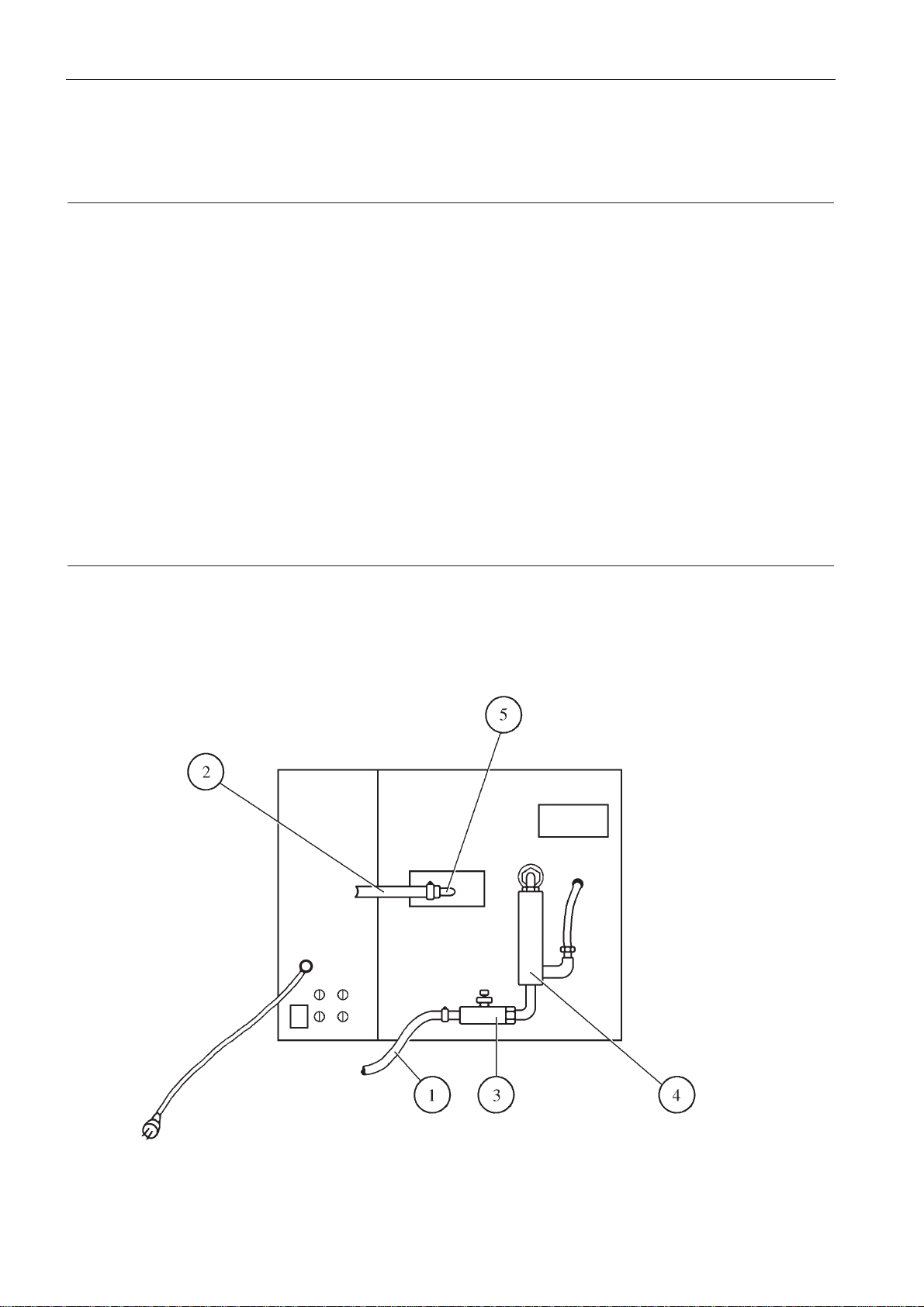
2.5. Electrical connection . . . . . . . . . . . . . . . . . . . . . . . . . . . . . . . . . . . . . . . . . . . . . . . . . . . . . . . . . . . . . . . . . . . . 2-2
2.6. Water connection . . . . . . . . . . . . . . . . . . . . . . . . . . . . . . . . . . . . . . . . . . . . . . . . . . . . . . . . . . . . . . . . . . . . . . . 2-2
CHAPITRE 3 - SPECIFICATIONS . . . . . . . . . . . . . . . . . . . . . . . . . . . . . . . . . . . . . . . . . . . . . . . . . . . . . . . . . . 3-1
3.1. Weight and dimensions . . . . . . . . . . . . . . . . . . . . . . . . . . . . . . . . . . . . . . . . . . . . . . . . . . . . . . . . . . . . . . . . . 3-1
3.2 Mains electricity . . . . . . . . . . . . . . . . . . . . . . . . . . . . . . . . . . . . . . . . . . . . . . . . . . . . . . . . . . . . . . . . . . . . . . . 3-1
3.3 Water supply . . . . . . . . . . . . . . . . . . . . . . . . . . . . . . . . . . . . . . . . . . . . . . . . . . . . . . . . . . . . . . . . . . . . . . . . . . 3-1
3.4 Capacity by volume of media . . . . . . . . . . . . . . . . . . . . . . . . . . . . . . . . . . . . . . . . . . . . . . . . . . . . . . . . . . . . 3-2
3.5 Mixing speed . . . . . . . . . . . . . . . . . . . . . . . . . . . . . . . . . . . . . . . . . . . . . . . . . . . . . . . . . . . . . . . . . . . . . . . . . . 3-2
3.6 Chamber specification . . . . . . . . . . . . . . . . . . . . . . . . . . . . . . . . . . . . . . . . . . . . . . . . . . . . . . . . . . . . . . . . . . 3-2
3.7 Timing of standard processing cycle . . . . . . . . . . . . . . . . . . . . . . . . . . . . . . . . . . . . . . . . . . . . . . . . . . . . . . 3-2
3.8 Temperature control . . . . . . . . . . . . . . . . . . . . . . . . . . . . . . . . . . . . . . . . . . . . . . . . . . . . . . . . . . . . . . . . . . . . 3-2
3.9 Cycle timing control . . . . . . . . . . . . . . . . . . . . . . . . . . . . . . . . . . . . . . . . . . . . . . . . . . . . . . . . . . . . . . . . . . . . 3-3
3.10 Overpressure valve settings . . . . . . . . . . . . . . . . . . . . . . . . . . . . . . . . . . . . . . . . . . . . . . . . . . . . . . . . . . . . . . 3-3
CHAPITRE 4 - INSTRUCTIONS FOR USE . . . . . . . . . . . . . . . . . . . . . . . . . . . . . . . . . . . . . . . . . . . . . . . . . . . . 4-1
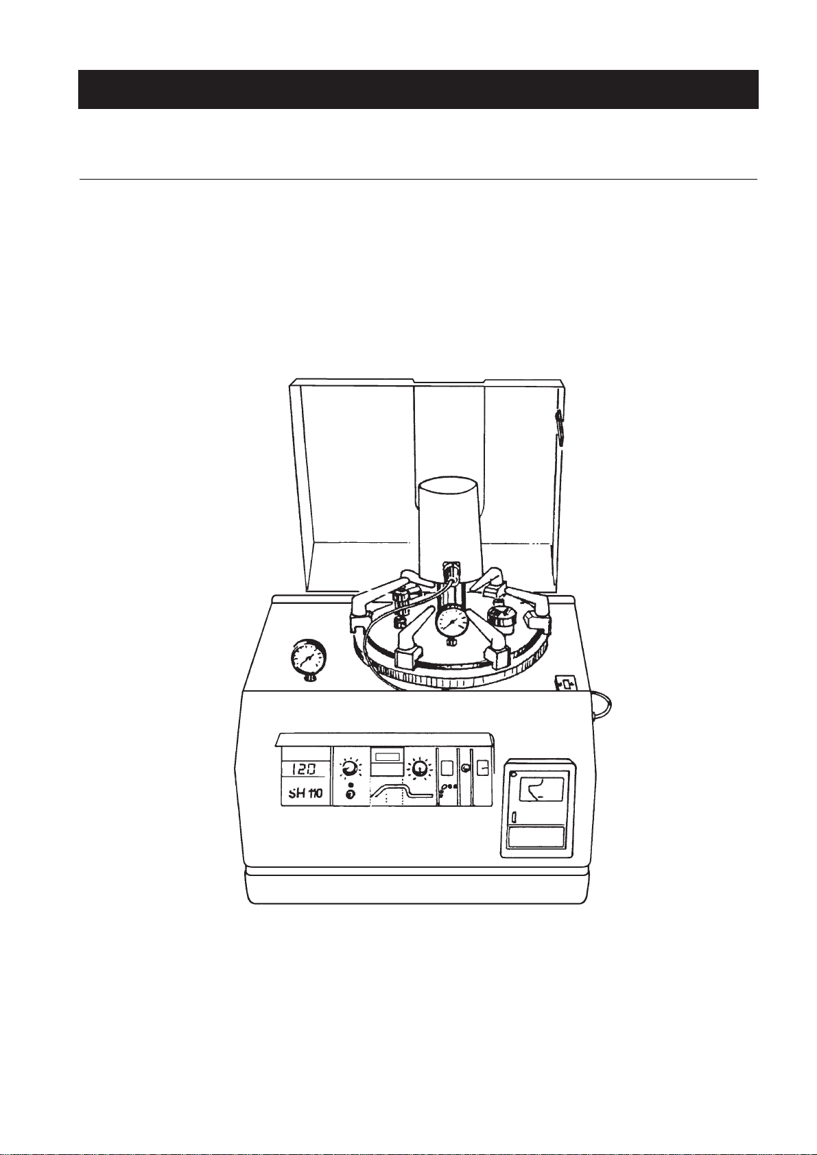
4.1. Description . . . . . . . . . . . . . . . . . . . . . . . . . . . . . . . . . . . . . . . . . . . . . . . . . . . . . . . . . . . . . . . . . . . . . . . . . . . . 4-1
4.2. Setting up . . . . . . . . . . . . . . . . . . . . . . . . . . . . . . . . . . . . . . . . . . . . . . . . . . . . . . . . . . . . . . . . . . . . . . . . . . . . . 4-6
4.3 Use . . . . . . . . . . . . . . . . . . . . . . . . . . . . . . . . . . . . . . . . . . . . . . . . . . . . . . . . . . . . . . . . . . . . . . . . . . . . . . . . . . . 4-7
4.4 Voluntary or involuntary interruption of the process . . . . . . . . . . . . . . . . . . . . . . . . . . . . . . . . . . . . . . . . . 4-9
4.5 Maintenance after use . . . . . . . . . . . . . . . . . . . . . . . . . . . . . . . . . . . . . . . . . . . . . . . . . . . . . . . . . . . . . . . . . . . 4-10
CHAPITRE 5 - HAZARDS, PRECAUTIONS AND LIMITATIONS OF USE . . . . . . . . . . . . . . . . . . . . . . . . . . . . . 5-1
5.1. Risks . . . . . . . . . . . . . . . . . . . . . . . . . . . . . . . . . . . . . . . . . . . . . . . . . . . . . . . . . . . . . . . . . . . . . . . . . . . . . . . . . 5-1
5.2. Safety . . . . . . . . . . . . . . . . . . . . . . . . . . . . . . . . . . . . . . . . . . . . . . . . . . . . . . . . . . . . . . . . . . . . . . . . . . . . . . . . . 5-1
5.3 Precautions . . . . . . . . . . . . . . . . . . . . . . . . . . . . . . . . . . . . . . . . . . . . . . . . . . . . . . . . . . . . . . . . . . . . . . . . . . . . 5-5
CHAPITRE 6 - SERVICING AND PREVENTATIVE MAINTENANCE . . . . . . . . . . . . . . . . . . . . . . . . . . . . . . . 6-1
6.1. Cleaning . . . . . . . . . . . . . . . . . . . . . . . . . . . . . . . . . . . . . . . . . . . . . . . . . . . . . . . . . . . . . . . . . . . . . . . . . . . . . . 6-1
6.2. Troubleshooting . . . . . . . . . . . . . . . . . . . . . . . . . . . . . . . . . . . . . . . . . . . . . . . . . . . . . . . . . . . . . . . . . . . . . . . 6-1
6.3. Spare parts list . . . . . . . . . . . . . . . . . . . . . . . . . . . . . . . . . . . . . . . . . . . . . . . . . . . . . . . . . . . . . . . . . . . . . . . . . 6-2
CONTENTS

SH-U
1 - 1
1USE AND FUNCTION
1.1. OVERVIEW
The SH105 and SH110 media preparators are automatic units for the preparation of culture media. They
mix the constituents (water - dehydrated ingredients - additives . . .) and also sterilise and cool the me-
dium according to data supplied by the operator.
Many types of agar can be prepared including delicate ones such as heated blood-agar and fresh blood-
agar.
FIG. 1.1 - VIEW OF THE SH 110

SH-U
1 - 2
1.2. FLUIDS
The fluids contained in the bowl must not be:
-explosive,
-comburants,
-inflamable,
-toxic.
All the fluids used must belong to the group 2 of the European Pressure Directive 97/23 CE.
Fluid used in the heating chamber (external circuit) = water (see Chapter 2.5).
1.3. ACCESSORIES
The SH105 - SH110 are supplied complete with the following accessories :
-1set spare fuses,
- 2 sets water connecting pipes,
- 2 sets Serflex hose couplings,
- 1 set seals for chamber and lid,
- 2 dispensing port nipples with silicon tubing,
- 2 dispensing port locking cap,
- 1 unlocking tool for safety cover,
- 1 chamber cover stand,
- 1 paper roll for units fitted with recorder.

SH-U
2 - 1
2.1. UNPACKING
Check that the parts on the packing list are included in the package. If any parts are missing, contact your
JOUAN agent.
Remove all accessories and paperwork.
2.2. LIFTING AND TRANSPORT
Due to the weight of the machine, all lifting and transporting must be carried out using proper handling
equipment (eg : fork lift trolley) that complies with current regulations, and by people having undergone
the necessary training.
The machine must be supported from underneath. If it has to be transported without its pallet, for example
on a staircase, professional handling assistance is required.
Carefully lift the unit by holding it at the sides.
Never attempt to lift the unit by the front, the cover or the pipes coming out of the back.
2.3. WORK SURFACE
Place the media preparator on a work surface that does not produce vibrations.
This surface must be at a height of about 0.850 m to facilitate working conditions, and close to a water and
electricity supply. It must be able to support the weight of the unit under working conditions (+8 kg for the
SH105 ; +14 kg for the SH110).
2.4. ENVIRONMENTAL CONDITIONS
This instrument is designed to operate safely under the following conditions:
-Indoor use.
-Temperature : 5° to 40°C.
-Maximum relative humidity of 80% for temperatures up to 22°C.
-Maximum altitude : 2000 m.
Maximum performance is assured across the following temperature range : 15°C to 25°C.
This instrument is not designed to resist an earthquake.
2INSTALLATION PROCEDURE

SH-U
2 - 2
2.5. ELECTRICAL CONNECTION
Connect the supply cable to the mains.
The electricity supply must be single-phase, 1 live, 1 neutral and 1 earth.
The SH105 requires 10 A at 220 - 240 V A.C. (50 or 60 Hz depending on type).
The SH110 requires more power : 13 A at 220 - 240 V.
The unit must be earthed for personal safety.
The SH105/SH110 media preparators have a built-in mains cable.
Remember that in order to respect the electrical safety standards related to protection against indirect
contact, the supply of power to the instrument must be via a power socket fitted with a protection device
ensuring automatic cut-off in the case of an insulation fault.
A supply fitted with a circuit breaker of the correct rating complies with this requirement.
2.6. WATER CONNECTION
The unit is supplied complete with connecting tubes and couplings. Connections are made at the rear of
the unit.
FIG. 2.1 - WATER CONNECTION

SH-U
2 - 3
1. Water inlet tubing
2. Water outlet tubing
3. Pressure regulator
4. Water level detector
5. Steam condensor
2.6.1 WATER INLET
The water supply pressure must be at least 2 bars. The water supply temperature must be between 10°C
and 30°C if the unit is to work properly.
The supply tube is connected to the lower port (point 1 and 3) with a hose coupling to ensure a water-tight
connection.
2.6.2 WATER OUTLET
Despite the inclusion of a steam condenser in the hydraulic circuit outlet, a water discharge connection
capable of withstanding boiling water under pressure is required. The discharge pipe is connected to the
upper port (point 5) at the rear of the unit with a clamp.
Care must be taken to ensure that the other end of the discharge pipe is located so as to prevent steam
under pressure being released into the room.

SH-U
3 - 1
3.1. WEIGHT AND DIMENSIONS
3SPECIFICATIONS
SH105 SH110
Net weight (kg) 38 46
Gross weight (kg) 42 50
Width (mm) 520 520
Depth (mm) 530 530
Height : lid closed (mm) 650 650
Height : lid open (mm) 800 800
3.2. MAINS ELECTRICITY
220-240 V / 50 Hz single-phase + earth
230 V / 60 Hz single-phase + earth
3.2.1 CONSUMPTION
* Values at 240 V / 50 Hz
3.2.2 HEATING POWER
3.2.3 ELECTRICAL INSULATION CLASS
Class I as per European and American standards.
3.3. WATER SUPPLY
Minimum mains water pressure > or = 2 bars.
Temperature of mains water 10° ≤T°C <30°
SH105 SH110
Min. 0.4 A 0.4 A
Max. 9 A * 10.5 A *
SH105 SH110
Standard 1500 W 2000 W
Max. 1800 W 2380 W

SH-U
3 - 2
3.4. CAPACITY BY VOLUME OF MEDIA
SH105 0.5 to 5 L.
SH110 1.3 to 10 L.
3.5. MIXING SPEED
45 rpm
3.6. CHAMBER SPECIFICATION
Stainless steel
Chambers tested to 9 bars
3.7. TIMING OF STANDARD PROCESSING CYCLE
3.8. TEMPERATURE CONTROL
3.8.1 STERILISATION RANGE
80 to 130 °C ±1°C
3.8.2 DISPENSING RANGE
30 to 80°C ±0.5°C
SH105 SH110
Heating 20° to 121°C 45 min 60 min
Sterilising 20 min 20 min
Cooling 121°C to 40°C 15 min 25 min
TOTAL 1 h 20 min 1 h 45 min

SH-U
3 - 3
3.9. CYCLE TIMING CONTROL
By programmable timer adjustable by means of four buttons located under the display:
The lower number indicates the setpoint time for sterilisation.
The upper number indicates the time left for sterilisation.
Do not use the “Valid” and “MODE” button.
3.10.
OVERPRESSURE VALVE SETTINGS
Heating chamber : 32 psi (2.2 bars)
Inner chamber : 32 psi (2.2 bars)
Heating chamber security : 41 psi (2.8 bars)- CE model only.
FIG. 3.1 - TIMER

SH-U
4 - 1
4INSTRUCTIONS FOR USE
4.1 DESCRIPTION
4.1.1 GENERAL VIEW
The unit is mounted on a rigid chassis with painted sheet metal closed-in sides.
FIG. 4.1 - GENERAL VIEW

SH-U
4 - 2
4.1.2 FRONT PANEL, CONTROL PANEL
Control panel and, depending on model, medium temperature recorder.
The control panel is protected from splashing by a sliding transparent screen.
Behind the front panel is the electronic rack protected by a cover and cooled by the fan mounted on the
right hand side of the unit..
1. On/off mains switch
2. Fast cooling pushbutton
3. Blood-agar pushbutton
4. Dispensing temp-adjust
5. Dispensing indicator light
6. Timer
7. Temp-display
8. Sterilisation indicator light
9. Sterilisation temp-adjust
10. Heating indicator
11. Start pushbutton
FIG. 4.2 - CONTROL PANEL
1. Acrylic cover
2. Motor
3. Motor and probe plug
4. Locking system
5. Sterilization indicator light
6. Dispensing indicator light
7. Temperature display
8. Sterilization temp-adjust
9. Start pushbutton
10. Heating indicator
11. Timer
12. Dispensing temp-adjust
13. Blood agar pushbutton
14. Fast cooling pushbutton
15. On/off mains switch
16. Temperature recorder
17. Heating jacket pressure gauge
18. Control panel protective lid
19. Additions port
20. Safety valve
21. Locking handle
22. Dispensing port
23. Decompression valve

SH-U
4 - 3
4.1.3 REAR PANEL
The rear consists of two painted panels :
-Left : fuses and mains lead and on/off mains isolation switch.
-Right : hydraulic circuit inputs and outputs, pressure regular and water-level indicator.
1. Mains cord
2. Mains fuse (Q = 1)
3. Electronique fuse
4. Motor fuse
5. Water inlet tubing
6. Water outlet tubing
7. Pressure regulator
8. Water level detector
9. Steam condensor
10. Identification plate
11. On/off mains isolation switch (CE model only)
FIG. 4.3 - BACK OF SH 105 / SH 110

5
4
3
2
6
7
8
1
SH-U
4 - 4
4.1.4 TOP VIEW
The top is made of stainless steel plate with :
- Pressure gauge connected to the heating jacket to measure the pressure in the hydraulic circuit.
- Acrylic safety cover fitted with a locking latch which, in the closed position, fits into the locking hole.
- Heating jacket which holds the medium sterilisation chamber.
- The chamber is closed by a removable and lockable cover.
- The cover houses the following components :
- Motor driving the medium mixing paddle contained in the preparation chamber.
- Medium temperature probe.
- Medium dispensing port.
- Safety valve.
-Manually operated decompression and pressurising valve for the preparation chamber.
- Pressure gauge to measure the pressure in the preparation chamber.
- Quick action 6-pin plug supplying power to the mixing motor and connecting the temperature probe to
the electronic rack. The cover is clamped in place (4 clamps on the SH105, 6 on the SH110).
FIG. 4.4 - TOP VIEW OF VESSEL LID
Platinum probe
Valve
Dispensing port
6 pin plug
(motor + probe)
Pressure gauge
Safety valve
Additions port
Motor
To electronic rack

SH-U
4 - 5
4.1.5 HYDRAULIC SYSTEM
FIG. 4.5 - HYDRAULIC CIRCUIT
Safety valve
(CE model only)
1. Heating chamber
2. Preparation chamber
3. Heating element
4. Water inlet tubing
5. Pressure regulator
6. Water level detector
7. Water entry electrovalve
8. Flexible tubing
9. Non-return valve
10. Water discharge electrovalve
11. T connector
12. Steam condensor
13. Water discharge tubing
14. Dispensing port
15. Mixing paddle
16. Heating chamber pressure gauge
17. Preparation chamber pressure gauge
18. Lid seal
19. Chamber seal
20. Temperature probe
21. Decompression valve head
22. Decompression valve
23. Safety valve
24. Additions port
25. Additions port cap
26. Manual reset safety thermostat
27. Chamber lid

SH-U
4 - 6
4.2. SETTING UP
4.2.1 SAFETY COVER
The unit is fitted with an acrylic safety cover which is locked in the closed position when the unit is not
switched on and the temperature of preparation chamber is above 65°C.
Do not attempt to remove the cover when the unit is switched off.
The safety cover unlocks automatically when the unit is switched on with the green switch on the control
panel (rep.15 chap. 4.1.2). Lift the safety cover and then switch off.
4.2.2 CLEANING THE PREPARATION CHAMBER
-Undo the locking handle (rep 21 chap. 4.1.1) (the handles are released by an up or down movement
according to the model).
-Disconnect the electric plug connecting the motor to the unit (point 3 chap. 4.1.1) by turning the metal
ring to the left and pulling.
-Lift the chamber cover clear holding it by the isolating handle (underneath the black cover). Place the
chamber cover on the stand supplied. The chamber cover must be handled with care to avoid damage
to the temperature probe(cf 20 chap. 4.1.5), dispensing tube (cf. 14 chap. 4.1.5 or cf 3 chap. 4.1.4 ) and
mixing paddle.
-Remove the preparation chamber (cf 2 chap. 4.1.5) and wash in clean water to avoid foreign bodies in
the medium.
-Check that there are no foreign bodies in the heating chamber (cf 1 chap. 4.1.5) which might damage the
water circulation electrovalves.
4.2.3 PRELIMINARY OPERATIONS
-After cleaning, replace the preparation chamber in the heating chamber. Check the condition of the seal
(cf 19 chap. 4.1.5).
-Fill the chamber with water (preferably distilled or demineralised) and dehydrated medium in the
required proportions (up to 5 litres of medium in the SH105 and 10 litres in the SH110)
Warning : Keep within the maximum permitted amounts of water. Exceeding these limits will cause
excess pressure and operate the safety cut-out.
Replace the chamber cover, with the pressure gauge and motor plug to the front to allow all the locking
handles to turn freely.
-Replace the cover clamps.
-Gradually tighten the locking handles in a criss-cross fashion (one handle then the one opposite, the next
handle and the one opposite etc...) in order to ensure a uniform compression of the seals.
-After tightening the handles, release and turn them inwards to allow the safety cover to close.

SH-U
4 - 7
Important :
-Remove the decompression valve head (point 21 figure 4.5) and fill with carded (sterile) cotton-wool to
ensure filtering of bacteria during dispensing phase (see. Ch. 4.3, phase 6).
The unit is now ready for use.
4.3. USE
4.3.1 STANDARD OPERATING CYCLE
The cycle operating cycle consists of 6 phases.
Phase 1 : Preparation and checking
Before use, the unit must comply with the following conditions :
- Correctly connected to water and electricity.
-Medium (water and ingredients) in the chamber.
-Cover clamped and locked.
-Additive and dispensing ports hermetically sealed.
-Decompression valve : milled knob must be unscrewed (decompression takes place by tightening
knob).
-6-pins plug connected to motor assembly.
-Safety cover on.
-Fresh carded cotton-wool in the decompression unit.
Phase 2 : Starting up
With the unit still switched off :
-Set sterilising T°C as required
-Set dispensing T°C as required
-Set sterilising time as required using the four buttons located under the timer display
-The unit is ready to operate.
Start the unit : Press on/off switches (back panel and front panel).
-The mains switch green light comes on.
-The mixing motor starts up (motor noise audible).
-The digital display shows the temperature of the medium.
Press the START button .
-The sterilising cycle indicator light comes on .
-The input and output electrovalves open allowing water to fill the heating jacket.
NB :
- Water supply pressure must be > or = at 2 bars for the chamber to fill correctly.
- An electronic timing mechanism ensures the water circulates for about 45 seconds.
- A flow monitor engages for a continuous flow in excess of 2 L/min.
- An electronic circuit operates the sterilising cycle if the flow x discharge time conditions are satisfactory.
- The heater comes on (amber light).
This manual suits for next models
1
Table of contents
Other Jouan Laboratory Equipment manuals
Popular Laboratory Equipment manuals by other brands

Huvitz
Huvitz SMART BLOCKER HBK-410 user manual

IKA
IKA IKAMAG Maxi MR 1 operating instructions

Monmouth Scientific
Monmouth Scientific Circulaire HLFT1000 operating & maintenance manual

Swan Analytical Instruments
Swan Analytical Instruments AMI Codes-II CC Operator's manual

Civco
Civco GUS G10VPL Operator's manual

Biotage
Biotage Turbo Vap II quick start guide