3. Press the Auto button and you should see within a few seconds a square wave
of about 2V peak-to-peak at 1KHz in the display. Repeat the steps to observe CH2.
• Probe check
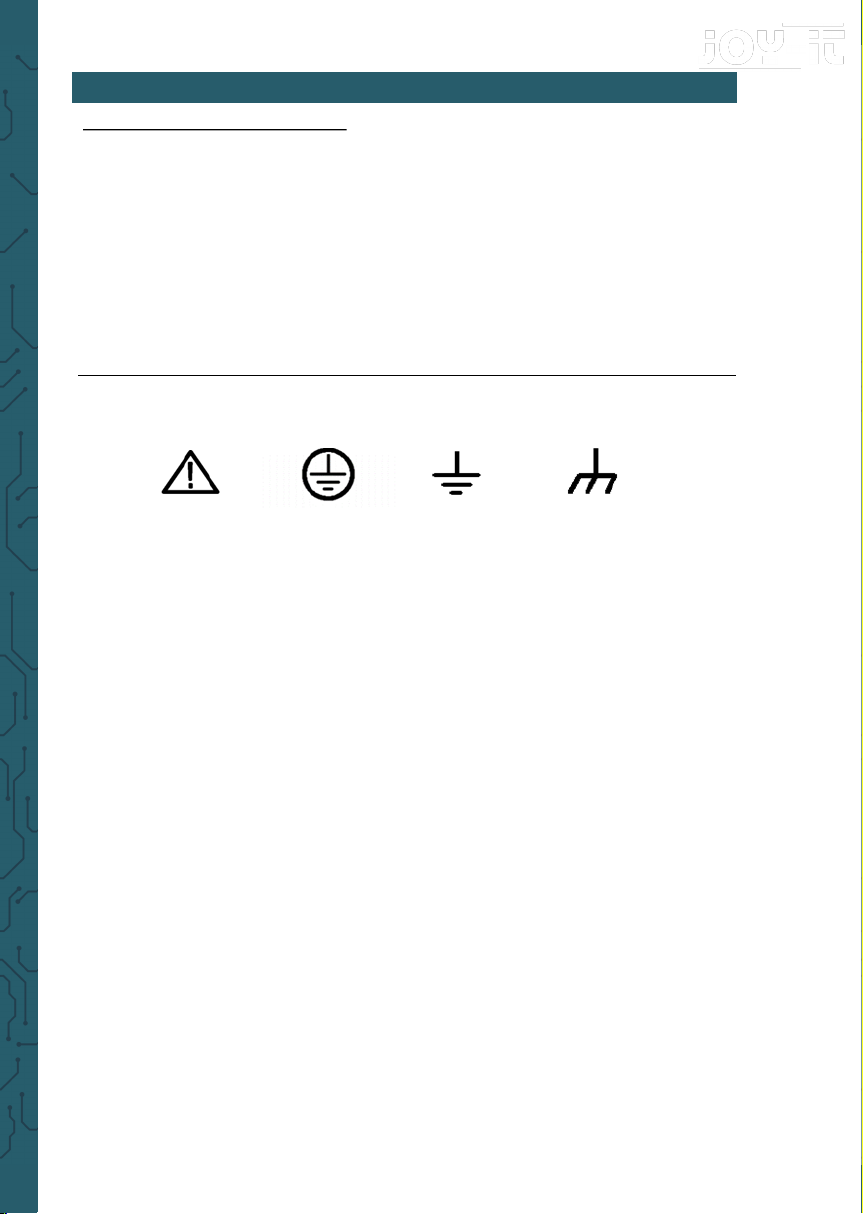
Safety
When using the probe, keep your fingers behind the
guard on the probe body to avoid electric shock. Do
not touch metallic portions of the probe head while it
is connected to a voltage source. Connect the probe to
the oscilloscope and connect the ground terminal to
ground before you start any measurements.
Manual Probe Compensation
Upon the first connection of a probe and an input channel, you should manually
perform this adjustment to match the probe to the input channel. Uncompensated
or wrong compensated probes may lead to errors or faults in measurement. To
adjust the probe compensation, follow the steps below.
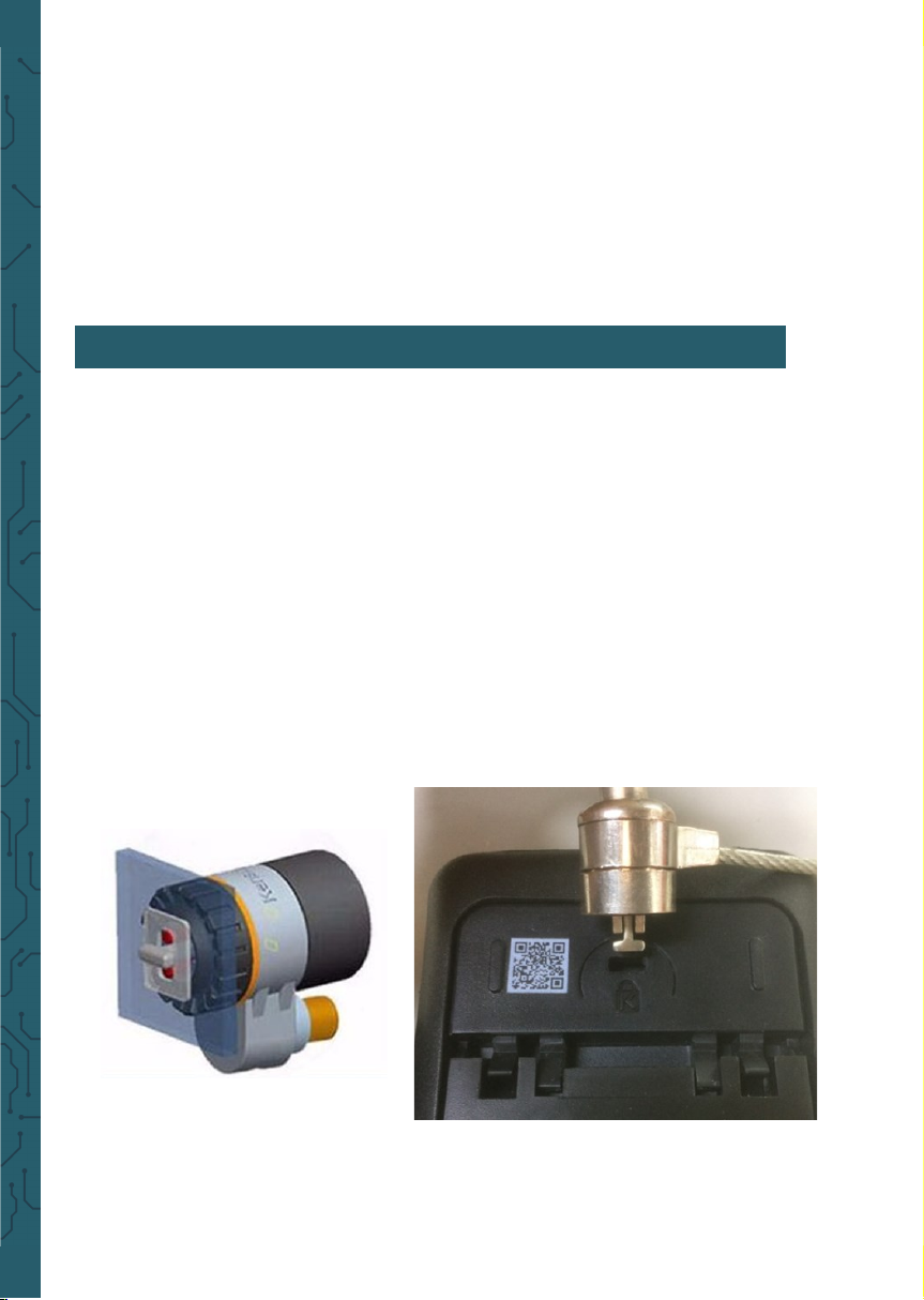
1. Press Channel button to enter channel setting menu, Set the Probe option at-
tenuation in the channel menu to 10X. Set the switch on the probe to 10X and con-
nect the probe to Channel 1 on the oscilloscope. If you use the probe hook-tip, the
hook end should be removed, the probe pin should be inserted into the Gen Out
output terminal, and the probe grounding clamp should be clamped on the metal
outer ring of the Gen Out output terminal. The oscilloscope with signal generator
function needs to set output signal as 2V @ 1KHz square wave; The Gen Out termi-
nal of the oscilloscope without signal generator function automatically outputs 2V
@ 1KHz square wave. Press the Auto button.
2. Check the shape of the displayed waveform.
3. If necessary, use a nonmetallic screwdriver
to adjust the variable capacity of your probe
until the shape of the waveform turns to be
the same as the above figure. Repeat this step
as necessary. See the figure below for the way
of adjustment.
Probe Attenuation Setting: Probes are of
various attenuation factors which aect the
vertical scale of the signal. The Probe Check
function is used to verify if the Probe attenua-
tion option matches the attenuation of the probe.
Compensated correctly
Overcompensated
Undercompensated