JP F38 HORNET User manual

J Perkins Distribution
www.jpekins.com
ASSEMBLY & OPERATING
MANUAL

FUN WITH A CAPITAL ‘F’
Welcome, and congratulations on purchasing an F38 Hornet, an eye-catching, performance
delta that has the ability to provide maximum excitement for minimal outlay and preparation
time. Equipped with a powerful pre-fitted 1200KV brushless motor, 30A ESC and capable twin
9g servos, a few simple steps is all it takes to get this futuristic 3-channel PNP racer punching
3S-fuelled holes in the sky. Docile, dead easy to launch and furiously fast the JP F38 Hornet
is the perfect all-weather grab ‘n’ go racer. Suitable for any occasion and almost any field it’s a
model you should fly only if you’re a competent (and confident) R/C pilot. It’s also a model
that deserves to be shared and flown alongside other F38s, whether that be in organised
pylon racing heats or just having a crack at the field with your mates. We give you the F38,
then. Fun, with a capital F.
As the owner and operator of this product you are solely responsible for flying it in a
manner that does not endanger yourself and others or result in damage to your F38 or
the property of others.
Always make sure you fly the model with an active fail-safe that’s set to cut the throttle in
the event of a loss of radio signal.
Always operate the model in an open area that’s well away from cars, traffic or people
and that’s approved for the flying of model aeroplanes.
This is not a toy and not suitable for children under the age of 14 or anyone without prior
model piloting experience.
Never fly this model in populated areas.
Always start a flight with fully charged batteries.
Always treat the propeller as LIVE when the battery is connected.
Keep well clear of the propeller when the battery is connected, even if it’s stationary.
Very serious injury and significant damage can easily occur when live propellers are not
respected.
Carefully follow the directions and warnings for this model and any operational support
equipment that you use in combination with it, i.e. chargers, LiPo batteries and radio
control equipment.
Water and moisture is damaging to electronic equipment. Avoid exposure to water and
moisture at all times.
Never operate the model with low transmitter batteries.
SAFETY PRECAUTIONS & WARNINGS
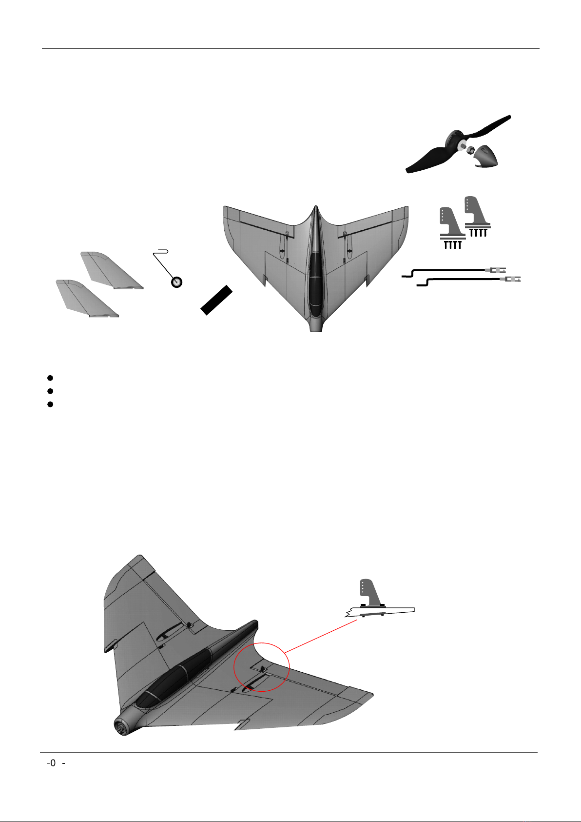
SPECIFICATION
Wingspan: 800mm / 31.5in.
Length: 550mm / 21.7in.
Airframe: Durable EPO.
Flying weight: 560g / 19.8oz
Total surface area: 24.5dm
Motor: 2834-1200KV brushless
ESC: 30A
Propeller: 8 x 6”
Servos: 9g
2

BOX CONTENTS
Before you start the final assembly of your F38 please check that the following components
are present and correct.
1x Airframe with factory installed motor, ESC, and twin 9g servos.
2x Vertical stabilizer fins.
1x Nose landing gear assembly (leg and wheel).
2x Servo pushrod with clevis.
1x Spinner.
1x 8 x 6” tuned propeller.
2x Elevon control horns.
1x Hook and loop strip.
Foam safe glue.
3-channel 2.4GHz transmitter and receiver combo with elevon mixing.
Radient 2200mAh 30C 3s LiPo with XT60 connector.
REQUIRED TO COMPLETE
1. Attach the control horns
Attach one control horn and backing plate to each control surface using four of the eight
control horn screws provided. The position of each horn is identified by a clearly visible indent
in the foam. Ensure all the screws pass through the control horn, into the backplate, and that
the horn is firmly secured and displays no movement. Failure to attach the horns securely
could cause them to become loose in high-speed flight, with catastrophic results.
Note:
It is normal for the screws
and mounting plates to
slightly compress the
foam (by 1mm). This
ensures a firm fixing.
3
ASSEMBLY INSTRUCTIONS

2. Install the receiver
Select a new model memory on your transmitter and set the appropriate delta / elevon mix.
Connect the two servos and the ESC to the receiver as shown in the diagram or, if different, in
accordance with the delta / elevon mix channel allocations dictated by your particular radio
brand. Install the receiver behind the ESC. Please ensure you run your receiver antenna(s)
clear of the ESC to limit any possible RF interference.
Note: The ESC included with this model has a Safe Start facility. If the battery is
connected to the ESC and the throttle stick is not set to the low (OFF) position the
motor will not start until the throttle stick is moved accordingly. Once the throttle stick
is moved to the OFF position the ESC will emit a series of beeps. Several beeps of the
same note means that the ESC has detected the cell count of the battery. The beep
count will equal the number of cells in the battery (3S battery = 3 beeps). TAKE GREAT
CARE. At this point the motor will be armed and will start when the throttle is moved.
3. Install the battery
Before connecting the recommended Radient 3S 2200mAh 30C battery (ref.
RDNB22003S30XT60) please make sure that the propeller is NOT attached. Connect the
battery then allow the the ESC to calibrate and arm, a process confirmed by a series of
audible beeps (see note below). Check that the throttle and servos are operating correctly
then centre the servos ready for the pushrods to be installed.
4. Attach the pushrods
With the servos set to neutral and the control surfaces set flush with the outboard wing
section, as shown in the image below (the inboard end of the control surface will be slightly
above the wing section), the control rods can be adjusted to the correct length by screwing
the clevis in or out. Note that the clevis must be attached to the control horn NOT the servo.
Connect the clevis to the outermost point on the control horn. Two small pieces of tubing are
supplied to place over the clevis arms once in position to prevent the arms from opening. As
an important safety measure this small detail must be checked before every flight to ensure
that the clevis is firmly attached to the control horn.
Outermost hole.
Clevis lock in position.
A
B
C
Note:
Once fitted please check the flight
control for full and free movement.
Twist to adjust the
pushrod length.
Control Surface
neutral position.
4

Fin Base
Note: The base of each
fin incorporates a slight
angle at the trailing
edge which mirrors the
swept leading edge of
the control surface. If
you choose the inward-
facing fin arrangement
you’ll need to dry fit
each, mark the cut
position on the base,
then trim to fit (as
shown) before gluing
firmly in place.
Fin Base
Cut position
5. Attach the vertical fins
You have two options when attaching the fins. Primarily designed to be fixed in an outward-
facing arrangement it is also possible to mount the fins facing inward. The effect of an inward
stance is one of appearance and a slightly increased rate of roll. Note, however, that if you
choose to angle the fins inward a modification is required to the base of each where it meets
the control surface at the trailing edge. Here, you’ll need to make a small cut so as to not
impede the control surface travel (see below). Having decided on the fin style you want and
having made any necessary adjustment, simply glue in place.
6. Fit the propeller and spinner
Ensure that the LiPo pack is disconnected and removed from the model. Attach the spinner
backplate and tuned 8 x 6” propeller to the motor shaft using the supplied washer and nut.
Make sure you firmly tighten the nut. Use the two remaining screws to secure the spinner
cone.
5

7. Fit the nose leg
The nose leg is optional on your F38 however it can save the propeller on landing. The leg
simply pushes into the landing gear support bearer located on the underside nose section of
the model.
8. Install your 3S LiPo battery
The position for the battery is shown in the illustration below. The space is designed for a
Radient 2200mAh 3s 30C LiPo or an alternative of a similar size. Use the supplied hook and
loop strap to secure the battery in position. As a belt and braces fix we also recommend using
additional self-adhesive hook and loop tape (not supplied) on the plywood base and battery
underside.
9. Check the control surfaces
See below for our recommended control surface movements. These are a good starting point,
however once you’ve flown your F38 you may find you want to adjust to suit your flying style.
6
Rate
Aileron
Elevator
Aileron (Low Rate) Aileron (Hi Rate) Elevator (Hi Rate)
Elevator (Low Rate)

10. Check the Centre of Gravity (balance point)
Use the image below to set the C of G. Do this by moving the battery forward or aft until the
correct position has been found. Finally, mark the desired battery position on the inside of the
battery bay in order to precisely locate the pack each time you fly.
11. Go flying
For your first flight it's always best to get someone with experience to launch your F38,
however do note the desired 15° launch angle in the illustration below. Using the finger grips
on the underside of the fuselage, launch into wind, with a firm throw and with the throttle set
at between three-quarter and full power. Your F38 will leap into the air at which point you can
gain altitude, throttle back a little and add trim as necessary; you shouldn’t need much.
Once airborne the F38 displays all the characteristic traits of a performance delta, not least a
benign stall, comfortable handling and exhilarating speed. With a little stick time this is an
aeroplane you’ll quickly fall in love with. Take our advice, keep it in the boot of the car, fly it
lots and encourage a few friends to buy one in a different colour. One F38 in the air is
fabulous. Two, three, four (or more) is simply awesome. Enjoy.
7

This manual suits for next models
3
Table of contents
Popular Toy manuals by other brands

Eduard
Eduard P-39N/Q Airacobra Assembly instructions

iKarus
iKarus craftair Assembly instructions

MTHTrains
MTHTrains HO 2-8-4 Engineer's guide

Rolly Toys
Rolly Toys 080.000.800.00 quick start guide

roco
roco 73888 operating manual

Aria Child
Aria Child W446AC-Y Mini Cooper S Owner's manual and assembly instructions