JPS PD Series User manual

PD - Series
INSTRUCTION MANUAL
IGBTINVERTER

1
WARNING! !
Attentiontothese warning
signsonthe inverteror inthis
instructionbook.
Theyindicate danger to
humanbody or damageto
the inverter.
Before installingandputting
the inverterintooperation,
please readthesafety
precautions andwarnings
followingthispage.

2
Safetyprecautions & warnings
Read carefullyall thesafetyprecautionsincludedintheseoperatinginstructionsandallthewarning signsattachedto
theinverter.Makesurethatthewarningsignsare kept ina legibleconditionandreplace missingordamagedsigns.
Beforestarting, familiarizeyourselfwiththeoperationof theinverter.It maybe toolateifyoustartworkingwiththe
inverterbeforereadthis instructionmanual.
Neverpermitunqualifiedpersonnel tooperate theinverter.
!WARNING
Thisinverterproducesdangerous electricalvoltagesand controls rotatingmechanicalparts. Death,severeinjuryor
substantialdamage topropertycam occuriftheinstructionsinthis operating manualare notcomploedwith.
Onlypersonnel withappropriatequalificationsshouldworkwith this inverter.Thesepersonnelmustbe familiarwithall
thewarningsignsand precautionslaidout intheseoperatinginstructionsforthetransport,installationandoperationof
this inverter.
Thesuccessful andsafe useofthis inverterdependsonthecorrectinstallation, comissioning, operationand
maintenance of theinverter.
** ThePD inverteroperatesathighvoltages.
** TheDC-linkcapacitorremainchargedtodnagerous voltageseventhepoweris removed. Forthis reasonitis
notpermissibletoopenthe invertercoveruntiltenminutesafterthe powerhas
beenturnedoff. Whenhandlingtheopeninverteritshouldbe notedthatlive parts areexposed.
Donottouchtheselive parts.
** Thefollowingterminals cancarrydangerous voltagesevenifthe motoris inoperative:
ThepowersupplyterminalL1,L2/N (orR,S,T)
ThemotorterminalU,V,W
TheDC-linkterminalP,N
Thebrake resistorterminalBr+,Br-
** Onlyqualifiedpersonnelmayconnect, start thesystemup andrepairfaults.
Thesepersonnel mustbe thoroughlyacquaintedwithallthewarningsand operatingprocedures
contained withthismanual.
** Certainparametersettings maycausetheinvertertostartupautomaticallyafteraninputpower
failure.
DEFINITIONS
QualifiedPerson
Forthe purposesofthis manualandproductlabels. aqualifiedpersonis onewhois familiarwiththeinstallation,
construction, operationandmaintenance of this inverterandwith hazardsinvolved. Inaddition,the personmust be:
(1) Trainedandauthorisedtoenergize, de-energize, clear,ground and tagcircuitsand equipmentin
accordance with establishedsafetypractices.
(2) Trainedinthepropercareand useof protective equipmentin accordance withestablished
safetypractices.
(3) Trainedinrendering firstaid.
Danger
Forthe purposesofthis manualandproductlabels, DANGER indicatesthatloss oflife, severepersonalinjuryor
substantialpropertydamageWILL resultifproperprecautionsare not taken.
Warning
Forthe purposesofthis manualandproductlabels, WARNING indicatesthatloss of life, severepersonalinjuryor
substantialpropertydamageCAN resultifproperprecautions are nottaken.
Caution
Forthe purposeofthis manualandproductlabels, CAUTIONindicatesthatminorpersonalinjuryorpropertydamage
CAN resultifproperprecautionsare nottaken.
Note
Forthe purposeofthis manualandproductlabels, NOTES merelycall attentiontoinformationthatis especially
significantinunderstanding andoperatingthedrive.

3
!DANGER andWARNING
Makesurethatthelocationselectedforinstallationissafe, protectedfrommoistureand splashanddrip-proof!
Childrenand thegeneralpublic must be prevented from accessing or approachingtheequipment!
Theequipmentmayonlybe usedforthepurposespecifiedbythemanufacturer.
Unauthorizedmodificationsandthe useof sparepartsandaccessoriesthatare notsold orrecommendedbythe
manufacturerof theequipmentcancausefires,electricshocks andinjuries.
Keep theseoperating instructionswithineasyreach and givethemtoall users!
!WARNING
ThisisaClass Aproduct.Inadomestic environment thisproduct may causeradio
interference in which casethe usermay erequired to takeadequate measures.

4
CONTENTS
1. DESCRIPTIONOFPDSERIESINVERTER......................................................................................................5
1.1GENERAL DESCRIPTION AND DESIGN PHILOSOPHY ................................................................................................5
1.2HARDWARE INPUT & OUTPUTCONFIGURATION ....................................................................................................5
2. INSTALLATION...................................................................................................................................................8
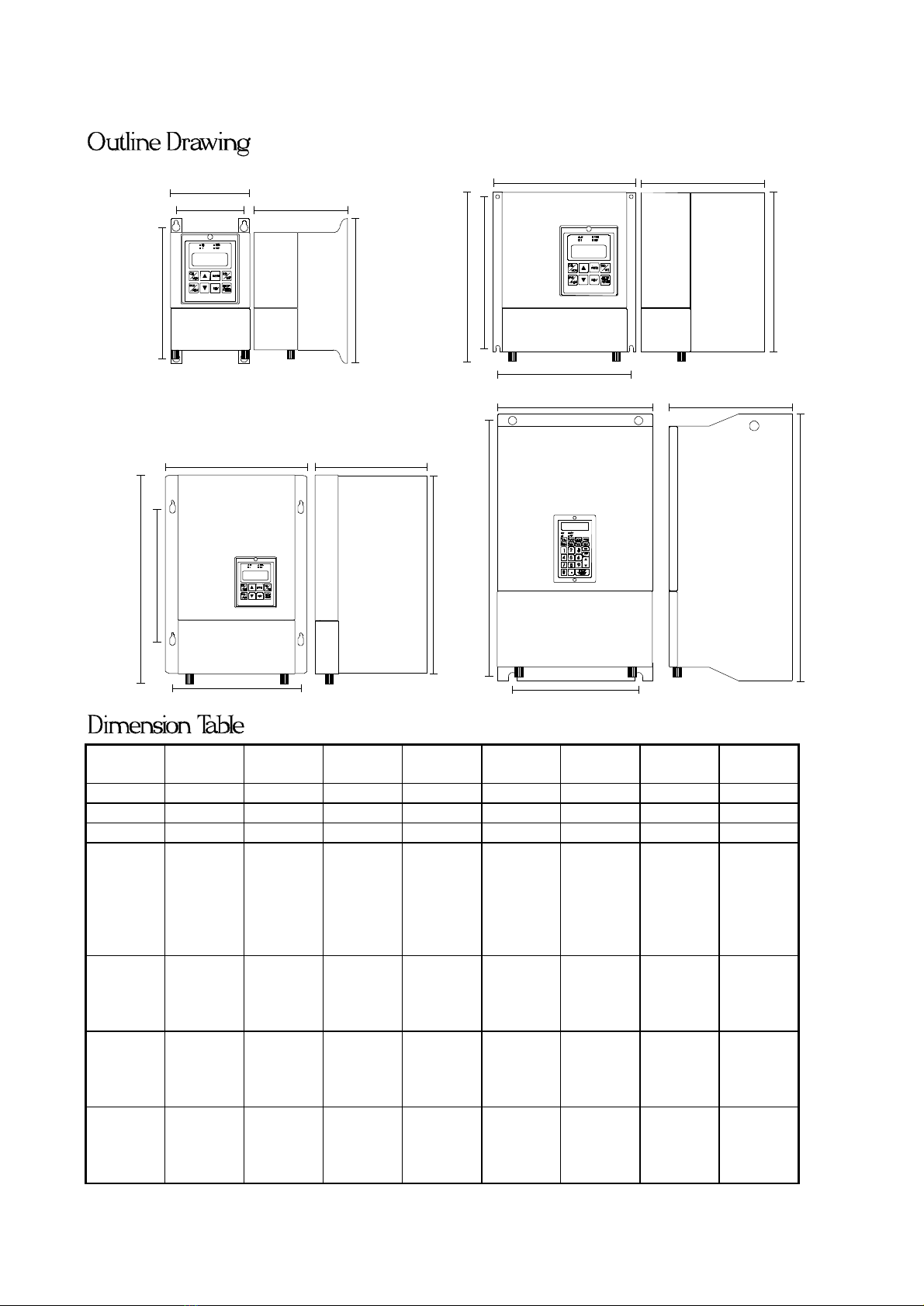
2.1OUTLINE DIMENSIONS.........................................................................................................................................9
2.2POWER TERMINAL.............................................................................................................................................10
2.3CONNECT POWER LINEINPUTTO INVERTER........................................................................................................11
2.4CONNECTINVERTER OUTPUTTO MOTOR ............................................................................................................11
2.5DC BUSOR BRAKE DISCHARGE TERMINAL ........................................................................................................11
2.6CONTROL TERMINAL CONNECTION.....................................................................................................................12
3. CONTROLPANEL.............................................................................................................................................13
3.1LOCALPANEL...............................................................................................................................................13
3.2REMOTEPANEL............................................................................................................................................14
4. SYSTEM START-UP...........................................................................................................................................16
4.1RESET &INITIALIZE THE INVERTER....................................................................................................................16
4.2SIMPLE START-UP &RUN BYKEY-PAD ..............................................................................................................16
4.3MONITOR THE INVERTER RUNNING STATUS ........................................................................................................16
4.4APPLY INVERTER TO YOUR SYSTEM....................................................................................................................16
5. PARAMETERS....................................................................................................................................................17
5.1PARAMETERSLIST......................................................................................................................................17
5.2PARAMETERPROTECTION.........................................................................................................................19
5.3PARAMETERSINITIALIZATION.................................................................................................................19
5.4DESCRIPTION OF ALLPARAMETERS ....................................................................................................................19
6. SELECTIONOFRUN/STOP/FWD/REV CONTROLCOMMAND.................................................................26
7. SELECTIONOFSET FREQUENCY INPUT SOURCE...................................................................................27
7.1SELECTION CHART......................................................................................................................................27
7.2SPEEDSOURCE DESCRIPTION...................................................................................................................28
8. SELECTIONOFDIGITALINPUT FUNCTION...............................................................................................36
9. SELECTIONOFDIGITALOUTPUTAND RELAYFUNCTION...................................................................42
10.SELECTION OFANALOGOUTPUT FUNCTION........................................................................................46
11.SPEED SEARCHAND BASEBLOCKFUNCTION........................................................................................47
12.AUTORUN FUNCTION...................................................................................................................................48
12.1AUTO MODESELECTION &RUNNING....................................................................................................48
12.2AUTO STEP EQUALOUTPUT.....................................................................................................................50
13.MONITORFUNCTION....................................................................................................................................51
13.1OPERATING STATUSCHECK....................................................................................................................51
13.2TERMINALSTATUSCHECK......................................................................................................................51
13.3A/DCONVERTERCHECK...........................................................................................................................51
14.MAINTENANCE&ERRORMESSAGE.........................................................................................................52
15.COMPUTER CONTROL..................................................................................................................................53
15.1PROTOCAL&FORMAT..............................................................................................................................53
15.2COMPUTERTO INVERTER.................................................................................................................................53
15.3INVERTER TO COMPUTER.................................................................................................................................54
15.4SAMPLEPROGRAM ..........................................................................................................................................55
16. BLOCKDIAGRAM OFPD-INVERTER.........................................................................................................58

5
1. Description of PD Series inverter
1.1General description and Design philosophy
ThePD SeriesinverterisaPOWERCONVERTERforvariable-speedAC drives.
It appliesthePulseWidthModulationmethodtocontrol the output voltage andfrequencytothe motor.Thedesign
ofhardware andfirmwarearebasedonadvancedmicroprocessortechnology.
PowerDevice "IGBT" is usedtoincreaseswitchingcarrierfrequencyforeliminatingthe motoroperationnoise.
ManyuniquefunctionsbuiltinthisInverterseries,areveryuseful tocustomersforallkindsof application.
Built-instandard UP/DOWNCounter Module,
Timer/Counter Moduleand Flip/Flop Modulewhich
areveryoftenusedinactualapplicationsystem.
Outputcurrent waveformis trimmedtorunthe motor
smoothlyevenifunderlow running frequency.
Special C.O.D.(Current Over Detector) Modulecan
monitoroutputcurrent andgeneratewarning signal
forsophisticatecontrol.
Fourdigitalinputsand three digitaloutputs are all
programmabletomeetallkindsof applications.
Two analoginputs AI1&AI2 areprovidedfor
voltage, current control.Moreover,thetwo inputs
can serve as AI1*AI2 or AI2+AI1 orother
combinationsout of yourimagination.
RS485 serialcommunication portisbuiltintothe
inverteras standard.Itisveryuseful wheninverter
ormanyinverterswould like tobe dynamical
controlled bymastercomputer.Withrepeaterone
serialportcanaddress upto99 inverters.
(StandardRS485 drivercandrive upto31inverters
only.)
Two typesofpanel LOCAL and REMOTE aredesigned for PD Series.Referto Section3 fordetaildescription.
ThePD Seriesinverteriscomposedbythree majorparts: PANEL ,CONTROLBOARD &POWER
CONVERSION UNIT.
1.2Hardwareinput & output configuration
Theterminalof thecontrol boardis:
CHBPG+AI1 ACOM AI2DI1DI2REV24VDO1DO2
CHAPG-AM5VDI3DI4RSTRUN DCOM RY1RY2
Note:Fourterminals "PG+","PG-", "CHA"and"CHB"are notusedinstandardPD Series,theyare reservedfor
PDF/PDV Series foraccuratespeedfeedback.
General
IGBT
Inverter
Wide purpose
PD Inverter
Up/Down
counter
TIMER
Flip/Flop
Auto-Run
C.O.D. RS-485
Multi-
Function
Digital
Input/
Output
and
Dual
Analog
Inputs

6
1.2.1Analog input blocks (Refer toSec. 7)
AI1 and AI2 are analoginputterminals.AM terminalis usedforanalogsignaloutput.
ACOM is thecommonterminalforanalogcircuit.The 5V terminalsupplyanalog+5volt.
Insidethecontrolboard,thereare two jumpers JP1 and JP2.
1.2.1.aAnaloginput AI1module
JP1 is usedtodefine thecharacteristicof theinputterminals AI1.
Ifyouareusingexternalanalogvoltage0~+10Vinput,pleaseuse AI1 and
select JP1 to +10V position.
Ifyouareusingexternalanalogvoltage-5V~+5Vinput,pleaseuse AI1
andselect JP1 to +/-5V position.
1.2.1.b Analog input AI2module
JP2 is usedtodefine thecharacteristicof theinputterminal AI2.
Ifyouareusing0~+5Vinput(externalorinternalvoltage reference),
pleaseuse AI2 andselect JP2 to +5V position.
Ifyouareusingexternal20mAcurrent input,pleaseselect AI2 andselect
JP2 to 20mA position.
1.2.2AMthe Analogoutput module (Refer toSec.10)
Theoutputvoltageof AM terminalcomesfromCPUinPWM
waveform.Its dutycycleis proportionaltothedesiredanalog
amplitude.Andthesignalis filteredbyinternal resistorR
andcapacitorC.
+2.5Vref.
+
-
11k22k
22k
11k
JP1
AI1
ToCPU
+/-5V
+10V
11k
-
+
11k
JP2
AI2 ToCPU
249,1%
20mA
+5V
11k
PWMWaveform
fromCPU 1k
0.1uf
AM
LR
820uH
Widthproportional
todesire voltage
C

7
1.2.3Digital input modules (DI1~ DI4) and Control
Command inputs ( RUN & REV )
DI1, DI2, DI3 and DI4 are identicalfour
programmabledigitalinputterminals.DCOM is the
commonpointforthe digital circuits.Usershould
usedrycontactorOpencollectoroutputbetweenDIx
andDCOM todrive thesedigitalinputs.
RUN and REV inputs have samestructureasDIx.
1.2.4Digital output terminals (Refer toSec. 9)
There are three digitaloutputsignalsavailabletotheuser.Two of themaredesigned as open collector output,
anotheris voltage isolated "1a" contact of relayoutput.
Open collectoroutputs are namedas DO1 and DO2, DCOM is thecommonpoint.
The relayoutput is terminals RY1,RY2 (NoteRY1, RY2 should drive 24V relayonly.)
Signal
fromCPU
+24V
DCOM
24V
Commonline
of +24V
DO1
orDO2
Open Collectoroutput
Signal
fromCPU
+24V RY1
Commonline
of +24V
RY2
1.2.5Hardware RESET terminal ( RST )
Theinput hardwarestructure is similartoDIx.
Terminal RST is usedforresettheinverter.Underanycircumstances, RST and DCOM shorted togetherwillforce
theinverterexecute RESET,as if PowerOn again.
ToCPU
DIx
+24V
DCOM
GND
24V
Commonline of +24V
4.7k
RUN or
REVor

8
2. INSTALLATION
!WARNING
Toguarantee the safeoperationoftheequipment itmust be installed and commissioned properlyby qualified
personnel incompliancewith warnings laiddown in theseoperating instructions.
Take particular noteofthegeneralandregional installationand safetyregulations regardingwork onhigh
voltage regulations,as wellas the relevant regulations regardingthecorrectuse oftools and personal protective
gear.
Makesure thattheunobstructed clearanceforeach ofthecooling inlets and outlets aboveand belowthe inverter
is atleast 100mm.
Makesure thataspaceof40mm is kept freeatthesides oftheinvertertopermit thecooling airtoescapefrom
the sideslits.
Ensure that thetemperaturedoes notexceedthespecifiedlevelwhentheinverterisinstalledincubicle.
Avoid excessivevibrationand shaking oftheequipment.
NOTE
Pleaseconsiderthepossible use ofoptions, such as DischargeUnits,RFIsuppressionfilters attheplanning stage.

9
2.1Outline Dimensions
B
E
D
C
A
AD
E
BC
F
Fig.2
Fig.3
Fig.1
Fig.4
BC
AD
E
F
D
BC
A
E
ModelDrawing
ABCDEFMounting
Screw
2007 Fig.1 204 113.5156.8182 98.3-M4
2007N Fig.2 227 176.6120.5195 164.6215 M4
2015N Fig.2 227 176.4140.5195 164.4215 M4
2022
2037
4007
4015
4022
4037
Fig.2
270
214
179
236
202
258
M4
2055
2075
4055
4075
Fig.3
385
240
218.2
270
223
373
M5
2110
2150
4110
4150
Fig.4
584
295
201.2
555.4
240
-
M8
2225
2300
4225
4300
Fig.4
729
313
234
691
249
-
M8

10
2.2Power Terminal
The lower cover must be removed toconnect theelectricalleads.
Basically,thePower terminals aredividedintothreeportions:
a.The Powerline input, (R,S,TorL1,L2)receives power forthe operationoftheinverter.
b. TheMotorlineoutput, (U,V,W) delivers VariableFrequency outputtomotorleads.
c.theDC bus(P,N)orDischargetransistoroutputBRterminals.
!WARNING: Never connect power line toU,V,W.
Fordifferentmodels,the powerterminals mayhave differentconfigurationsas below:
Type 1:
Model:2007
B-
L1N/L2 UVW
B+
*L1,L2areusedfor220VACsinglephasepowerline input.
*U,V,W areforMotor.
*B+,B-connecttobrake resistor.
Type 2:
Model:2007N/2015N &2015 ~2037 &4007 ~4037
BR1 BR2
RST UVW
*For2xxxSeries, R,S,Tare220VACthree phasepowerline input.
*For4xxxSeries,usermustspecifyexactpowerline input voltage. Either380or440VAC.
*BR1, BR2connecttobrake resistor.
*MustconnecttoR&Tforonlysinglephase input.
Type 3:
Model:2055 ~2300 &4055 ~4300
RST UVW
PNE
*For2xxxSeries, R,S,Tare220VACthree phasepowerline input.
*For4xxxSeries,usermustspecifyexactpowerline input voltage. Either380or440VAC.
*U,V,WconnecttoMotor.
*P,Nterminalsdirect connecttointernalcondensor.
Usercanconnecta STANDARD BRAKEMODULE throughP, Nterminals.
*MustconnecttoR&Tforonlysinglephase input.

11
Type 4:
Model:2055D ~2150D &4055D ~4150D
RST UVW
BRBRE
*For2xxxSeries, R,S,Tare220VACthree phasepowerline input.
*For4xxxSeries,usermustspecifyexactpowerline input voltage. Either380or440VAC.
*U,V,WconnecttoMotor.
*BR terminals canconnecttoBRAKE RESISTOR
*MustconnecttoR&Tforonlysinglephase input.
2.3Connect Power line input toInverter
!WARNING and CAUTION
Between thepowerlineand theinverter,add NFBforsystemprotection.
In PDseries,thepowerinputterminalis(L1,L2/N)or(R,S,T).
Therearestaticsensitivecomponents inside thePrinted Circuit Board.Avoid touching theboards or
components with yourhands ormetal objects.
Onlytheterminalscrews may betouched withtheinsulated screwdrivers when connectingtheleads.
Makesure toconnectthepowerterminals tight and correctly.
Makesure thatthepower source supplies thecorrectvoltage and isdesigned for thenecessarycurrent.
Makesure themotoris configured tomatchtheinputvoltage.
ProtectiveEARTH terminal marked with must be connected properly.
Take care that the appropriatecircuit breakers with thespecifiedcurrentratingare connectedbetweenthe
power supply and the inverter.
2.4Connect inverter output toMotor
!WARNING :
Donotinsert contactors betweeninverter outputandmotor.
Forevery model,"U,V,W"arethethreephaseoutputterminals, they should be connected tomotorleads
directly.
2.5DC Bus orBrake Discharge terminal
!CAUTION:
Somesmallerpowerratingmodels,thedischargetransistorisbuiltinasstandard.Forthesemodels, the BR terminals
areassigned forconnectingtotheexternal resistor.
Formodels without builtindischargetransistor,two terminalpoints Pand N isreservedforcustomertouse Brake
DischargeUnit.
Formodels that have BRterminal,therecommended resistoris shown in thelist.
However,in case theinertiais largeordischargeduty cycleis high,user may increase theWattageoftheresistor.

12
Model Resistor(OHM) Watt
PD-2007 200 80
PD-2015 100 150
PD-2022 60 250
PD-2037 40 300
PD-2055-D 30 500
PD-2075-D 20 600
PD-2110-D 15 1000
PD-2150-D 10 1500
---
PD-4007 750 80
PD-4015 400 150
PD-4022 250 250
PD-4037 150 300
PD-4055-D 100 500
PD-4075-D 75 700
PD-4110-D 50 1000
PD-4150-D 40 1500
Dischargerateduty 10%.
!WARNING: Donotconnect resistortothe P,N terminals directly.
Formodels with P, N terminalonly, meansnodischargetransistoris inside theinverter.
Ifdischargefunctionis necessarycustomermust useseparate BrakeDischargeUNIT.
Terminal Pisconnectedtothe positive pointof internal DC-bus, and Nis connectedtothenegative point.
2.6Controlterminal connection
!CAUTION
All theinput/outputcontrolsignal lines, or remote panellines andcommunicationlines must be laid separately
from the highcurrentpower/motor/brake lines.
They must notbe fedthrough the samecableconduit/trunking.

13
3. CONTROL PANEL
Thisinvertersupports two typesofcontrolpanel.One is called LocalPanel,theotheris Remote Panel.User
mayusebothPanels onethesame inverteratthesame time.
Note:Whilebothpanels areused,the Localpanel canonlyoperateunder MONitormode
Local panel canmount ontheuppercoverdirectlyandconnecttothecontrolboard throughanIDC-40pinsflatcable.
Remote panel is connectedtotheinverterthrougha5-pinconnectorusingRS485 serialcommunicationsignallines.
3.1LOCAL PANEL
On LOCALPaneltherearefour digit7-segmentdatadisplayandfour
indicationled'sand eightmembrane keys.Fourpossibleoperation
modes: "CTL","MON","PAR"and"ALM" are describedfollows:
3.1.1CTL mode
Push the "CTL/MON" key,willtogglebetween "CTL" or
"MON"Mode.
If both "HZ" and"I" Ledareblank,itis under "CTL"Mode.
Under"CTL"Mode,usercancontroltheinverterrunningineither
directionandmaymodifythedesiredrunningspeed.
Thekey'sfunctionsare:
FWD keyis usedforrunningtheinverterinforwarddirection.
REV keyis usedforrunningtheinverterinreversedirection.
STOP keyis usedtostopthe inverter.
RD/WT keyhas two functions:READ from orWRITE toPr.00.
keyis usedtoincrease thesetfrequencyorthedata readfrom
Pr.00.
▼keyis usedtodecrease thesetfrequencyorthedata readfrom
Pr.00.
3.1.2MONmode
Push the "CTL/MON" key,willtoggletheinverterbetween "CTL"and "MON"Mode.
Under"MON"Mode, usercancontroltheinverterrunningineitherdirectionand maymonitoranytwo internalstatus
easily.(RefertoSec.13)
If"HZ"Ledis on,itis under"MON" Modeand 7-segment showsthe"HZ"data.(Orthedesired parameterassigned
by Pr.99)
If"I" Ledis on,itis under"MON"Modeand7-segment showsthe"I"data.(Orthedesiredparameterassigned by
Pr.98)
FWD keyis usedforrunningtheinverterinforwarddirection.
REV keyis usedforrunningtheinverterinreversedirection.
STOP keyis usedtoSTOP theinverter.
keyis usedtoselect"HZ"or"I" datashownonthe7-segment display.
▼keyis usedtoselect"HZ"or"I"datashownonthe 7-segmentdisplay.
3.1.3PAR mode
Push the "PAR/ALM"key, willtogglebetween "PAR" or"ALM" mode.
Ifpush PAR/ALMkey, 7-segment shows"Pr.xx",itis under"PAR"Mode.
Ifpush PAR/ALMkey, 7-segment shows"0.-xx",itis under"ALM" Mode.
Under"PAR"Mode, usercanmodifyormonitorallthe internalPARAMETERS.
Tomodifyaparameter, followthesteps describedbelow:
STEP 1: push"PAR/ALM" key, the7-segment willshow "Pr.nn".(nn is parameternumber)
STEP 2: push or ▼keytoselectdesiredparameternumber.
STEP 3: push"RD/WT"keytoREAD thecontentof thespecifiedparameter.
The7-segment now showsthevalueof theparameter.
STEP 4: push or ▼keytomodifythedisplayedvalue.
STEP 5: push"RD/WT"keytoWRITE thevalueintoEAROM memory.
STEP 6: push"PAR/ALM" repeat STEP1.
CTL
MON
PAR
ALM
FWD
REV
RD
WT
STOP
RESET
Hz
I
FWD
REV
200.0

14
3.1.4ALM mode
Push the "PAR/ALM"key, willtoggletheinverterbetween "PAR" or"ALM" mode.
Ifpush PAR/ALMkey, 7-segment shows"0.-xx",itis under"ALM" Mode.
Under"ALM"Mode, theusercanexecuteRESETfunctionormonitorALARMSTATUS.
STOP/RESET key, the inverterwillexecuteRESETfunction.
and ▼keyareused tocheckALARMHistory.
3.2REMOTE PANEL
On REMOTEPanel there arefourdigit7-segment datadisplay, tenindication
LED'sand twenty-fourmembranekeys.
It willoperateunderfive possiblemodes: "CTL", "MON","PAR", "JOG",
and "ALM" modes.
Note :The"AUTO" keyonREMOTEPANELhas noeffect in PD-Series.
3.2.1CTL mode
Push "CTL" key,theRemote Panelenters CONTROLmode immediately.
Under"CTL"Mode,usercancontroltheinverterrunningineitherdirectionand
maymodifythedesiredrunningspeed.
Example: If Pr.40=8,Just push "6","0" &"FWD" willcause the inverter
runat 60Hz.
If Pr.40=0,andPr.00=50.00, Just push "FWD" will cause theinverterrun
at 50Hz.
Thekey'sfunctionsare:
FWD keyis usedforrunningtheinverterinforwarddirection.
REV keyis usedforrunningtheinverterinreversedirection.
STOP keyis usedtostopthe inverter.
RD keyis usedtoREAD thepresetspeedstored inPr.00.
WT keyis usedtoWRITE newdesiredspeedintoPr.00.
Number&Decimalkeysareusedformodifythedesiredspeed.
3.2.2MONmode
Push "MON" key,theRemote Panel enters MONITOR mode immediately.
Under"MON"Mode, usercancontroltheinverterrunningineitherdirectionand maymonitoranytwo internalstatus
easily.(RefertoSec. 13)
If"HZ"Ledis on,7-segmentshowsthe"HZ"data (Orthedesired parameterassigned byPr.99)
If"I" Ledis on,7-segmentshowsthe"I"data (Or thedesiredparameterassignedby Pr.98)
FWD keyis usedforrunningtheinverterinforwarddirection.
REV keyis usedforrunningtheinverterinreversedirection.
STOP keyis usedtostopthe inverter.
&▼keysareusedtoselect"HZ"or"I"datashownonthe7-segmentdisplay.
3.2.3PAR mode
Push the "PAR" key,theRemote Panel enters PARAMETER mode immediately.
Under"PAR"Mode, usercanmodifyormonitorallthe internalPARAMETERS.
Tomodifyaparameter, followthesteps describedbelow:
STEP 1:SelectParameter&READ.
Forexample, toreadPr.19,operateasfollows:
push"PAR", push"1", push"9",push"RD".
Thenthecontentof Pr.19willshow onthe7-Segment display.
STEP 2:Modifyparameter&WRITE.
Follow theexampletowritethevalue15intoPr.19.
SelectPr.19 as explained inSTEP 1.
Push"1",push"5", push"WT".
ThenthePr.19containsthevalue15.
Hz
I
FWD
REV
CTL
MON
AUTO
ALM
JOG
PAR
FWD
REV
RD
WT
STOP
RESET
1 2 3
456
789
0.
200.0

15
3.2.4JOGmode
Push the "JOG" key,theRemote Panel enters JOGmodeimmediately.
FWDkeyis usedtorunthe inverterinforwarddirection.
REV keyis usedtorunthe inverterinreversedirection.
If theFWD , REVkeyreleased, theinverterSTOP.
3.2.5ALM mode
Push the "ALM"key,theRemote PanelentersALARM mode immediately.
STOP/RESET keyis usedtoexecutesoftwareRESETfunction.
& keysare usedtocheckALARMHistory.

16
4. SYSTEM START-UP
Manyoperationmethods weredesignedintothePD Seriesinverter.Hereinthis section,teachingyouhow tostart
runningtheinverterbysimplest operationmethod.
4.1Reset & Initialize the inverter
Iftheinverteris new, andyouare notsureof theparametervalueintheinverter, pleaseexecute Memory Initialization.
Theinitializationsequence is firstset Pr.94=1(refertosection3and 5.3) , thenchangeto ALM modeuntildisplay
show 0. xx.Thenpush STOP/RESET keytostartexecute software reset and memory initialization.
Or, connect RST terminalto DGND,thenInverterwillexecute hardwareRESET immediately.Aftermemory
initialized,allparameterswillbe preload according todefault valueslistedinSection5.
4.2Simple Start-up & Run by key-pad
a.SetPr.00=60.00Hz
b. SetPr.39=0
c. SetPr.40=0
d.ExecuteReset
Just push FWD or REV keyonthekey-pad,the motorwillrun atfrequency60.00Hzwhichis assignedbyPr.00.
4.3Monitor the inverter runningstatus
EnterMONITOR mode using LOCALPanel:
Select MONmode bypush CTL/MON key.Continuous pushingtheCTL/MON willchangethe modebetween CTL
and MON mode.Itiseasytodistinguishthatwhen any ofHzorI lamp is ON,theinverterisunder MON mode.
EnterMONITOR mode using REMOTEPanel:
Just push"MON" keythe ledonthe"MON"keywill lightup.
Under MON mode, two parametervaluescanbe easilyselectedand monitored.
Parameter Pr.99 andPr.98 areusedtoselectthemost important parametersformonitoring.
In general, forexample, weliketomonitortheoutputfrequency(storedinPr.57)andtheoutputcurrent(storedin
Pr.61).Therefore, thedefault values Pr.99=57 and Pr.98=61 meansselectingtheoutput Hzand I formonitoring.
The and keyis usedtoselectthe desired variableformonitoringon7-segmentdisplay.
4.4Applyinverter toyour system
Real applicationsystemisnot assimpleas describedabove.Usually,itwill requiresomeinterface signalsusingDIx,
DOx ,orAIx, ...
Furtherstudyingallthefunctionsdescribedfollows, will helpyoudesign yourapplicationsystemmoreefficientlythan
before.

17
5. PARAMETERS
5.1PARAMETERS LIST
There are total100parametersinPD seriesinverter.
Pr.xx PARAMETER NAME DEFAULT Minimum MaximumTYPE
Pr.00 MAIN SPEEDSET0.00HZ0200.00 R/W
Pr.01 MAIN SPEEDACC 10.0SEC 0.16553.0R/W
Pr.02 MAIN SPEEDDEC 10.0SEC 0.16553.0R/W
Pr.03 S_CURVE ENABLE001R/W
Pr.04 STARTHZ1.50HZ0.50 30.00 R/W
Pr.05 BRAKE HZ5.00HZ0.50 200.00 R/W
Pr.06 BRAKE VOLT% 3%030 R/W
Pr.07 BRAKE TIME1.0SEC 0.025.0R/W
Pr.08 VOLTAGE DROP RATE 0.5SEC 0.12.5R/W
Pr.09 BOOST VOLTAGE 3%030 R/W
Pr.10 BASE HZ60.00HZ0.50 200.00 R/W
Pr.11 V/F PATTERN00250 R/W
Pr.12 CARRIER16.0KHZ2.016.0FR/W
Pr.13 STARTCARRIER2.0KHZ2.016.0FR/W
Pr.14 TRANSFERPOINT 10.00HZ0.00 200.00 FR/W
Pr.15 UPPERLIMIT 80.00HZ0.50 200.00 R/W
Pr.16 LOWERLIMIT 1.50HZ0.50 200.00 R/W
Pr.17 SKIP HZ0.00HZ0.00 200.00 R/W
Pr.18 SKIP WIDTH0.00HZ0.00 5.00 R/W
Pr.19 JOG SPEED 10.00HZ0.50 200.00 R/W
Pr.20 JOG ACC/DEC10.0SEC 0.125.0R/W
Pr.21 SPD1_SPEED_SET0.00HZ0.00 200.00 R/W
Pr.22 SPD1 ACC TIME 10.0SEC 0.16553.0R/W
Pr.23 SPD1 DECTIME10.0SEC 0.16553.0R/W
Pr.24 SPD2 SPEEDSET0.00HZ0.00 200.00 R/W
Pr.25 SPD2 ACC TIME 10.0SEC 0.16553.0R/W
Pr.26 SPD2 DECTIME10.0SEC 0.16553.0R/W
Pr.27 SPD3 SPEEDSET0.00HZ0.00 200.00 R/W
Pr.28 SPD3 ACC TIME 10.0SEC 0.16553.0R/W
Pr.29 SPD3 DECTIME10.0SEC 0.16553.0R/W
Pr.30 FREE RUNSTOP 001R/W
Pr.31 REVERSE INHIBIT 001R/W
Pr.32 AVRENABLE001R/W
Pr.33 DISCHARGE ENABLE002R/W
Pr.34 UP/OP RESTARTENABLE001R/W
Pr.35 STALL LEVEL160 %10 200 R/W
Pr.36 BASE BLOCK TIME 0.5SEC 0.15.0R/W
Pr.37 AM SELECT005R/W
Pr.38 AM GAIN 255 0255 R/W
Pr.39 CONTROLCMD SELECT004R/W
Pr.40 SETSPEEDINPUTSELECT8022 R/W
Pr.41 DI1 SELECT0031 R/W
Pr.42 DI2 SELECT0031 R/W
Pr.43 DI3 SELECT0031 R/W
Pr.44 DI4 SELECT0031 R/W
Pr.45 DO1 SELECT0041 R/W
Pr.46 DO2 SELECT0041 R/W
Pr.47 RELAY SELECT 4041 R/W
Pr.48 IRMS DetectorLEVEL100 %10 150 R/W
Pr.49 HZDetectorLEVEL30.00HZ0.00 200.00 R/W

18
Pr.xx PARAMETER NAME DEFAULT Minimum MaximumTYPE
Pr.50 HZDetectorTOLERANCE 5.0HZ0.00 25.0R/W
Pr.51 THERMALTIME 60 SEC0120 R/W
Pr.52 POLE4212 R/W
Pr.53 GEARRATIO 100 %0100 R/W
Pr.54 IRMS SELECT 001R/W
Pr.55 A/D CHANNELSELECT004R/W
Pr.56 A/D DATA M
Pr.57 HZM
Pr.58 RPM M
Pr.59 VDC INPUTM
Pr.60 VRMS M
Pr.61 IRMS M
Pr.62 DI1 INPUTSTATUS01M
Pr.63 DI2 INPUTSTATUS01M
Pr.64 DI3 INPUTSTATUS01M
Pr.65 DI4 INPUTSTATUS01M
Pr.66 RUNINPUTSTATUS01M
Pr.67 REV INPUTSTATUS01M
Pr.68 DO1 OUTPUTSTATUS01M
Pr.69 DO2 OUTPUTSTATUS01M
Pr.70 RELAY OUTPUTSTATUS01M
Pr.71 TIMERTIME 5.0SEC 0.26553.0R/W
Pr.72 AUTO MODE SELECT 006R/W
Pr.73 AUTO STEP1(6)PERIOD 15.0SEC 0.16553.0R/W
Pr.74 AUTO STEP2(7)PERIOD 15.0SEC 0.16553.0R/W
Pr.75 AUTO STEP3(8)PERIOD 15.0SEC 0.16553.0R/W
Pr.76 AUTO STEP4(9)PERIOD 15.0SEC 0.16553.0R/W
Pr.77 AUTO STEP5(10)PERIOD 15.0SEC 0.16553.0R/W
Pr.78 MOTORRATING 100 %10 100 R/W
Pr.79 RESTARTTYPESELECT 003R/W
Pr.80 RESTARTSTALL LEVEL100% 10 200 R/W
Pr.81 SPEED SEARCHDEC TIME2.0SEC 0.125.0R/W
Pr.82 VOLTAGE RECOVERTIME 0.5SEC 0.15.0R/W
Pr.83 IGBTGUARDTIME 3.0us 1.525.5FR/W
Pr.84 LINE VOLTAGE 40 1000 FR/W
Pr.85 RATED CURRENT 0.53000.0FR/W
Pr.86 IRMS ADJUST 70 140 FR/W
Pr.87 VDC ADJUST 70 140 FR/W
Pr.88 RESERVE 000
Pr.89 AI1 LOW12 01023 FR/W
Pr.90 AI1 HIGH1012 01023 FR/W
Pr.91 AI2 LOW12 01023 FR/W
Pr.92 AI2 HIGH1012 01023 FR/W
Pr.93 UNIT NUMBER1199 FR/W
Pr.94 RELOAD 001R/W
Pr.95 MEMORYPROTECT 001R/W
Pr.96 FACTORYWRITE ENABLE001R/W
Pr.97 VERSION 4.00 4.99 R
Pr.98 MONITOR(I) 61 099 R/W
Pr.99 MONITOR(HZ)57 099 R/W
Note:1.Thesecondcolumnis thefunctionnameof parameters.
2.The thirdcolumnis thedefaultvalue aftermemoryinitialization.
3. Fourthcolumnis theMinimumpossiblevalueoftheparameter.
4. Fifth columnis theMaximumpossiblevalueof theparameter.

19
5. Parametertypeis showninthe TYPEcolumn.
a.Type R/W meanstheparameterisstoredinEAROM memoryandmaybe Read or
Write.
b. Type FR/W meanstheparameterisstored inEAROM memorybyfactorycontrol.
Unless byauthorizedengineer,thisparameterisnotallowed tochange.
c. Type M meanstheparameterisusedformonitoring thestatus of inverter.
Valuewillchangefrom time totimetoreflecttheinverterstatus.
Write tothis parameterhas noeffect.
d.Type Rmeanstheparameteris a fixedconstant.
5.2PARAMETER PROTECTION
Pr.95 -- MEMORYPROTECT
Pr.96 -- FACTORYWRITE ENABLE
If setPr.95=1, allparameters(exceptPr.95itself)arenotallowtochange.
If setPr.95=0, parameters with R/Wtype areallowed tochange.
If setPr.95=0and Pr.96=1,allparameters include FR/Wtype may bechanged.
5.3PARAMETERS INITIALIZATION
Pr.94is used toINITIALIZE dataintoallparameterswithR/Wtype.
Note :parameters withFR/Wtypewillnotbe initialized by this method.
Followtheprocess toexecutememoryinitialization
Step1:WritePr.95=0,andPr.94=1
Step2:Execute"ALM" RESET
orStep2:ExecuteHardwareRESET
orStep2:ExecutePower-On RESET
Afterinitializationprocess, thedatainEAROM memorywill changetotheDEFAULTvalueslisted inthe
PARAMETERSLIST Table.
5.4Description of all parameters
Pr.00 MAIN_SPEED_SET
Pr.00 is theMainSpeedmemorized inEAROM.
IfSPD_SELECT(Pr.40)=0,this MAIN_SPEED_SETparameterwillbe usedas thedesiredfrequencysource.
Note:whilethePanel isin"CTL"mode, READ orWRITE willalwayspoints tothis parameter.
Pr.01 MAIN_ACC_TIME
Pr.02 MAIN_DEC_TIME
Pr.01 &Pr.02arethepresetACC&DECtimewhileinverterrunning.
Thedefinitionof thePr.01(ACC)is"the periodof timefrom 0.0Hzrampupto60.0Hz" .
Thedefinitionof thePr.02(DEC) is "theperiodof timefrom60.0Hzramp downto0.0Hz" .
Pr.03 S_CURVE ENABLE
S_CURVE parameteris usedforapplicationsrequiringmoresoftaccelerationanddeceleration.
Timeconstant forS_CURVE is 0.64 second.
Pr.04 START_FREQUENCY
Inverterwill start ifthe inputspeedcommand is greaterthanthis parameterandPr.16 .
Pr.05 BRAKE FREQUENCY
Whiledecelerationtostop,iftheoutputfrequencyis lowerthanthisparameter,thenDCinjectionbraking starts.
Pr.06 BRAKE VOLTAGE
Whilebrakingstarts,thisparameterdefinestheDC injectionlevel.
Thisparameteris definedaspercentof inputvoltage.
Pr.07 BRAKE TIME
ThisparameterdefinestheDCinjectionbraking time.
Pr.08 VOLTAGEDROP RATE
Whiledeceleration,ifoutputfrequencyis lowerthanbrakingfrequency(Pr.05),theoutputfrequencyremainsand
output voltagewillgraduallydropdowntothebrakevoltage(Pr.06)thenstart DCinjectionbrakeprocess.
Thisparameteris definedasthedroptime requiredfrom ratedvoltagedowntozero.
Table of contents
Other JPS Inverter manuals
Popular Inverter manuals by other brands

SMA
SMA SWR 1800U - V1.0 Installation and operator's manual

Dometic
Dometic TEC29 installation manual

Northern Lights
Northern Lights ONL673L4 Operator's manual

Victron energy
Victron energy Multiplus quick guide

Infinite
Infinite Transtector ACINV Series installation manual

Voltec
Voltec 10-00474 owner's manual

Alena Energy
Alena Energy BySolarPower BSP 5S user manual

CyberPower
CyberPower CPS175SURC1 user guide

Schaudt
Schaudt LRM 1218 installation instructions

Coleman
Coleman 600 Watt WIND TURBINE user manual

Motomaster
Motomaster Eliminator 011-2103-8 instruction manual

Mitsubishi Electric
Mitsubishi Electric 800 Series instruction manual