JPT Seal-355-3 User manual

Shenzhen JPT Opto-electronics
Seal-355-3/5
Seal-355-3/5-S
User manual

Seal-355-3/5 User manual
Please read this manual carefully before attempting to install, operate the laser.
This user manual details all health and safety issues regarding the safe installation,
operation. For safety and laser performance setting, please aware the laser hazard
information and operational Instructions.
The laser enclosure is not allowed to open, maintenance and service only can be done
at JPT factory, upgrade could be done on site when technical support presence.
Without JPT factory permit, customer open the laser enclosure will void the warranty.
Laser wavelength 355nm (not visible ), average power>3W/5W (peak
power >7500W/20000W ), categorise as IV laser ,contact with direct, reflect or
scattered laser radiation can Cause serious damage to the eyes, human tissue please
wear laser safety glass when operate the laser.
Flammable, explosive items and black paper, cloth, leather not allowed in light path.
Caution:even only turn on pilot beam, still with weak UV laser emission
激光器安全标签
Symbol figure
Symbol definition
Laser symbol (placed
at laser head top
enclosure near the laser
output side)

Seal-355-3/5 User manual
Warning(Placed at
Laser enclosure top
Side)
Safety Warning
Laser safety glasses

Seal-355-3/5 User manual
CONTENT
1 Product tour and technical parameter........................................................................................................... 1
1.1 Product overview.................................................................................................................................1
1.2 Technical parameter............................................................................................................................ 2
2 Installation.......................................................................................................................................................5
2.1 Installation dimension......................................................................................................................... 5
2.2 installation........................................................................................................................................... 6
3. GUI control and interface.............................................................................................................................. 8
3.1 GUI interface....................................................................................................................................... 8
3.2 Interface Explanation........................................................................................................................9
4.Laser control.............................................................................................................................................. 10
4.1 Control mode..................................................................................................................................... 10
4.2 Control timing.................................................................................................................................11
4.3 Control card connection................................................................................................................. 11
5. Operation.....................................................................................................................................................14
5.1 turn on laser................................................................................................................................... 14
5.2 Turn off laser...................................................................................................................................15
5.3 Attention when operate laser...........................................................................................................15

3W/5W UV-AIO User manual
1
1 Product tour and technical parameter
1.1 Product overview
Compare with IR laser, the UV laser process is direct break the object chemical bond,
The process generate much less heat to minimize thermal effect, processed material turn
to Atom level,reduce contamination to the environment. The feature of UV laser is short in
wavelength, Small spot size, intense energy, high solution, it's good for precision marking,
narrow line width Requirement, high quality marking, less thermal effect, also with long term
stability. Widely used in micro machining, micro hole drilling, cutting, scribing, already apply
to many Material like metal, semiconductor material, ceramic, glass and polymer.
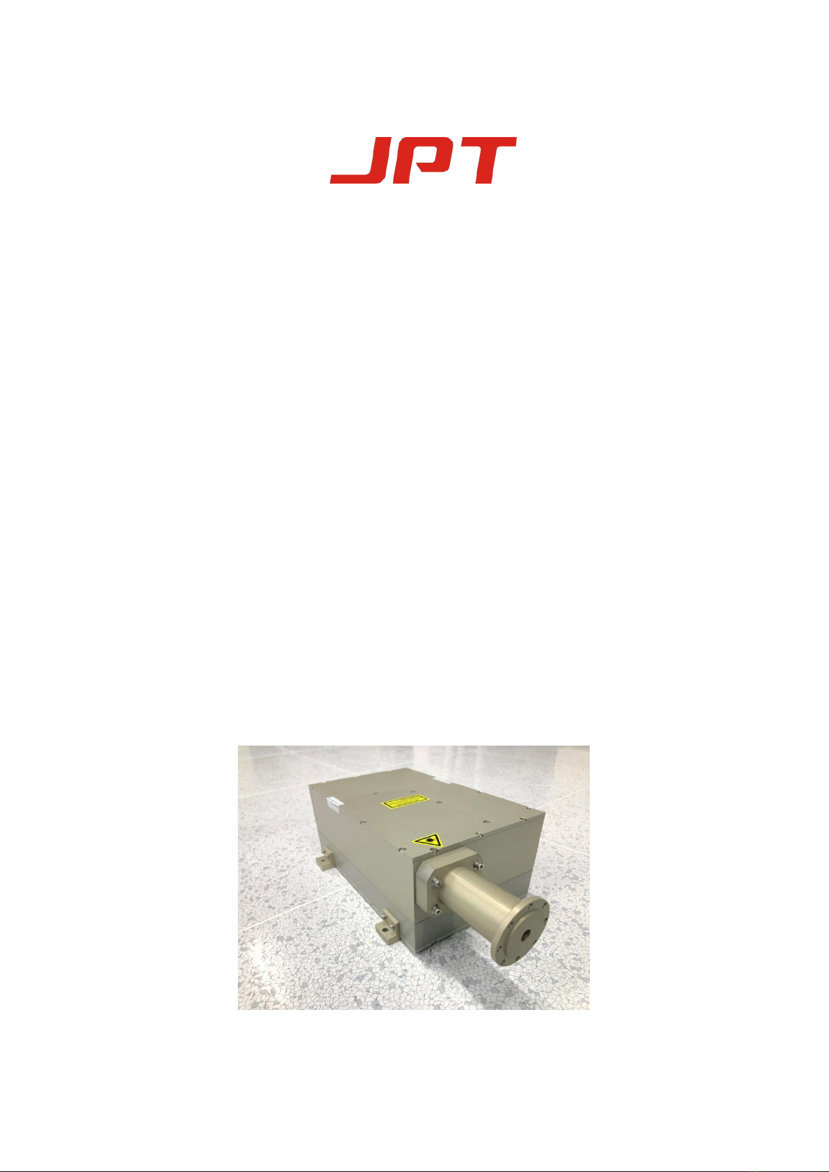
JPT made Seal-355-3/5 series UV laser are end pump solid state laser. Stable and compact
resonator design makes higher laser efficiency, good beam quality and high stability. Long
lifetime and maintenance free. The chamber inner LD design, reduced the fiber interference.
The new design of AIO, it’s space saving and has a stronger anti-interference capability.
Seal-355-3/5S is a member of Seal family. The laser of this series has excellent beam quality (M2
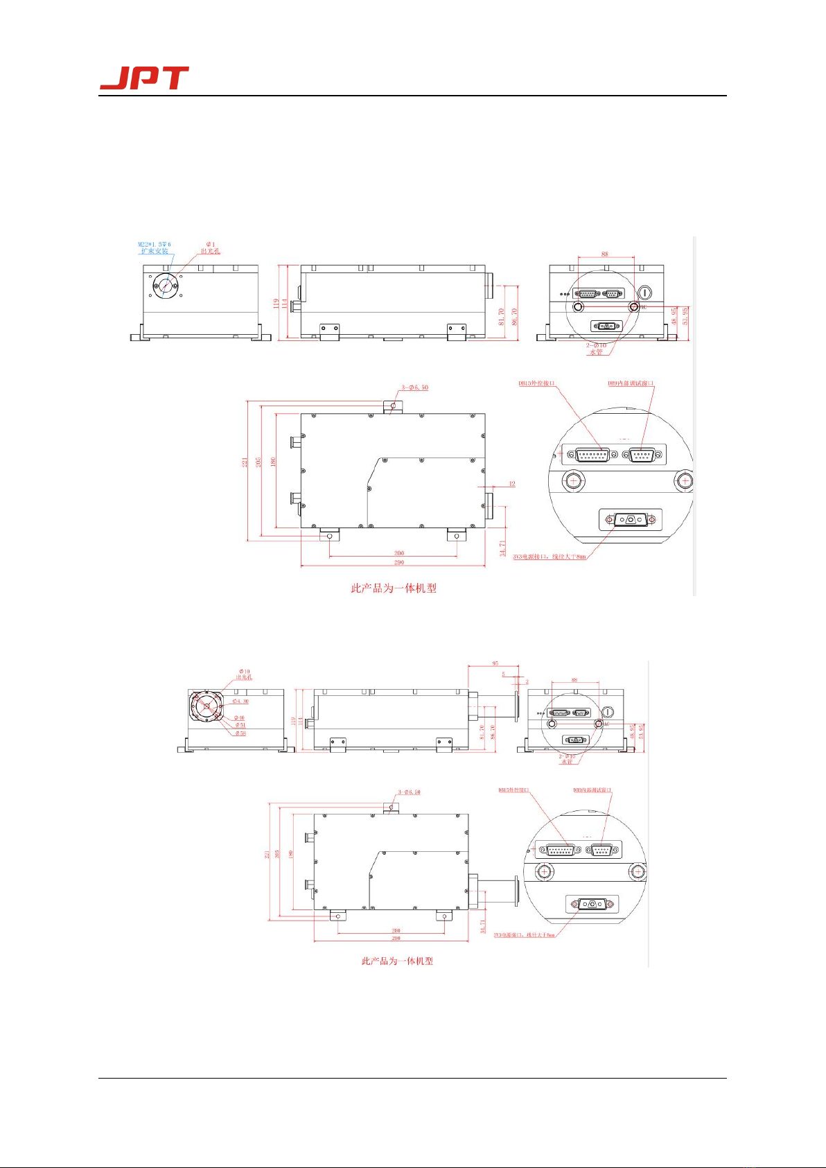
< 1.2) and perfect spot characteristics (circularity>90%). The whole machine adopts an
integrated structure design, which combines the optical and external driving circuit, making the
product series have strong anti-interference ability. Optimize and upgrade the fully sealed
structure to effectively prevent the entry of external dust. At the same time, the isolation of
external water molecules makes the whole machine have a strong anti-moisture characteristics,
making the Seal series can adapt more harsh industrial environments. In addition, the service
life can be greatly prolonged by introducing a self-cleaning system for intracavity As an
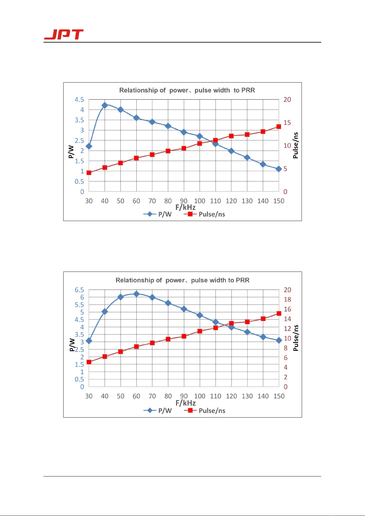
upgraded version of Seal-355-3/5, the output laser of Seal-355-3/5S series ultraviolet solid-state
lasers has very short pulse width (<10ns@60KHZ) and excellent pulse stability (<3%
RMS@60KHZ) at medium and high repetition frequencies.

Seal-355-3/5 User manual
2
1.2 Technical parameter
Laser parameter
Parameter List
Laser Type
3W UV-AIO
5W UV-AIO
3W UV short pulse
width
5W UV short pulse
width
Model Number
Seal-355-3
Seal-355-5
Seal-355-3-S
Seal-355-5-S
Wavelength
355nm
Mean Power
>3W@30kHZ
>5W@40kHZ
>3W@40kHZ
>5W@60kHZ
Pulse Duration
<15ns@30kHz
<15ns@40kHz
<10ns@40kHz
<10ns@60kHz
Frequency Range
20KHz-2000KHz
30KHz-200KHz
Spatial Mode
TEM00
Beam Quality(M2)
M2≤1.2
Beam Circularity
>90%
Beam Full
Divergence Angle
≤2mrad[1]
Beam Diameter
Without expander 0.7±0.1mm[2]
Polarization Ratio
>100:1
Polarization
Orientation
水平/Horizontal
Average Power
Stability
RMS≤3%@24hr
Pulse-to-Pulse
Stability
RMS≤3%@30KHz
Operating
Temp.&RH
10℃~40℃;<80%
Storage
Temp.&RH
-15℃~50℃;<90%
Cooling Mode
Water-cooling
Electricity
Requirement
DC12V
Average Power
Consumption
300W
350W
300W
350W
Three-Dimensional
Size
302mm*180mm*114mm(L* W* H)
weight
9.26kg
[1]The beam of window film, not through the beam expander.
[2]The measuring area is the laser output window film.

Seal-355-3/5 User manual
3
Diagram of Seal-UV-3
Diagram of Seal-UV-5

Seal-355-3/5 User manual
4
Diagram of Seal-UV-3-S
Diagram of Seal-UV-5-S

Seal-355-3/5 User manual
5
2 Installation
2.1 Installation dimension
Figure1(a)Laser installation dimension without expander
Figure1(b)Laser installation dimension with expander

Seal-355-3/5 User manual
6
2.2 Installation
1)Using screw to fix the laser head on the supporting
structure.
2)Connect the chiller water pipe to laser, make sure no leakage。
3)Connect the power supply and fasten.

Seal-355-3/5 User manual
7
4)Connect the DB15 to the laser and make sure it’s tight. Another side connect to the card.
5)For the convenience of customers, the Seal-355 equip a set of expander devices (including
a 10 times expander and a installation sleeve), If the customer doesn’t need this devices,
they can disassemble it like the following step.

Seal-355-3/5 User manual
8
*Special statement:The expander and the sleeve are not covered by the warranty.
3. GUI control and interface
3.1 GUI interface
The function of GUI control is internal debugging and monitoring. All parameters have been
debugged before ship out. Therefore, the customer does not need this software. Customers
only need to ensure that the external control signals are properly connected, and can be
used easily according to the correct operation.

Seal-355-3/5 User manual
9
Figure2 GUI function explanation
NO
Name
Description
1
ADJ
Q Switch pulse width change the laser power
2
PRF
Q SWITCH frequency
3
IS
Adjust current value(suggest no adjustment at customer side)
4
MODE
choose Q-switch trigger mode, the default mode is external control
5
QS
On is Q-switch mode, off is CW mode
6
DIODE
Pump current switch
3.2 Interface Explanation
Laser interface
*Indicator light
Red light Temperature alarm, When the temperature of LD is abnormal or the water temperature is
abnormal, it will light up. Should cut off the power of laser immediately and find the issue.
Yellow light When the laser works well, it will show this light.
Green light The LD and laser works well.

Seal-355-3/5 User manual
10
DB15 Pinout
Pin
Type
Definition
Description
Comment
1~5
Reserve
N/A
N/A
N/A
6
Input, Digit
GATE
Laser on
High;Guide beam Low:Laser
5V TTL input
7
Input, Digit
TRIGGER
Modulation
5V TTL input
8
Input, Digit
FPS
First pulse killer
External marking card provide, TTL
9~13
Reserve
N/A
N/A
N/A
14~15
Ground, Digit
GND
The GND for PIN6/PIN7/PIN8
4.Laser control
4.1 Control mode
The laser emission/off is controlled by Gate signal;laser frequency、power and other
Parameter setting is through PWM signal,change PWM frequency and duty cycle。Duty cycle:
out put PWM signal,high voltage time and PWM period ratio. For example:PWM frequency
is50KHZ,the period is20μs,if high voltage time is6μs,Then the low voltage time is 14μs,
to get ratio 6:20,the PWM duty cycle is 3:10.
In certain frequency condition, laser PWM signal high voltage 1 us relate to ADJUST=100%,
means This frequency related largest power, smallest pulse width, peak power, if
increase high voltage related pulse width( reduce ADJUST), this frequency laser power
reduce, pulse width increase.
Through PWM signal(to Q-switch)frequency、duty cycle adjustment could control laser pulse
frequency, power and pulse width.

Seal-355-3/5 User manual
11
4.2 Control timing
When the laser is in the external control mode, it could control the laser output, frequency
and PWM (pulse width modulation)by external signal.
In order to control the laser, it needs the correct timing signal for control card. When the
laser works, the GATE corresponds to the Laser and the TRIG corresponding to the PWM.
Need the following timing.
4.3 Convert card connection
Connect instruction: ①The left PIN to marking control card.
②The right DB15 connector to DB15 cable for laser.
Figure5 Convert card

Seal-355-3/5 User manual
12
1. Convert card VCC +5V to marking control card VCC +5V; Convert card GND to marking
control card GND.
2. “Laser” on convert card means the input laser on signal is the same polarity as the GATE,
“Laser
” means the input laser on signal is the converse polarity as the GATE. When the
laser on signal to “laser”, use the short cap short circuit PIN2 and PIN3 of J1. When the
laser on signal to “Laser
”, use the short cap short circuit PIN1 and PIN2 of J1.
3. “PWM” on convert card means the input modulation signal is the same polarity as the
TRIG, “ PWM
” means the input modulation signal is the converse polarity as the TRIG.
When the modulation signal to “PWM”, use the short cap short circuit PIN2 and PIN3 of
J2. When the modulation signal to “PWM
”, use the short cap short circuit PIN1 and PIN2
of J2.
4. “FPS” on convert card means the input first pulse killer signal is the same polarity as the
FPS, “ FPS
” means the input first pulse killer signal is the converse polarity as the FPS.
When the first pulse killer signal to “FPS”, use the short cap short circuit PIN2 and PIN3 of
J3. When the first pulse killer signal to “ FPS
”, use the short cap short circuit PIN1 and
PIN2 of J3.
When the FPS function is not enable, kindly short circuit the PIN1 and PIN2 of J3

Seal-355-3/5 User manual
13
4.4 Control card connection
1) JCZ card
A kinds of JCZ card
PIN12 to LASER﹢and short circuit
PIN2, PIN3 of J1
PIN22 to PWM﹢and short circuit
PIN2, PIN3 of J2
B kinds of JCZ card
PIN24 to LASER- and short circuit
PIN1, PIN2 of J1
PIN13 to PWM+ and short circuit
PIN2, PIN3 of J2
C kinds of JCZ card
PIN15 to LASER- and short circuit
PIN1, PIN2 of J1
PIN14 to PWM+ and short circuit
PIN2, PIN3 of J2

Seal-355-3/5 User manual
14
2) SAMlight card
5. Operation
5.1 Turn on laser
1)connect chiller with laser water connector,lock tight.
2)Turn on chiller,set temperature at 25℃,until stable at 25±0.5℃
3)check laser outlook condition,if any particle/sticker block output port, please remove it.
4)
Make sure laser controller and laser head properly connected, check if marking system and
laser System been connected properly.
5)Switch on 12V DC power supply, turn on the key switch(before operation, we must connect
the control card and ensure that the card has been supplied to prevent laser damage).
Confirm there is no abnormal indicator, and wait for the laser to get stable then we can use
SAMlight card
PIN31 to LASER- and short circuit
PIN1, PIN2 of J1
PIN13 to PWM﹢and short circuit
PIN2, PIN3 of J2

Seal-355-3/5 User manual
15
the laser to mark.
*When laser temperature abnormal, the protection will lock the laser, please check if
chiller is running or the power cable is connected properly.
5.2 Turn off laser
1)Stop the processing.
2)Turn off key switch.
3)Turn off power supply.
4)Turn off the chiller.
5.3 Attention when operate laser
1)suggest to wear Laser safety glasses all the time;
2)Stop marking, then off the laser.
This manual for user operation purpose ,official service and warranty will
Follow the actual sales contract and terms and condition. Thanks four your
support.
This manual suits for next models
3
Table of contents
Other JPT Measuring Instrument manuals