- 9 -
SECTION 6 SPECIFICATIONS
Receiver type: Multichannel (12CH, SBAS 1CH) all in view
Accuracy: 13m 2DRMS (C/A code, HDOP≦4, SA off)
7m 2DRMS (SBAS corrected)
0.1knots RMS (steady state)
Geodetic datum: 46 (selectable, default*: WGS-84)
Data input: Initial input,
GPS correction data (RTCM SC-104 ver.2.0, Type 1,2,7,9)
Data output: IEC61162-1 or NMEA0183 compliance
(selectable, default*: NMEA0183 ver.1.5)
IEC61162-1 (NMEA0183 ver.2.3)
GGA, RMC, VTG, ZDA, DTM, GBS, GNS
NMEA0183 ver.2.1 GGA, RMC, GLL, VTG, DTM
NMEA0183 ver.1.5 GGA, RMC, GLL, VTG
Operating temperature: -25℃ to +70℃
Storage temperature: -40℃ to +85℃
Vibration: IEC60945 compliance
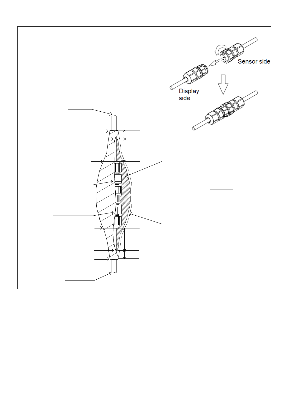
Waterproof: IEC60945/USCG CFR-46 compliance
EMC: IEC60945 compliance
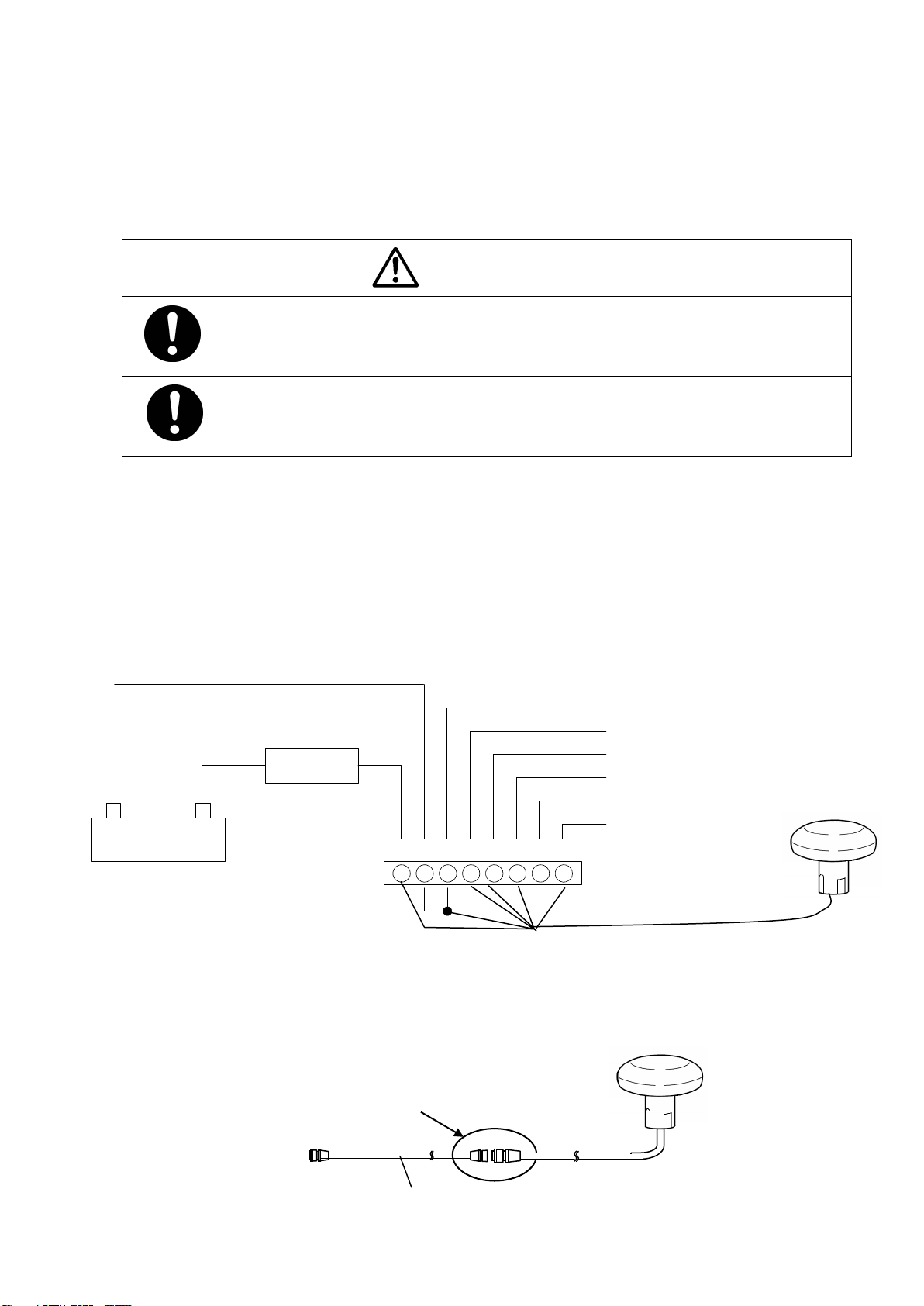
Input voltage: 12/24VDC +30%, -10%
Power consumption: Less than 1.5W
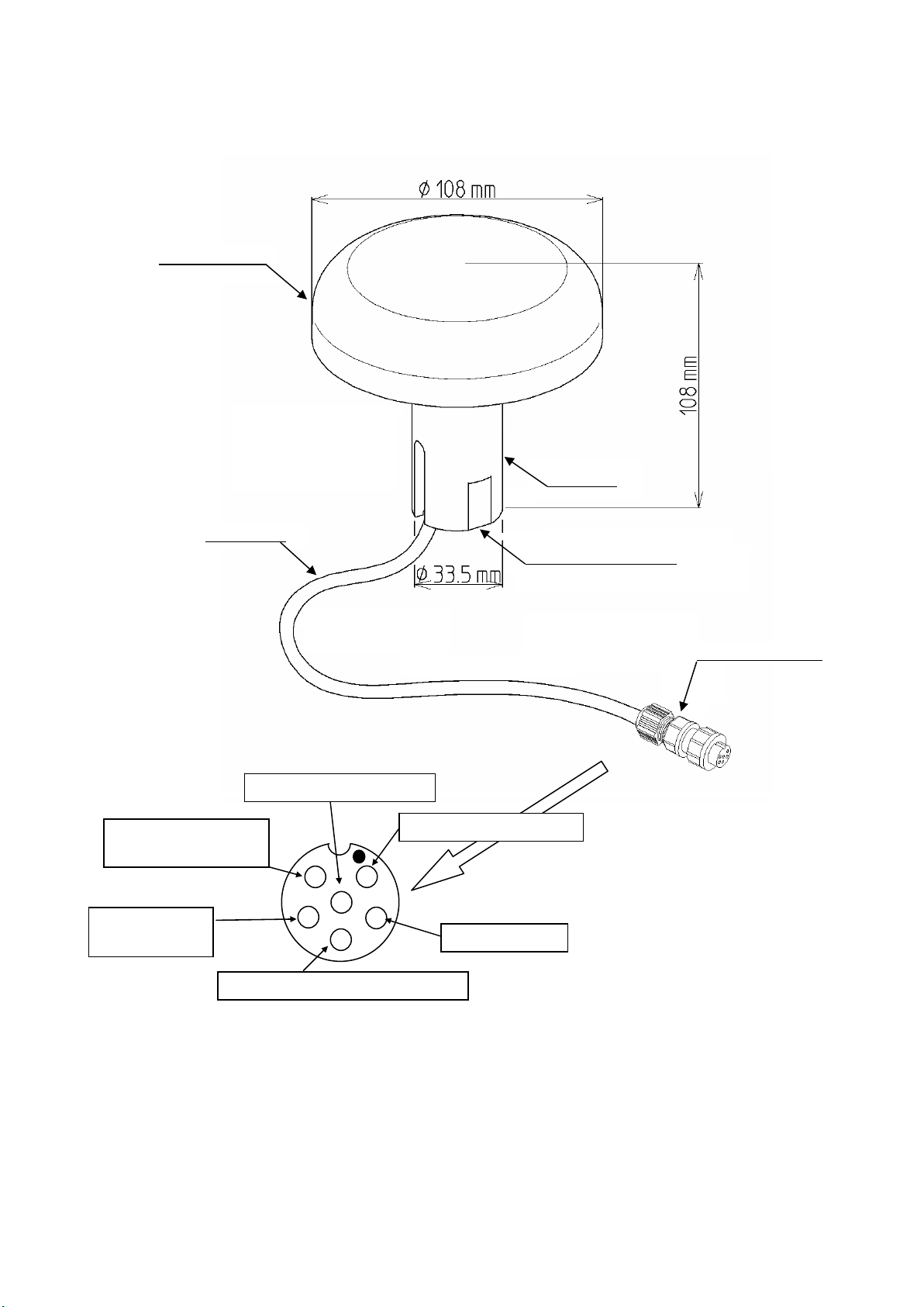
Dimensions, Mass: 108H×108φ(mm), less than 0.7kg
* When the Lithium battery runs out, the settings are restored to the default values. In addition, it will take about a
minute for position fix. The battery life expires in about 10 years under the normal use condition, but it may differ
depending on the environment or use conditions.