JUKI DDL 552 User manual

MODEL
DDL-552
-553
-555
HIGH
SPEED
SINGLE
NEEDLE,
LOCK
STITCH
INDUSTRIAL
SEWING
MACHINE
Instruction
Book
TOKYO
JUKI
INDUSTRIAL
CO.ITD
From the library of: Superior Sewing Machine & Supply LLC

We
thank
you
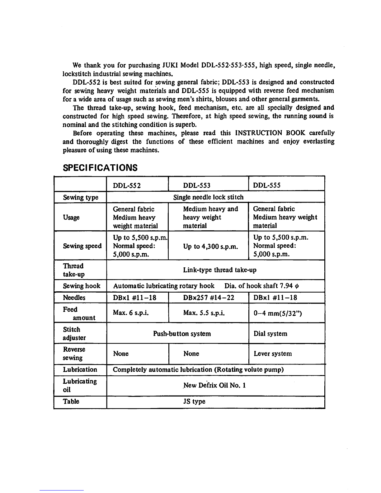
for purchasing JUKI Model DDL-552-553-555, high speed, single needle,
lockstitch
industrial
sewing machines.
DDL-SS2 is best suited for sewing general fabric; DDL-S53 is designed and constructed
for sewing heavy weight materials and DDL-555 is equipped with reverse feed mechanism
for a wide area of usage such as sewing men's shirts, blouses
and
other
general garments.
The thread take-up, sewing
hook,
feed mechanism, etc. are all specially designed
and
constructed for high speed sewing. Therefore, at high speed sewing, the running sound is
nominal
and
the
stitching
condition
is superb.
Before operating these machines, please read this INSTRUCTION BOOK carefully
and thoroughly digest the functions of these efficient machines and enjoy everlasting
pleasure
of
using these machines.
SPECIFICATIONS
DDL-552
DDL-553
DDL-555
Sewing
type
Single needle
lock
stitch
Usage
General
fabric
Medium
heavy
weight
material
Medium
heavy
and
heavy
weight
material
General
fabric
Medium heavy weight
material
Sewing
speed
Up to
5,500
s.p.m.
Normal speed:
5,000
s.p.m.
Up to
4,300
s.p.m. Up to
5,500
s.p.m.
Normal
speed:
5,000
s.p.m.
Thread
take-up
Link-type
thread
take-up
Sewing
hook
Automatic
lubricating
rotary
hook
Dia.
of
hook
shaft
7.94
<l>
Needles
DBxl
#11-18
DBx257
#14-22
DBxl
#11-18
Feed
amount
Max. 6 s.p.i. Max. 5.5 s.p.i.
0-4
mm(5/32")
Stitch
adjuster
Push-button
system
Dial
system
Reverse
sewing
None
None
Lever
system
Lubrication
Completely
automatic
lubrication
(Rotating
volute
pump)
Lubricating
oil
New
Defrix
Oil
No.
1
Table
JS
type
From the library of: Superior Sewing Machine & Supply LLC

TABLE
OF
CONTENTS
(DDL-552-553-555)
Page
Installingthe oil reservoir 2
MotorpuUey and the belt 2
Cautions on operating the machine 3
Lubrication 3
1.
Adjusting
theoil
supply
to the
face
part 4
2. The
oU
adjusting pin 4
3.
Adjusting
theoil
supply
to thehook
components
4
Threading the machine 5
Preparation
of
the bobbin thread 6
Inserting & removing the bobbin case 6
Windingthe bobbin thread 6
How to insert the bobbin 6
The thread tension 7
Adjusting the needle thread tension 7
Thread take-up spring 7
Adjusting the bobbin thread tension 7
Presserfoot and feed dog 8
Adjusting the pressure
of
the presser foot 8
The
presser
foot
hand
lifter
8
Height of the feed dog 8
The stitch length 9
Adjusting
the stitch
length
(DDL-552-553)
9
Adjusting
the stitch length
(DDL-555)
9
Reverse
sewing
(DDL-555)
9
Inserting
the
needle
Installing
and
removing
the
sewing
hook
Relation
between
thehookandtlie
needle
Adjusting
the
height
of the
presser
bar
Adjusting
the
amount
ofthe
thread
take-up.
Adjusting
the
pressing
pressure
of the
feed
lever
(DDL-555)
12
(Note)
Due to improvements on the machine, some parts of the operational procedures
of this INSTRUCTION BOOK might be changed without notice.
- 1 -
From the library of: Superior Sewing Machine & Supply LLC

INSTALLING
THE
OIL
RESERVOIR
Rubber
cushion
Oil
reservoir
Operator
side
Hinge side
As shown in the flgure, set the reservoir in
such a way so that the 4 comers
of
the grooV'
ed part of the table will be supporting the
reservoir.
1.
Nail
in
the
2
rubber
cushions
in
front
to
the protruding
part
of
the table.
2. Place the oil reservoir on the protruding
part
of
the
table.
MOTOR
PULLEY
AND
THE
BELT
V-belt
Motor
pulley
Model DDL-552 can sew at a high speed of
up to 5,500 s.p.m., DDL-553 at a high speed
of up to 4,300
s.p.m.
and
DDL-555
at a speed
of up to 5,500 s.p.m. For all of above models,
use a 3-phase
400
W(l/2
HP)
clutch
motor
when connected directly to the power source.
Use a M
type
V-belt.
The
relation
between
the
number
of
rotation
of
the
machine
with
the dimension of the
motor
pulley is shown in
the
table. (Effective diameter)
* The effective diameter of the motor pulley
means
the
diameter
as
measured
from
the
center
of
the
V-belt
when
the
belt
is
wound
around
the
machine.
Model
Cycle
No.
of
rotation
of
machine
Part
No.
of
motor
pulley
Effective
diameter
of
motor
pulley
DDL-552
DDL-555
50
5.060
s.p.m.
4,630
s.p.m.
MTK-PVl
20000
MTK-POllOOOO
120mm(4-47/64")
110mm(4-5/16")
60
5,040 s.p.m.
4,540
s.p.m.
MTK-PVl
00000
MTK-PV090000
100mm(3-15/16")
90mm(3-3/4")
DDL-553
50
4,250
s.p.m.
3,850
s.p.m.
MTK-PVl
00000
MTK-PV090000
100mm(3-15/16")
90mm(3-35/64")
60
4,320
s.p.m.
3,790
s.p.m.
MTK-P0085000
MTK-P0075000
85mm(3-ll/32")
75mm(2-61/64")
- 2 -
From the library of: Superior Sewing Machine & Supply LLC

CAUTIONS
ON
OPERATING
THE
MACHINE
1
Do
not run the
machine,
under
any
circumstances,
before
theoil
reservoir
is
filled
up
with
fresh
oil.
2. Always rotate the machine toward the operator. Do not run the machine in the re
verse
direction.
3.
Although
the
machines
can
attain
a
maximum
speed,
for
the
first
month
drop
the
speed
to
normal
speed
and
for
DDL-552
operate
at a
normal
speed
of
4,500
s.p.m.,
for
DDL-553
at
3,800
s.p.m.
and
for
DDL-555
at
4,500
s.p.m.
After
that,
run
the
machines
at an
appropriate
speed
depending
on the
nature
of
work
and
the
capability
of
the
operator.
LUBRICATION
HIGH
mark
Oil
reservoir
LOW
mark
Before
operating
the
machine
1. Fill up the oil reservoir with JUKI New
Defrix Oil No. 1 up to the mark "HIGH".
2.
Watch
and
see
that
the
oil level
does
not
go
below
the
"LOW"
mark.
Oil sight window
3.
Under
normal
conditions,
when
the
machine
is
run
after
it is filled up with oil,
the
oil will
spurt
against
the
oil sight window.
(Caution)
1) When the oil gets dirty, change it with new,
fresh oil.
If
the oil plug
of
the reservoir is
removed,
oil will
come
out.
2)
When
the
machine
is
to
be
run
for
the
first
time or when it was idle for a great length
of
time,
run
the
machine
at
3,000-3,500
s.p.m.
for
about
10
minutes
and
allow
the
machine
to
get
well-oiled.
3) When
the
machine
is
to
be
run
constantly
at less than
3,500
s.p.m. adjust so
that
the
oil supply to various parts be increased.
IDOL-SSS
H
•mtrm ntTffI
- 3 -
From the library of: Superior Sewing Machine & Supply LLC

Oil
adjusting
pin
Oil
amount
gets
less
Crank
II•
••
''
1^
Oil
amount
gets
more
n I I II
If
11
Needle
bar
crank
Groove
of
eccentric
"Oil
adjusting
pin
Arm
shaft
^
Oil
adjusting
pin
screw
Counterweight
Z\
Oil regulating valve
1. Adjusting the oil supply to the face
part
When adjusting the oil supply to the thread
take-up and needle bar crank components,
remove
the
face
plate
and
the
oil preventing
plate and adjust by turning the oil adjusting
pin at the tip of the main
shaft
1. When
the
red
mark
of
the adjusting pin
comes
near
the
crank,
the
oil
amount
gets
less.
2. When
the
red
mark
comes to
the
opposite
side
of
the
crank,
the
oil
amount
gets
more.
(Caution)
The
oil
amount
does
not
change
Immediately
after
the
adjustment,
so
when
adjusting,
have
this
in
miiid.
2.
The
oil
adjusting
pin
1.
2.
The oil adjusting pin has a carved groove
as shown in the figure. When this groove
and
the
oil
hole
of
the
main
shaft
come
together, the oil amount gets more.
When
the
groove
is at the oppositesideof
the oil hole, the oil
amount
gets less.
The
red
mark
on
the
oil adjuster shows
the
side
without
the
carved groove.
3. Adjusting
the
oil supply
to
the
hook
components
The
supply
of
oil to
the
hook
components
can be adjusted by
the
oil regulating valve on
the
hook
shaft.
1. If this
valve
is turned toward0
side(right),
the
oil
amount
gets
more.
2. If this
valve
is turned
to0
side(left), the
amount
gets less.
- 4 -
From the library of: Superior Sewing Machine & Supply LLC

THREADING
THE
MACHINE
Rotate
the
hand
wheel
to
right
and
place
the
thread
take-up
to
the
highest
position.
1.
Pass
the
needle
thread
in the
order
shown
by the
flgure.
2.
Pass
the
thread
to the
needle
eye
from
left to
right.
3.
Pull
out about 10
cni(4")
of the
thread
from
the
needle
eye.
(U)
- 5 ~
From the library of: Superior Sewing Machine & Supply LLC

PREPARATION
OF
THE
BOBBIN
THREAD
Bobbin
case
Trip
latch
Hook
Tension
disc
base
Adjusting screw
— ^
Thread
hole
Hfii\
f(l!r
Thread
passinghole
Inserting &removing
the
bobbin
case
1.
Rotate
the
hand
wheel
with
your
hand
and
bring the needle to its highest position.
2.
Tilt
the machine and support it by tlie head
support
on the table.
3. Lift up the knob of the bobbin case and
take
it
out.
*
If
you
hold
the
knob
in
open
condition,
bobbin
will
not
fall
off.
4.
To
insert
the
bobbin
case,
insert
it
deep
into
the
shaft
of
tlie
hook
so
that
the
nose
of
the
bobbin
case fully
enters
the
groove
of
the
hook
and
then
close
the
knob.
Winding
the
bobbin
thread
1.
Set
the
bobbin
winder
to
the
table
with
screws.
2.
Pass
the
thread
in
the
order
shown
in
the
figure and wind it around the bobbin
several
times.
3. Knock down the trip latch and contact the
pulley to the
belt
4. Adjust the winding amount by the winding
adjustingscrewso that about 80%iswound.
5.
When
the
thread
is
wound
unevenly,
move
the
thread
tension
disc
base
to
left
and
correct
to
even winding
condition.
6. When the winding is completed, the trip
latch
will be released
and
the
pulley will
stop
automatically.
How
to
insert
the
bobbin
1.
Hold
the
bobbin
and
insert
it
to
the
bobbin
case so
that
the
thread
will be in
ri^t-twist
condition.
2. Pass the
thread
to
the
thread passing hole
of
the
bobbin
case.
3.
Then
pull the
thread
and
it
will pass under
the
thread
tension spring and
can
be pulled
out
through
the
thread
hole.
- 6 -
From the library of: Superior Sewing Machine & Supply LLC

THE
THREAD
TENSION
Weaker
Stronger
Adjusting
the
needle
thread
tension
Ideal
stitches
are
formed
when
the
needle
thread and the bobbin thread are perfectly
interlocked
at
the
center
of
the
cloth.
The tension of the needle thread is adjusted
by
the
thread
tension
nut.
1. Turn it to right to make the tensionstronger
and
to
the
left
to
make
it
weaker.
Thread take-up spring
* To change the moving range of the thread
tension spring:
1.
Loosen
the
screw
of
the
thread
tension
bracket.
2.
Rotate
the
thread
tension
bar.
» To change the strength
of
the thread take-
up spring.
1. Loosen the set screw, remove the thread
tension
bar.
2.
Loosen
the
thread
tension
bar
set
screw
and
adjust.
3.
When
the
thread
tension
bar
is
turned
to
right, the spring will get stronger and if
turned
to
left,
it will
get
weaker.
Thread
tension
bar
set
screw
'-'Thread
tension
nut
Ehread
take-up
springy
Movingrange
(Tl^ad
tension
bar
bracket
set
screw , / /
Adjusting screw
Thread
take-up spring
Adjusting
the
bobbin
thread
tension
Rotate
the
thread
tension screw
of
the
bobbin
case
to
adjust
the
bobbin
thread
tension.
1. Rotate it to right to make the bobbin
thread tension stronger and to left to make
it
weaker.
_ 7 -
From the library of: Superior Sewing Machine & Supply LLC

PRESSER
FOOT
AND
FEED
DOG
Pressure
adjusting
screw
Nut
—
0
Hand
hfter
Hill
"
JUKI
N!|^
Feed driving fork
~T7=
Clamp
screw*"
lU
Adjusting
the
pressure
of
the
presser
foot
1.
Turn
the
pressure adjusting screw
to
right
to
make
the
pressure
stronger.
2.
Turn
this
screw to
left
to make
the
pressure
weaker.
Normal pressure
for
general fabric is
about
5 kg (11 lbs).
3.
After
adjustment,
firmly tighten the
nut.
The
presser
foot
hand
lifter
To stop the presser
foot
at
the
lifted position:
1.
Rotate
the
hand
lifter
in
the
rear
of
the
face
part
either
to
right or left.
2. The presser foot will go up
about
5 mm
(13/64")
and
stops.
3. To
lower
the
presser
foot,
activate
the
knee
lifter
once
and
the
presser
foot
will
come
down
to
the
original position.
4. With
the
knee
lifter,
the
presser
foot
will
go up
about
10 mm
(25/64")
Height
of
the
feed
dog
The height of the feed dog from the surface
of
the
throat
plate
is set
from0.7-0.8mm(l/32").
In sewing light weight materials, if this height is
too
high, shrink-stitching
may
result.
To
adjust
the
height
of
the
feed dog:
1.
Loosen
the
clamping screw
of
the
feed
driv
ing
fork
of
the
compound
feed.
2. Move the feed dog base up and down and
adjust
3. After adjusting, tightly tighten the clamping
screw.
0.7~0.8om
- 8 -
Feed
dog Throat plate
From the library of: Superior Sewing Machine & Supply LLC

THE
STITCH
LENGTH
Feed
adjusting dial
t
Feed
lever
I
1.DDI--S5SJ
Adjustingthe stitch length
(DDL-552-DDL-553)
The stitch length
of
DDL-552
and
DDL-553 is
adjusted by the push button ® at the center
of
the upper surface of the arm. Rotate the
hand wheel as you keep pressing down the ®
button.
When the button drops down deep into the
groove of the ratchet (you can feed it) push
down the button further and by rotating the
hand wheel, match the
number
of stitches
wanted
(D with the indicator® of the
frame.
With this, the length of stitches can be obtained.
The figures on the
hand
wheel indicate
the
number
of
stitches per one inch. Release the
push
button
and
verify
that
the
button
returns
to the original position.
The maximum stitch length for DDL-552 is
6 s.p.i. and for DDL-553is 5.5 s.p.i.
Reverse sewing can
not
be done.
(Caution)
Do
not
touch
the
button
while
the
machine is running.
(DOL-555)
The stitch length of this model can be adjusted
by rotating the feed adjusting dial on top of
the
feed
lever.
The figures on the graduation scale is shown in
millimeter
(mm).
1. Rotate the feed adjusting dial
either
to
right
or
left
and
2. Match the wanted figure with the pin
coming
out
from
the
frame.
* The maximum stitch length is 4mm(5/32").
Reverse sewing
(DDL-555)
1. For reverse sewing, push the feed lever
down.
2. As long as this lever is kept down, reverse
sewing can be
performed.
3.
Release
this
lever
and
the
feed
lever
will
re
turn
to original position and normal straight
stitching can be resumed.
- 9 -
From the library of: Superior Sewing Machine & Supply LLC

INSERTING
THE
NEEDLE
Set
screw
Needle
Groove
For
DDL-552
and
DDL-555
models,
use
DBxl
needles
and
for
DDL-553
model,
use DBx2S7
needle.
There
are
many
size
numbers
of
needles
but size numbers depend on the thickness of
the using thread or the kinds of sewing cloth.
So, select a correct size and number for your
work.
1.
Rotate
the
hand
wheel
and
bring
the
needle
bar
to the highest position.
2. Loosen
the
needle clamp screw.
3. Hold the needle so
that
the long groove of
the
needle
comes
to
your
left
side.
4. Insert the needle deep into the needle hole.
5. Then securely tighten the needle clamping
screw.
INSTALLING AND REMOVING
THE
SEWING HOOK
r
Set
screw
Bobbin case
positioning
finger
screw
During the running of the machine, if thread
hards get into the hook or the position of the
hook changes for some reason or to exchange
the
hook
with
a
new
one,
do as follows in
order:
1.
Rotate
the
hand
wheel and bring the needle
bar
to
the
highest position.
2.
Remove
the
bobbin
case
and
the
needle.
3. Remove the bobbin case base positioning
finger set screw and take out the bobbin
case positioning finger.
4. Loosen the 3 screws
of
the sewing hook.
5.
Rotate
the
hand
wheel
and
raise up
the
feed base to its highest position.
6.
Rotate
the sewing
hook
with
your
hand
and
place it in
the
position as shown in
the
figure.
7. Pull
the
hook
to
your
left
and
take
it
out.
*
To
install
the
hook
back,
reverse
this
procedure.
-10
From the library of: Superior Sewing Machine & Supply LLC

RELATION
BETWEEN
THE
HOOK
AND
THE
NEEDLE
Clamp screw
(D
DETERMINE
THE
HEIGHT
OF
THE
NEEDLE
BAR
^ Needle bar
lower
bushing
Upper
indicating
line
Lower
indicating
line
Needle
bar
(D
DETERMINE
THE
POSITION
•
OF
THE
SEWING
HOOK
Needle
Biade
pointy
the
sewing,
hook
Lower
indicating
line
(At
this
position,
match
the
blade
point
of
the
sewing
hook
with
the
center
of
the
needle)
Sewing
hook
Match
the needle with the
sewing
hook as
follows:
1. Rotate the hand
wheel
andbringthe
needle
bar to its lowest position.
2.
Loosen
the needlebar
clamping
set
screw.
(Note)
When
matching the timing of the needle and
the sewing hook, be sure to set the feed,
adjusting dial to
"0".
(Determine
the
height
of the
needle
bar)
3. Match the upper carved line of the needle
bar with the lower edge of the needle bar
lower bushing.
4.
Tighten
the needlebar
clamping
set
screw.
(Determine
the position of the
sewing
hook)
5. Loosen the 3 clamping screwsof the hook
so that the hook can be rotated freely with
the
hand.
6. Place the
hook
with your hand to the thread
passing position.
7.
Rotate
the
hand
wheel
and
match
the
lower
carved
line
of
the
needle
bar
with
the
lower
edge of the needle bar lower bushing.
8. In this condition, match the blade point of
the
hook
with
the
center
line
of
the
needle.
9.
Make
the
clearance
between
the
needle
and the
hook
blade point td
O.OS
mpi
and
10.
Securely
tighten the hook
clamping
set
screw.
-
11
-
From the library of: Superior Sewing Machine & Supply LLC

ADJUSTING THE HEIGHT OF THE PRESSER BAR
Presser
bar
clamp
screw
When
the height or the direction of the
presser bar is to be changed due to the
exchange
of
presser foot:
1. Remove the rubber plug of the face plate.
2. From this hole, adjust by loosening the
presser bar clamping screw.
3. After the adjustment, securely tighten the
set
screw.
ADJUSTING THE AMOUNT OF THREAD TAKE-UP
^
Thread
guide
More
Less
r~/
The
amount
of
the
thread take-up should
be changed according to the length of stitches
or thickness
of
the
sewing
cloth
to
produce
ideal
thread
tension.
1. When sewing heavy weight materiab, move
the thread guide to your left.
The thread take-up amount of the take-up
gets
more.
2. When sewing light weight materials, move
the
thread
guide to
your
riglit.
The thread take-up amount gets less.
ADJUSTING
THE
PRESSING
PRESSURE
OF
THE
FEED
LEVER
(DDL-555)
The reversing spring of the feed lever is
strengthened somewhat so
that
at high speed
sewing, no matter what kind
of
stitches are to
be
formed,
the
lever
returns
positively to
the
original
position.
When
the
stitching
pitch
is small or
when
the
machine is
to
be
run
by lowering
the
r.p.m.,
the pressing pressure of the feed lever can be
lessened
by
loosening
the adjusting nut
(T)
of
the accompanying figure.
-
12
-
From the library of: Superior Sewing Machine & Supply LLC

I
lllllll
TOKYO
JUKI
IIKVO
JUKI
INDUSTRIAL
G0..1T0.
Head
Office
&
Plant,
2-1,
8-chome,
Kokuryo
cho.
Chofu
shi.
Tokyo.
Japan
Business
Office:
23.
Kabuki
cho,
Sftiniuku
ku.
Tokyo.
Japan
Cable
Address:
JUKI
TOKYO
Telex:
232-2301
JUKISINJUK.U
TOK
^BEB
Printed
in
Japan
From the library of: Superior Sewing Machine & Supply LLC
This manual suits for next models
2
Table of contents
Other JUKI Sewing Machine manuals

JUKI
JUKI DDL-8700A-7 User manual

JUKI
JUKI HZL35Z-UL5 User manual

JUKI
JUKI PS-700 User manual

JUKI
JUKI AK118 User manual

JUKI
JUKI LU-562 User manual

JUKI
JUKI LU-2810ES-7 User manual

JUKI
JUKI DDL-9000A User manual

JUKI
JUKI IT-10 User manual

JUKI
JUKI MF-7500 Series User manual

JUKI
JUKI MEB-3810N Series User manual

JUKI
JUKI MO-6800S Series Quick start guide

JUKI
JUKI MF-7900-E11 User manual

JUKI
JUKI LU-2810-7 Series User manual

JUKI
JUKI MF-7923 User manual

JUKI
JUKI MO-735 User manual

JUKI
JUKI MO-735 User manual

JUKI
JUKI LS-341N User manual

JUKI
JUKI SC-810 User manual

JUKI
JUKI DDL-8700 User manual

JUKI
JUKI UnionSpecial 35800BLWG Setup guide