JUKI MO-6800S Series User manual

MO-6800S(D)/DD10 Series
INSTRUCTION MANUAL

i
CONTENTS
1. SPECIFICATION .............................................................................................................. 1
1-1. Specications of the sewing machine head ..................................................................................1
1-2. Specications of the control box .................................................................................................... 1
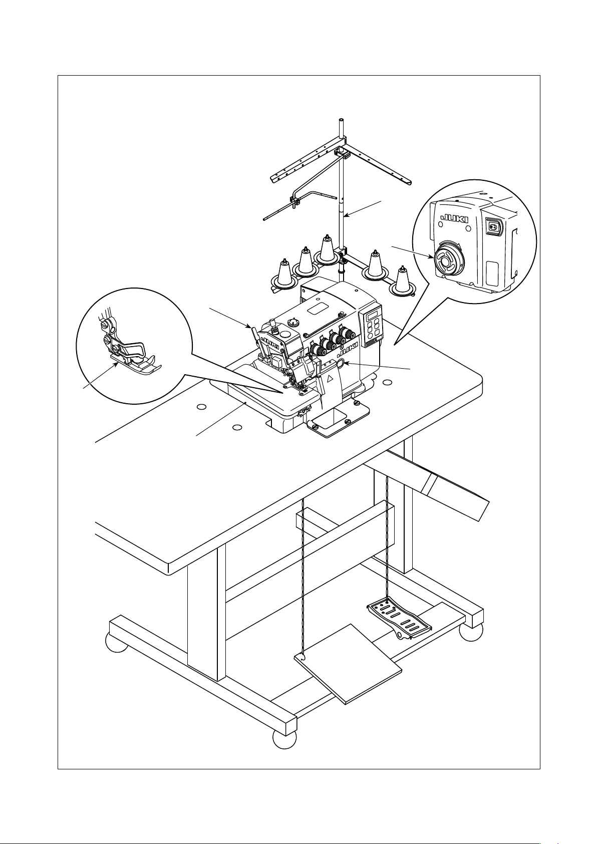
2. NAMES OF MAJOR PARTS............................................................................................ 2
3. INSTALLATION................................................................................................................ 3
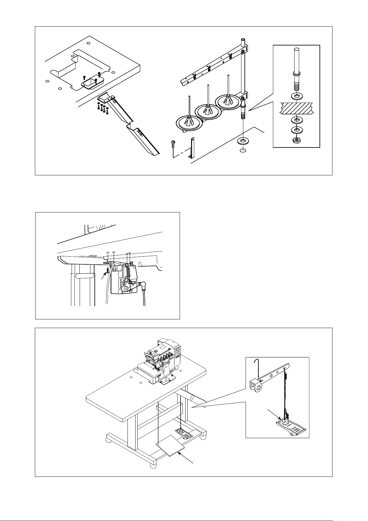
3-1. Installing the table and the table stand ..........................................................................................3
3-2. Installing the pedal sensor ..............................................................................................................4
3-3. Attaching the connecting rod..........................................................................................................5
3-4. Connecting the connector ...............................................................................................................6
3-5. How to install the power plug.......................................................................................................... 7
3-6. Power switch..................................................................................................................................... 7
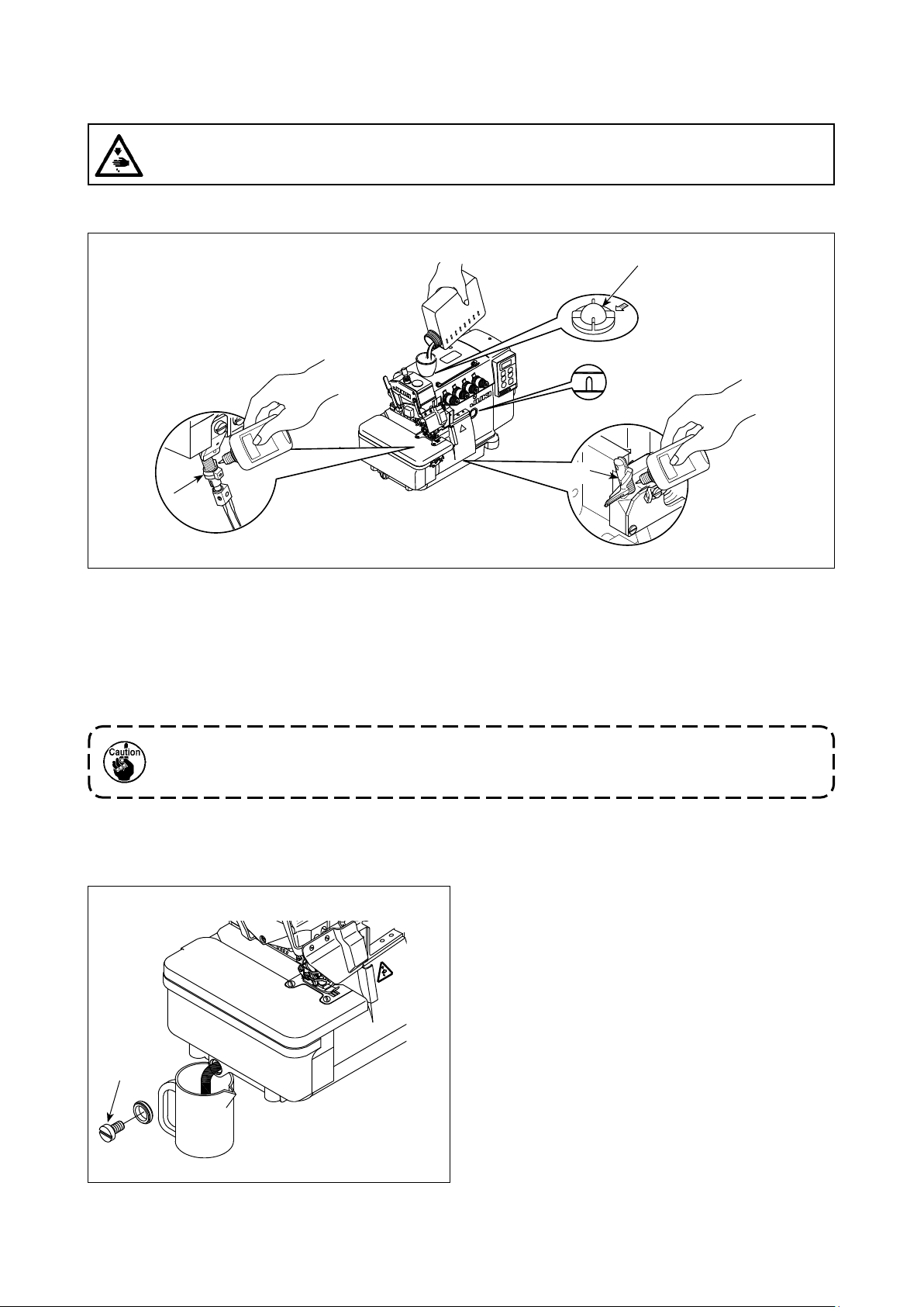
4. LUBRICATION AND DRAINAGE .................................................................................... 8
4-1. Lubrication oil ...................................................................................................................................8
4-2. Drainage and rell the oil................................................................................................................. 8
4-3. Exclusive grease replenishment (only for the MO-6800S).......................................................... 10
5. PREPARATION BEFORE SEWING .............................................................................. 11
5-1. Threading ........................................................................................................................................ 11
5-2. Adjusting the thread tension .........................................................................................................14
5-3. Replace the needle .........................................................................................................................15
5-4. Adjusting the stitch length.............................................................................................................16
5-5. Adjusting the dierential feed ratio ..............................................................................................16
5-6. Replace the knives .........................................................................................................................17
5-7. Adjusting the overedge width........................................................................................................18
5-8. Adjusting the needle height...........................................................................................................18
5-9. Adjusting the presser foot .............................................................................................................19
5-10. Adjusting the feed dog.................................................................................................................21
5-11. The relationship between the needle and the looper ................................................................22
5-12. Adjusting the amount of travel of the double chainstitch looper ............................................ 24
6. OPERATION PROCEDURE .......................................................................................... 25
6-1. Operation panel ..............................................................................................................................25
6-2. Font comparison table ...................................................................................................................26
6-3. Function setting.............................................................................................................................. 27
6-4. Function setting table ....................................................................................................................28
6-5. Details of setting of the main functions .......................................................................................32
6-6. Initialization of the function setting data...................................................................................... 34
6-7. Hand LED light ................................................................................................................................35
6-8. About the USB.................................................................................................................................36
7. MAINTENANCE............................................................................................................. 37
8. ADJUSTMENT DIMENSION VALUES .......................................................................... 38
8-1. Dimensions use to adjusting the looper and the needle guard .................................................38
8-2. Dimensions related to the position of the thread take-up and the looper thread cam
(standard adjustment)..................................................................................................................39
9. ERROR CODE LIST ...................................................................................................... 41
10. TABLE DRAWING ....................................................................................................... 42

– 1 –
MO-6804(D)/DD MO-6814S(D)/DD MO-6816S(D)/DD
Sewing speed Max. 7,000 sti/min (Excluding some subclass models)
Stitch length 0.6 to 3.8 (4.5) mm
Needle gauge - 2.0 mm 3.0, 5.0 mm
Overedge width * 1 1.5, 4.0 mm 3.0, 4.0 mm 4.0, 5.0, * 1 6.0 mm
Dierential feed ratio Gathering stitch1 : 2(Max. 1 : 4)
Stretching stitch1 : 0.7(Max. 1 : 0.6)
Needle DC × 27 (Standard)
Motor DD motor
Presser foot lift 5 to 7 mm
Lubricating oil JUKI MACHINE OIL #18
* 2 Grease Exclusive grease Part number: 23640204 (100 g tube)
Part number: 40006323 (10 g tube)
Weight 28 kg
Noise
-Equivalent continuous emission sound pressure level (LpA) at the workstation:
A-weighted value of 83.0 dB; (Includes KpA = 2.5 dB); according to ISO 10821-
C.6.2 - ISO 11204 GR2 at 6,500 sti/min.
-Sound power level (LWA);
A-weighted value of 88.0 dB; (Includes KWA = 2.5 dB); according to ISO 10821-
C.6.2 - ISO 3744 GR2 at 6,500 sti/min.
1. SPECIFICATION
1-1. Specications of the sewing machine head
1-2. Specications of the control box
Supply voltage Single phase
220 to 240V
Frequency 50Hz/60Hz
Operating environment Temperature : 0 to 35˚C
Humidity : 90% or less
Input 350VA
* 1 Only for the MO-6800S
* 2 Only for the MO-6800D

– 2 –
2. NAMES OF MAJOR PARTS
❶Presser foot lifting lever
❷Presser foot (asm.)
❸Thread stand
❹Oil gauge
❺Pulley
❻Cloth plate cover
❶
❺
❸
❹
❷
❻

– 3 –
3. INSTALLATION
1. After unpacking, do not carry the sew-
ing machine holding the lower section
of cloth plate cover ❶.
2. Do not hold the bottom section of the
electrical box cover ❷.
1) Install, air-blower case ❹, rubber washer ❻,
and rubber cushion ❺ to frame support plate ❸,
referring to the table drawing and parts list.
WARNING :
• Machine installation should only be carried out by a qualied technician.
• Contact your dealer or a qualied electrician for any electrical work that may need to be done.
• The sewing machine weighs 28 kg. The installation should be carried out by two or more people.
• Do not connect the power cord until installation is complete. The machine may operate if the treadle
is depressed by mistake, which could result in injury.
• Use both hands to hold the machine head when tilting it back or returning it to its original position.
If only using one hand, the weight of the machine head may be too heavy to hold, and may cause
human physical injuries.
• To protect against possible personal injury due to abrupt start of the machine, be sure to start the
following work after turning the power o and ascertaining that the motor is at rest.
❶
❷
❸
❹
❺
❻
3-1. Installing the table and the table stand

– 4 –
2) Assemble the waste disposal set and the thread stand.
3) Assemble the motor starting pedal ❺ to the left side, and the presser foot pedal ❻to the right side.
❶
3-2. Installing the pedal sensor
1) Install the pedal sensor to the table with
mounting screws ❶supplied with the unit.
It is necessary to install the pedal sensor at such
a position that the connecting rod is perpendicu-
lar to the table.
2) After the completion of installation of the pedal
sensor on the table, place the sewing machine
head on the table.
❺
❻

– 5 –
❶
❹❸
❸
❷
3-3. Attaching the connecting rod
Fix connecting rod ❶to installing hole ❹ of pedal
lever ❷with nut ❸.
WARNING :
To protect against possible personal injury due to abrupt start of the machine, be sure to start the
following work after turning the power o and a lapse of 5 minutes or more.

– 6 –
3-4. Connecting the connector
WARNING :
• To protect against personal injury resulting from abrupt start of the sewing machine, be sure to
turn the power OFF, unplug the machine and wait for ve minutes or more before installing the
pedal sensor.
• To prevent damage of device caused by maloperation and wrong specications, be sure to connect
all the corresponding connectors to the specied places. (If any of the connectors is inserted into
a wrong connector, not only the device corresponding to the connector can break but also it can
start abruptly, inviting the risk of personal injury.)
• To prevent personal injury caused by maloperation, be sure to lock the connector with lock.
• Do not connect the power plug until the connection of cords is completed.
• Fix the cords while taking care not to forcibly bend them or excessively clamp them with staples.
• As for the details of handling respective devices, read carefully the Instruction Manuals supplied
with the devices before handling the devices.
1. Do not insert the power plug into the
wall outlet.
2. Check to be sure that the power switch
is turned OFF.
3. Be sure to fully insert the connectors
into the corresponding ports until they
are locked.
1) Draw out pedal sensor cable ❶ coming from the
electrical box to the undersurface of the table.
2) Connect pedal sensor cable ❶and the connec-
tor under the table.
❶
❶

– 7 –
3-6. Power switch
Single phase 220 to 240V
1) Turning the power ON with the power switch ❶
The power to the sewing machine is placed in
the ON state when the "|" mark side of power
switch ❶ (1ø 220 - 240V type) is pressed; or in
the OFF state when the "0" mark side is pressed.
1. Do not strongly tap the power switch
by hand.
2. If the power indicator LED on the panel
does not light up after having turned
ON the power switch ❶, immediately
turn OFF the power switch and check
the supply voltage.
When you want to re-turn ON power
switch ❶ after carrying out the afore-
mentioned steps, it is necessary to
wait for ve minutes or more after you
have turned OFF power switch ❶.
3. Do not place your hand or anything
under the needle since the needle bar
may automatically move according to
the memory switch setting when you
turn ON the power to the sewing ma-
chine.
2) Check that the power switch is in the OFF state.
Then, insert the power plug ❶coming from the
power switch into the plug receptacle.
In prior to the connection of the power
plug ❶, re-check the supply voltage spec-
ication indicated on the control box.
* The power plug ❶ is different in shape ac-
cording to the destination of the sewing ma-
chine.
3-5. How to install the power plug
WARNING :
1. Be sure to attach the ground wire (green/yellow) to the specied location (on the ground side).
2. Take care not to allow terminals to come in contact with each other.
1) Connect the power cord to power plug ❶. Con-
nect the blue and brown wires (1ø) to the power
supply side and the green/yellow wire to the
earth side as illustrated in the gure.
1. Be sure to prepare the power plug ❶
which conforms to the safety standard.
2. Be sure to connect the ground lead
(green/yellow) to the grounding side.
Blue
Brown
Green / Yellow
(ground wire)
AC 220-240V
1ø 220-240V
❶
❶

– 8 –
4-1. Lubrication oil
4. LUBRICATION AND DRAINAGE
1) Remove oil sight window ❶ from the oil inlet. Add lubricating oil specically made for machines which run
at a super-high speed (JUKI MACHINE OIL #18) supplied with the unit or equivalent through the oil inlet.
When the oil surface reaches the space between two marker lines on the oil gauge, tighten oil sight window ❶.
2) (Only for the MO-6800S) Before using a new sewing machine for the rst time after the purchase or the
sewing machine which has not been used for an extended period of time, the shaded sections of needle
bar ❷and upper looper guide ❸have to be lubricated.
Take care not to pour too much amount of lubricating oil at the time of lubrication. If the ma-
chine is lubricated with an excessive amount of oil, oil leakage can be caused.
WARNING :
To protect against possible personal injury due to abrupt start of the machine, be sure to start the
following work after turning the power o and ascertaining that the motor is at rest.
❶
4-2. Drainage and rell the oil
1) Loosen the screw ❶and drain all the oil inside
the oil tank. Then, tighten the screw ❶again.
2) In order to extend the term of usage, please re-
place the oil after the rst four weeks, and then
replace it every four months.
❶
❷
❸
* Only for the MO-6800S * Only for the MO-6800S

– 9 –
SILICON OIL
SILICON OIL
3) To extend the usage term, this machine has
equipped an oil lter ❷. Clean up this oil lter ❷
once every month and change it with a new one
where necessary.
Needle cooling lubrication oil : SILICON OIL
❷

– 10 –
❶❸
❷
❸
❷
❶
4-3. Exclusive grease replenishment (only for the MO-6800S)
* Periodical replenishment of the exclusive grease (once every one or two years) will be eective to ensure
smooth operation of the machine.
1) Remove grease replenishing rubber plug ❶ from
the needle bar compartment.
2. How to replenish the looper compartment with grease
1) Remove grease replenishing rubber plug ❶ from
the looper compartment.
2) Replenish grease by means of a tip of screw-
driver ❸, ❷ or the like. Use JUKI GREASE A for
the replenishment of grease
JUKI GREASE A: 40006323 (part number)
2) Replenish grease by means of a tip of screw-
driver ❸, ❷ or the like. Use JUKI GREASE A for
the replenishment of grease
JUKI GREASE A: 40006323 (part number)
1. How to replenish the needle bar compartment with grease

– 11 –
5-1. Threading
5. PREPARATION BEFORE SEWING
MO-6814
MO-6804
WARNING :
Follow the procedures for threading. Wrong threading can cause stitching troubles such as thread
breakage, stitch skipping and puckering.

– 12 –
MO-6814- △△△ -44H
MO-6816

– 13 –
MO-6816- △△△ -50H
MO-6816- △△△ -60H

– 14 –
The thread tension should be adjusted properly according to the kinds and the thickness of the materials,
stitch length, and seam width, etc. In addition, adjust the nuts case by case individually. Turn the nuts clock-
wisely will increase the thread tension. Otherwise, the thread tension will be decreased.
(1) Thread tension adjusting nuts
1) Tension adjusting nut No. ①controls thread ❶.
2) Tension adjusting nut No. ②controls thread ❷.
3) Tension adjusting nut No. ③controls thread ❸.
4) Tension adjusting nut No. ④controls thread ❹.
5) Tension adjusting nut No. ⑤controls thread ❺.
5-2. Adjusting the thread tension
(2) Adjusting the needle thread length
1) Adjust the needle thread length by turning the thread guide in the directions of arrows.
2) The ⊕ direction indicates to increase the needle thread length.
3) The ⊖ direction indicates to decrease the needle thread length.
A= Increase B= Decrease
A
A
B
B
❶❶
❶
❸❸❸
❹❹
❺
❷
❷
❹
① ② ③ ④
⑤
MO-6804 MO-6816*** MO-6814***
⊕
⊖
⊕
⊖
MO-6804
MO-6814***
MO-6816***
⊕
⊕
⊕
⊖
⊖
⊖
⊕
⊖

– 15 –
(3) Adjusting the looper thread cam thread guide
1) In the case the looper thread is not
appropriately adjusted, thread loops
cannot be formed with consistency.
(Thread can be excessively loos-
ened or thread loops cannot be
formed.)
2) ⊕means to have more thread
amount while sewing.
3) ⊖means to have less thread
amount while sewing.
1) Please use the needle DC × 27 or the equivalents.
2) Loosen the screw ❶ and take o the needle.
3) Fully insert the new needle into the needle clamp hole with the needle recess facing backwards as
viewed from the operator’s side.
4) Tighten the screw ❶.
5-3. Replace the needle
WARNING :
To protect against possible personal injury due to abrupt start of the machine, be sure to start the
following work after turning the power o and ascertaining that the motor is at rest.
⊖
⊖
⊕
⊕
❶

– 16 –
Change the stitch length appropriately according to the material to be used, dierential feed ratio or other rel-
evant factors.
Keep pressing the button ❶ and turn the pulley till the button is locked. Then, release the button after reach-
ing the desired stitch length.
5-4. Adjusting the stitch length
1) Loosen dierential feed adjusting nut ❷. Move
dierential feed adjusting rod ❶upward to per-
form stretching sewing, or downward to perform
shirring.
2) When you want to move the lever ❶only slight-
ly, use dierential feed minute-adjust screw ❸.
3) After the adjustment, securely tighten dierential
feed adjusting nut ❷.
5-5. Adjusting the dierential feed ratio
WARNING :
To protect against possible personal injury due to abrupt start of the machine, be sure to start the
following work after turning the power o and ascertaining that the motor is at rest.
WARNING :
To protect against possible personal injury due to abrupt start of the machine, be sure to start the
following work after turning the power o and ascertaining that the motor is at rest.
❶
❸
❶
❷
To make stitch
pitch coarser
To make stitch
pitch denser

– 17 –
❶
(1) Replace the upper knife
1) Loosen the screw ❶ and move the lower knife holder ❷ to the left. Then, tighten the screw ❶a little.
2) Remove the screw ❸ and put the new upper knife. Then, tighten the screw ❸a little.
3) Turn the pulley to move the upper knife to the lower dead point. Adjust the height of the upper knife so
that the upper knife can cross the lower knife about 0.5 to 1.0 mm. After that, tighten the screw ❸.
4) Loosen the screw ❶ and return the lower knife holder ❷to its original position.
Test if the upper and the lower knife can cut the thread exactly, and then tighten the screw ❶.
(2) Replace the lower knife
1) Loosen the screw ❶ and move the lower knife holder ❷ to the left. Then, tighten the screw ❶a little.
2) Loosen the screw ❹. Take o the lower knife and replace a new one.
3) Adjust the edge of the lower knife to be aligned with the surface of the throat plate. Then, tighten the
screw ❹.
4) Loosen the screw ❶ to return the lower knife holder ❷ to its original position and test if the upper and the
lower knife can cut the thread exactly. Then, tighten the screw ❶.
❸
❷
❹
0.5 to 1.0 mm
WARNING :
To protect against possible personal injury due to abrupt start of the machine, be sure to start the
following work after turning the power o and ascertaining that the motor is at rest.
5-6. Replace the knives

– 18 –
1) Turn the pulley to move the upper knife ❹to the
lower dead point.
2) Loosen the screw ❶ and move the lower knife
holder ❷ to the left, and then tighten the screw
❶a little.
3) Loosen the screw ❸, and move the upper knife
holder left or right till reaching the desired width.
Then, tighten the screw ❸.
4) Loosen screw ❶. Move the lower knife holder
❷ until the lower knife comes in contact with the
upper knife.
Test if the knives can cut the thread, and then
tighten the screw ❶.
5-7. Adjusting the overedge width
5-8. Adjusting the needle height
Turn the pulley to bring the needle to its upper end.
At this time, adjust the distance from the needle tip
to the top surface of the throat plate appropriately.
1) Loosen four screws ❶. Open top cover ❷and
detach it.
2)
Loosen the screw ❸, and move the needle bar ❹
to the desired height. Then, tighten the screw ❸.
3) Close top cover ❷. Tighten four screws ❶.
After the adjustment of the needle bar
height, check the relation between the
needle and the looper.
Refer to "8-1. Dimensions use to adjust-
ing the looper and the needle guard"
p.38 for the adjustment values of the
needle height.
WARNING :
To protect against possible personal injury due to abrupt start of the machine, be sure to start the
following work after turning the power o and ascertaining that the motor is at rest.
WARNING :
To protect against possible personal injury due to abrupt start of the machine, be sure to start the
following work after turning the power o and ascertaining that the motor is at rest.
❶
❸
❷
❹
❷
❸
❹
❶
* This gure gives an illustration of the MO-6814S
Other manuals for MO-6800S Series
2
This manual suits for next models
2
Table of contents
Other JUKI Sewing Machine manuals

JUKI
JUKI LK-1903A User manual

JUKI
JUKI MO-104 User manual

JUKI
JUKI MO-735 User manual

JUKI
JUKI AMS-343B User manual

JUKI
JUKI LK-1910 Quick start guide

JUKI
JUKI LBH-1790 Series User manual

JUKI
JUKI HZL-60ce User manual

JUKI
JUKI MO-613V User manual

JUKI
JUKI MEB-3200 Series User manual

JUKI
JUKI HZL-E61 User manual

JUKI
JUKI LK-1900AN Quick start guide

JUKI
JUKI HZL-E70 User manual

JUKI
JUKI MO-6900C Series User manual

JUKI
JUKI L-1 Series User manual

JUKI
JUKI TL-2000Qi User manual

JUKI
JUKI SC-956A User manual

JUKI
JUKI MEB-3810 User manual

JUKI
JUKI M-1 Series User manual

JUKI
JUKI AMS-229B User manual

JUKI
JUKI HZL-K85 User manual