ENGLISH
CONTENTS
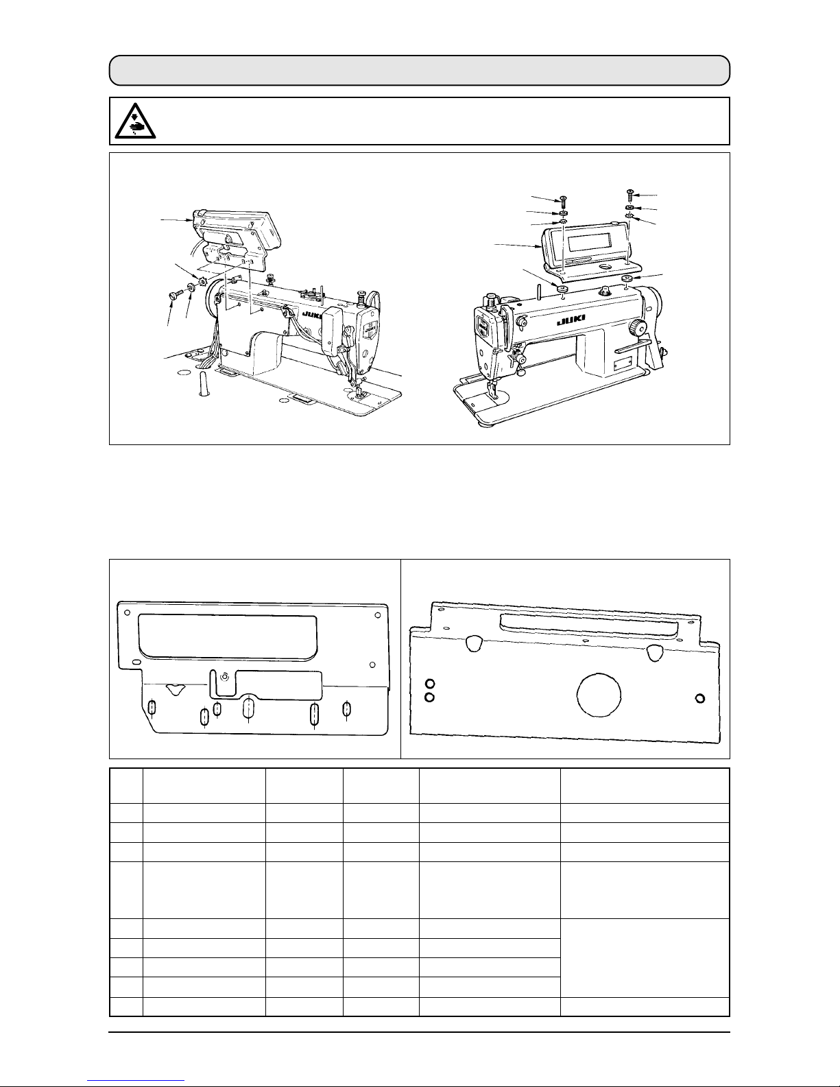
1. INSTALLINGTHE OPERATION PANEL ................................................................... 1
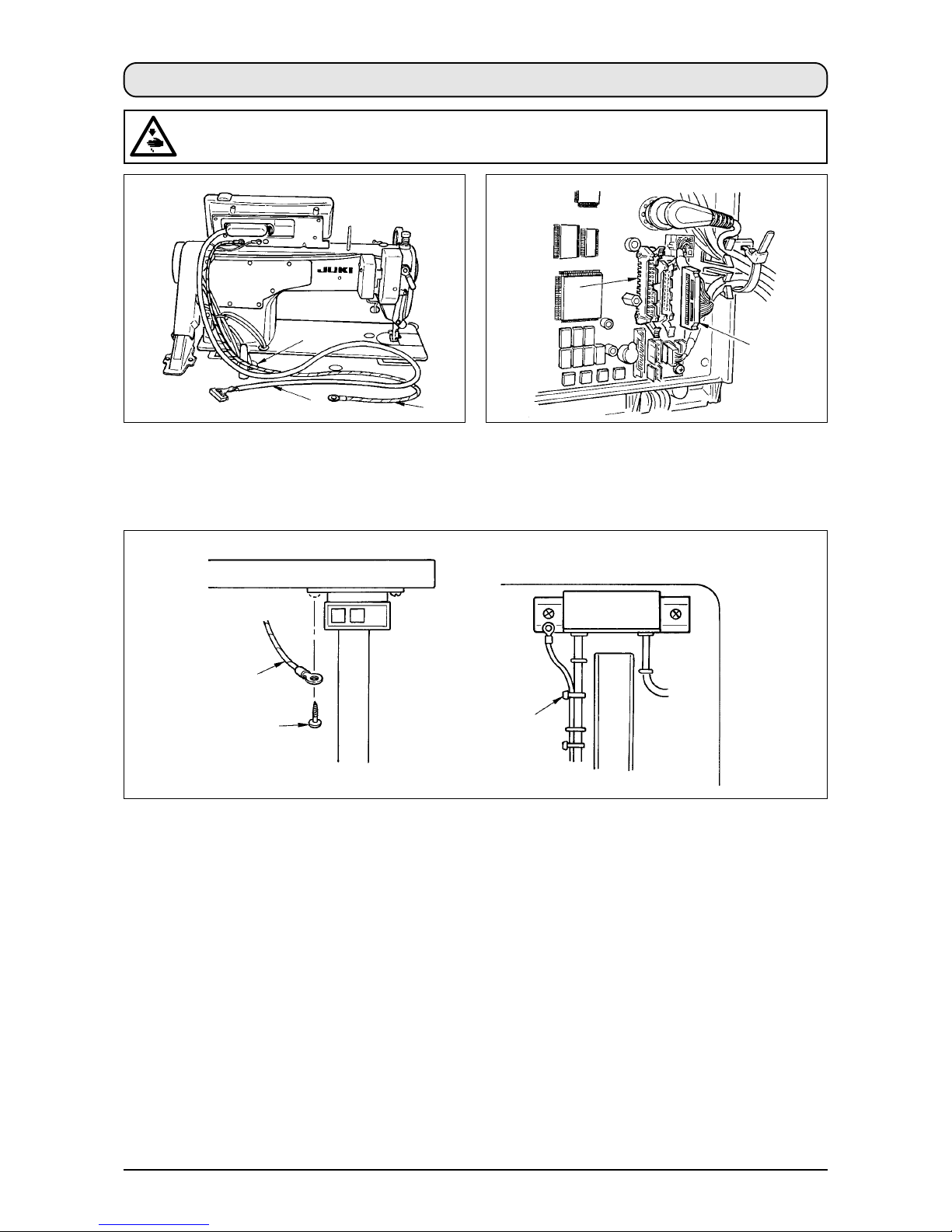
2. CONNECTINGTHE CORD........................................................................................2
3. HOWTO USETHE OPERATION PANEL .................................................................. 3
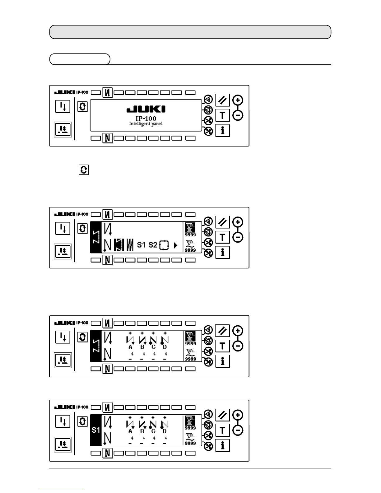
3-1. Names and functions of each components ........................................................................ 3
3-2. Adjusting the contrast of the operation panel display ...................................................... 5
3-3. Production control switch connecting connector.............................................................. 5
4. STANDARD PANEL...................................................................................................6
4-1. Screen list .............................................................................................................................. 6
4-2. How to operate the operation panel for sewing stitching patterns .................................. 8
(1) Reverse stitching pattern...................................................................................................................8
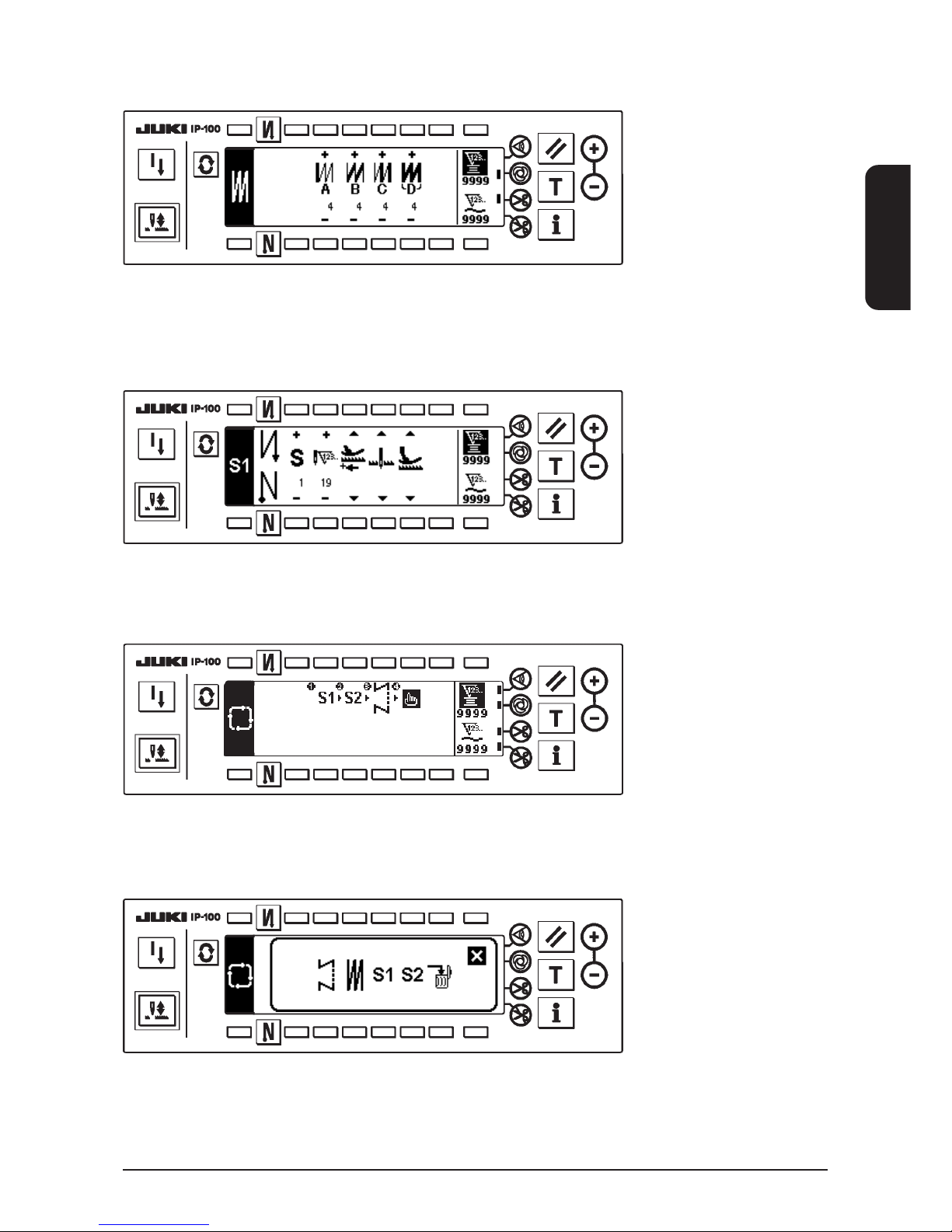
(2) Overlapped stitching pattern...........................................................................................................10
(3) Programmed stitching pattern ........................................................................................................11
(4) Cycle sewing pattern........................................................................................................................15
4-3. How to use the bobbin thread counter.............................................................................. 17
4-4. No. of pcs. counter .............................................................................................................. 18
4-5. Re-sewing switch ................................................................................................................ 18
4-6. Needle up/down compensation switch ............................................................................. 19
4-7. ON/OFF switch of the material edge sensor ............................................................... 19
4-8. Automatic thread trimming switch .............................................................................. 19
4-9. One-shot automatic stitching switch ........................................................................... 19
4-10.Thread trimming prohibition switch ........................................................................... 19
4-11. Key lock.............................................................................................................................. 19
4-12. Information......................................................................................................................... 20
(1) Sewing management information ...................................................................................................20
(2) Production control function ............................................................................................................24
(3) Working measurement function ......................................................................................................26
4-13. Setting for functions ......................................................................................................... 28
(1) How to change over to the function setting mode ........................................................................28
(2) Function setting list .........................................................................................................................31
5. PANEL FOR LH-4168/4188..................................................................................... 34
5-1. Screen list ............................................................................................................................ 34
5-2. How to operate the operation panel for sewing stitching patterns ................................ 38
(1) Reverse stitching pattern.................................................................................................................38
(2) Overlapped stitching pattern...........................................................................................................40
(3) Corner pattern...................................................................................................................................41
(4) Step pattern.......................................................................................................................................47
(5) Cycle sewing pattern........................................................................................................................50
5-3. How to use the bobbin thread counter.............................................................................. 51
5-4. No. of pcs. counter .............................................................................................................. 52
5-5. Re-sewing switch ................................................................................................................ 53
5-6. Needle up/down compensation switch ............................................................................. 54
5-7. ON/OFF switch of the material edge sensor ............................................................... 54