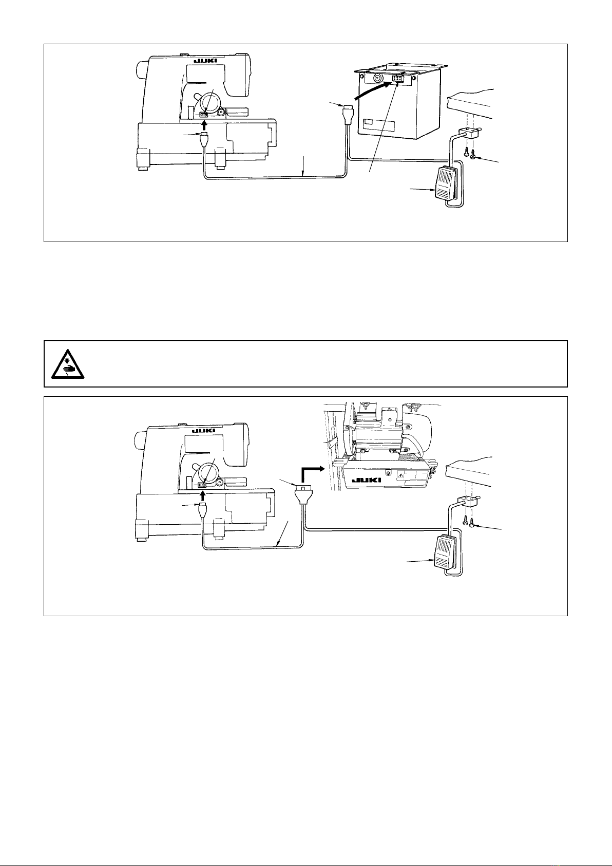
JUKI TC16 User manual

ENGLISH
TC16
INSTRUCTION MANUAL

i
CAUTION
This Instruction Manual is intended for the TC16. To use this product when it is installed on a
machine (sewing machine), make sure to read and fully understand the “IMPORTANT SAFETY
INSTRUCTIONS” provided in the Instruction Manual for the machine on which this product is to
be installed in advance.
For a clearer view of the TC16 illustrations of the machine (sewing machine) are simplied, and
illustrations of some of the safety devices are partially omitted.
Read safety instructions carefully and understand them before using.
Retain this Instruction Manual for future reference.

ii
CONTENTS
SPECIFICATIONS ................................................................................................................. 1
INSTALLATION OF THE DEVICE ........................................................................................ 2
1. Components of device (components packed together with a single unit of device at the time of
delivery).................................................................................................................................................2
(1) TC16A Type with control box (220 to 440V) ..........................................................................................2
(2) TC16B Type with control box (100 to 240V) ..........................................................................................2
(3) TC16C Type for servo-motor ..................................................................................................................2
2. Installing the control box (for TC16A and TC16B only) .................................................................... 3
3. Replacing procedure of the cloth plate (left) when installing TC16 after setting up the sewing
machine.................................................................................................................................................3
4. Installing the tape guide (auxiliary presser)....................................................................................... 3
5. Installing the tape cutter unit............................................................................................................... 4
6. Connecting the cord.............................................................................................................................4
(1) TC16A,TC16B (with control box) types.................................................................................................4
(2) Setting the supply voltage......................................................................................................................4
(3) TC16C (for servo-motor) type ................................................................................................................5
7. Installation and setting SC-921 (for TC16C only) .............................................................................. 6
(1) Installing procedure................................................................................................................................6
(2) Change of the setting .............................................................................................................................8
OPERATION........................................................................................................................ 10
ADJUSTMENT OF COMPONENTS.....................................................................................11
1. Replacing the moving knife or the counter knife ............................................................................ 11
2. Adjusting the angle of the counter knife .......................................................................................... 12
3. Adjusting the lift height of the moving knife.................................................................................... 12
TEST CUT ........................................................................................................................... 13

– 1 –
Applicable model : MF-7500(D)-C11, MF-7500(D)-E11/MD11
Tape width used : Max. 40 mm (nished width)
Applicable motor Name of device Type
Clutch motor TC16A With control box (220 to 440V)
TC16B With control box (100 to 240V)
SC-921 TC16C For servo-motor
SPECIFICATIONS

– 2 –
(3) TC16C Type for servo-motor
1. Components of device (components packed together with a single unit of device at the
time of delivery)
(1) TC16A Type with control box (220 to 440V)
(2) TC16B Type with control box (100 to 240V)
① ② ③ ④
Part No. 40043920 SM6051402TP 40019893 40042221
Description Tape cutter unit Tape cutter unit setscrew Tape guide Knee switch B (asm.)
Q'ty 1 2 1 1
Q'ty 2 2 2 1
① ② ③ ④
Part No. 40043920 SM6051402TP 40019893 40049440
Description Tape cutter unit Tape cutter unit setscrew Tape guide Knee switch C (asm.)
Q'ty 1 2 1 1
⑤ ⑥ ⑦
Part No. D2113555B00 SK3514000SC EA9500B0100
Description Cord clamp ttings Knee switch wood screw Clip band
Q'ty 2 2 2
INSTALLATION OF THE DEVICE
⑤ ⑥ ⑦
Part No. D2113555B00 SK3514000SC EA9500B0100 40039579 (TC16A)
40039580 (TC16B)
Description Cord clamp ttings Knee switch wood screw Clip band Control box
⑧

– 3 –
Install the control box on the bottom surface of the table with
wood screws supplied as accessories with the unit.
2.
Installing the control box (for TC16A and TC16B only)
Drawer
Stand
Control Box
WARNING :
To protect against possible personal injury due to abrupt start of the machine, be sure to start the following work
after turning the power off and ascertaining that the motor is at rest.
3.
Replacing procedure of the cloth plate (left) when installing TC16 after setting up the sewing machine
WARNING :
To protect against possible personal injury due to abrupt start of the machine, be sure to start the following work
after turning the power off and ascertaining that the motor is at rest.
1) Loosen four setscrews and remove the standard
cloth plate (left) .
2)
Install cloth plate (left) for tape cutter
with three set-
screws
.
Part No. Description
For C11 40019896 TC cover
For E11 70003999 TC cover for subclass
Moreover, use the setscrews of the standard cloth
plate (left) for installing.
4. Installing the tape guide (auxiliary presser)
WARNING :
To protect against possible personal injury due to abrupt start of the machine, be sure to start the following work
after turning the power off and ascertaining that the motor is at rest.
1) Remove presser foot from the sewing machine.
2) Remove presser spring setscrew and tighten tape
guide together with the presser spring.
(Install tape guide so that it is placed on presser
spring .)

– 4 –
5. Installing the tape cutter unit
WARNING :
To protect against possible personal injury due to abrupt start of the machine, be sure to start the following work
after turning the power off and ascertaining that the motor is at rest.
1) Install tape cutter unit on cloth plate (right)
using two setscrews (hexagon socket head bolt M5
14 mm long) supplied as accessories.
2) Adjust the whole orientation so that counter knife
of the tape cutter comes in parallel contact with rear
end of the throat plate
Perform the work with care so as not to
allow your hands or the like to touch the
blade section of the cutter.
6. Connecting the cord
Connecting procedures of the cord are classied in two kinds below.
The respective connecting procedures are as shown below.
Classication Name of device Type
(1) TC16A With control box (220V to 440V)
TC16B With control box (100V to 240V)
(2) TC16C For servo-motor
Brown/Sky blue
Motor power cord
Ground wire
Power switch
(1) TC16A,TC16B (with control box) types
WARNING :
Draw out the power plug before starting the work so as to prevent accidents caused by abrupt start of the sewing
machine.
Connect power cords of the control box together with
the motor power cords to the secondary side of the power
switch after conrming the electrical specications of the
rating plate attached to the control box.
(2) Setting the supply voltage
TC16A
For 200 V
TC16B Change round the transformer terminals according to
the supply voltage to be used.

– 5 –
Install knee switch on the bottom surface of the table using wood screws (SK3514000SC) supplied as accessories,
and connect relay cord to control box and cutter unit .
6P connector (relay cord) / control box
3P connector (relay cord) / tape cutter unit
A : 3P connector
B : 6P connector
WARNING :
Draw out the power plug before starting the work so as to prevent accidents caused by abrupt start of the sewing
machine.
(3) TC16C (for servo-motor) type
Install knee switch on the bottom surface of the table using wood screws (SK3514000SC) supplied as accessories,
and connect relay cord to CN36 connector of SC-921 and cutter unit .
14P connector (relay cord) / CN36 connector of SC-921
3P connector (relay cord) / tape cutter unit
A : 3P connector
B : 14P connector
B
A

– 6 –
7. Installation and setting SC-921 (for TC16C only)
For the details of installation of SC-921, refer to the Instruction Manual for SC-921.
(1) Installing procedure
1) Referring to the Instruction Manual supplied with the
SC-921, connect the SC-921 control box to the M51N
motor.
2) Installing procedure of the synchronizer
Attach synchronizer xing bracket on the sewing ma-
chine with two setscrews to install synchronizer .
Secure the cord of the synchronizer on synchronizer
xing bracket with clip band . Fix the cord at the
position as shown in the illustration with cord clamp
and setscrew .
* Refer to the Instruction Manual for the MF-7500 for how
to attach the belt cover.
3) Installing procedure of the exclusive cord for MF
Connect the exclusive cords for MF to the respective
designated connectors as follows.
◦ Synchronizer cord / CN33
◦TC cord /CN36

– 7 –
4) Adjusting the synchronizer
1. Loosen screw and remove cover .
2. Turn disk on this side by hand, and adjust the adjusting
mark "B" of disk in the rear to edge of disk .
3. Temporarily tighten the synchronizer to the lower main
shaft handwheel with screw .
4. When the power is turned ON, the sewing machine turns
approximately by one half and stops.
5. Turn OFF the power, and loosen screw .
6. Holding section of the synchronizer so as not to move,
turn the upper main shaft handwheel, adjust mark of the
handwheel to the position where mark on the machine
head side aligns with it, and temporarily tighten screw .
7. Again, turn ON the power, and conrm that the sewing ma-
chine stops at the position where mark of the handwheel
aligns with mark on the machine head side. Then tighten
screw .
8. After the adjustment, be sure to attach cover and tighten
screw .
9. After the adjustment above has been performed, when the
sewing machine stops at the DOWN position, top end of
the looper is located at the position where it has scooped
loop of left needle thread as shown in the gure 1.
When using the synchronizer as UP/DOWN
stop position type without using the thread
trimmer device, change the setting of
the function setting No. 74 to "1 (thread
trimming) / 0 (UP/DOWN position)". Thread
trimmer safety device error occurs unless
the setting is changed, and it is impossible
to operate the sewing machine. So, be
careful.
Fig. 1
WARNING :
To protect against possible injury to hands or
ngers due to abrupt start of the machine during
performing adjustment, perform the adjustment of
the stop position under the function setting mode.

– 8 –
(2) Change of the setting
[Adjusting procedure]
1) Turn the power OFF.
2) Pressing switch , turn ON the power.
3) The screen display is as shown in the
gure. (In the case the screen display
does not change, re-carry out the steps of
procedure 1) and 2).)
Caution: If you have already set another
number and data, the last number
and the data you have set are dis-
played.
4) Press switch or to activate the dis-
play (No. 95) shown in the gure.

– 9 –
5) Change type of the machine head by
pressing switch (or switch ).
Then select dL87 →MFS1 or MF.
Machine head Display of
option
Factory-set
sewing speed
sti/min
Maximum sewing
speed sti/min
MF-7500D-C11
MFS1 4000 5000MF-7500D-E11
MF-7500(D)-E11/MD11
MF-7500-C11 MF 4500 6500
6) After selecting the type of machine head,
by pressing switch ( switch
), the step proceeds to 96 or 94, and
the display automatically changes to the
contents of the setting corresponding with
the type of machine head.
Turn the power OFF.
When you have changed the
machine head type, the previous
settings are restored to the stan-
dard ones.
Be aware that the setting changes you have made will not take effect if you turn the power OFF with-
out carrying out the conrmation operation.

– 10 –
OPERATION
WARNING :
Do not place hands, ngers, etc. within the operating range of the tape cutter when the power is turned ON so as
to prevent accidents caused by abrupt start of the sewing machine.
In addition, do not use the tape cutter unit with safety cover and the like removed.
Press knee switch when cutting the tape at the start or
the end of sewing. The moving knife of the cutter comes
down and the tape is instantly cut. (Cut width is possible
up to 40 mm.)
Besides, when performing sewing without using tape
cutter , turn OFF (press to the lower side) cutter motion
switch located on the right side of tape cutter unit ,
and tape cutter does not operate even when the knee
switch is pressed. This action can prevent tape cutter
from being carelessly operated by the wrong operation.
For safety sake, turn OFF cutter motion
switch when tape cutter is not used.

– 11 –
ADJUSTMENT OF COMPONENTS
Standard adjustment of assembling adjustment of the tape cutter mechanism components has been performed at the
time of delivery. However, when performing assembling due to the replacement of components or the like, perform the
adjustment with the dimension value below.
Perform the adjustment work by the maintenance engineers who are familiar with the sewing machine
and trained for the safety so as to prevent accidents caused by unfamiliarity or wrong adjustment.
1. Replacing the moving knife or the counter knife
WARNING :
Do not place hands, ngers, etc. within the operating range of the tape cutter when the power is turned ON so as
to prevent accidents caused by abrupt start of the sewing machine.
In addition, do not use the tape cutter unit with safety cover and the like removed.
When the moving knife or the counter knife is worn out and replacement is necessary, perform the replacement by the procedure
below.
1) Remove the whole of tape cutter unit from the sew-
ing machine.
2) Loosen four setscrews and remove the whole of
safety cover .
3) Loosen two setscrews and replace counter knife
.
4) Loosen two setscrews and replace moving knife
.
7.5mm
5) Install safety cover in its home position.
In addition, adjust the dimension of the height of the
cover as shown in the illustration on the left side.

– 12 –
2. Adjusting the angle of the counter knife
A
To improve the sharpness of the cutter, it is necessary for
the moving knife to engage with the counter knife slightly
slantwise.
It is the standard that there is a clearance of less than
0.1 mm at the root of plane of engagement
1) Slightly loosen two setscrews in the counter knife
(temporarily tightened state) and turn adjustment
screw for adjustment.
2)
When turning adjustment screw counterclockwise,
the angle of counter knife in terms of the moving
knife is increased and the knives are set to the state
that they engage with each other more slantwise.
Large
Small
WARNING :
Do not place hands, ngers, etc. within the operating range of the tape cutter when the power is turned ON so as
to prevent accidents caused by abrupt start of the sewing machine.
In addition, do not use the tape cutter unit with safety cover and the like removed.
When the angle to engage with each other
slantwise is large, the initial sharpness is
improved. However, on the contrary, the
blade section is quickly worn out, and the
knives are put in the state of poor lasting
quality.
Accordingly, make the angle of engage-
ment as small as possible within the range
where the tape can be cut.
A : Less than 0.1 mm
3. Adjusting the lift height of the moving knife
The lift height of the moving knife has been factory-adjusted at the time of delivery. However, when performing the re-
placement of the rotary solenoid or the like, perform re-adjustment by the procedure below.
WARNING :
Do not place hands, ngers, etc. within the operating range of the tape cutter when the power is turned ON so as
to prevent accidents caused by abrupt start of the sewing machine.
In addition, do not use the tape cutter unit with safety cover and the like removed.
1) Remove the safety cover.
(For the replacing procedure of the safety cover,
refer to ". ADJUSTMENT OF COMPONENTS"
p.11.)
2) Loosen solenoid lever clamp screw .
3) Loosen lock nut of stopper bolt .
4) Turn stopper bolt , and adjust the height of the
moving knife to 26 mm from the counter knife.
5) Fix lock nut of the stopper bolt.
6) Adjust the longitudinal position so that the clearance
between solenoid lever and TC lever is 4.1
mm and x the position with clamp screw .
Interference of components occurs and the
cutter fails to properly work when it works
unless the clearance between solenoid le-
ver and TC lever is correctly adjusted.
7) Install the safety cover in its home position.
26mm
4.1mm

– 13 –
TEST CUT
Perform the test cut of the tape cutter by the procedure below using the material for testing before entering sewing of the
products.
WARNING :
Do not place hands, ngers, etc. within the operating range of the tape cutter when the power is turned ON so as
to prevent accidents caused by abrupt start of the sewing machine.
In addition, do not use the tape cutter unit with safety cover and the like removed.
1) Sew tape on the material for testing.
2) Press the knee switch to actuate tape cutter and
check that the tape is smoothly cut.
3) When the condition of cutting is not good, it is nec-
essary to adjust the pressing pressure of the cutter.
Loosen lock nut of adjustment screw and
perform the adjustment of the pressing pressure.
* Pressing pressure of the cutter is increased
when adjustment screw is screwed up.
Initial sharpness is improved when the
pressing pressure of the cutter is high.
However, on the contrary, the blade section
is quickly worn out, and the cutter is put in
the state of poor lasting quality. According-
ly, make the pressing pressure as low as
possible within the range where the tape
can be cut.
* Standard adjustment value is the pressing pres-
sure of 30 N when measuring with the spring
balancer.
In addition, when the condition of cutting is not good even
when adjusting the pressing pressure of the cutter, perform
the adjustment of the angle of counter knife.
(Refer to ". ADJUSTMENT OF COMPONENTS" p.11.)
Table of contents
Other JUKI Sewing Machine manuals

JUKI
JUKI DDL-9000BHS User manual

JUKI
JUKI LBH-1702 User manual

JUKI
JUKI DLM-5400NDD-7 User manual

JUKI
JUKI DSC-245 User manual

JUKI
JUKI DDL-5550N User manual

JUKI
JUKI DDL-9000A User manual

JUKI
JUKI MF-7800/UT25 User manual

JUKI
JUKI LU-1510N Quick start guide

JUKI
JUKI LZ-271 User manual

JUKI
JUKI LU-2810-7 Series User manual

JUKI
JUKI LU2-4652-B1T User manual

JUKI
JUKI MB-1373 User manual

JUKI
JUKI DDL-8700A-7 User manual

JUKI
JUKI LZ-2290CS User manual

JUKI
JUKI DU-1481 Series User manual

JUKI
JUKI HZL-80 series User manual

JUKI
JUKI DLN-9010A User manual

JUKI
JUKI LK-1900A-SS User manual

JUKI
JUKI MO-2000QVP User manual

JUKI
JUKI MEB-3810N Series User manual