JUKI HZL-G Series User manual

SERVICE Manual
HZl-G Series
COMPuTER SEWInG MaCHInE

– 14 –
1.0 ± 0.1 mm
1.0 ± 0.1 mm
6-2 Adjusting the needle entry point
○Remove the face cover.
Adjustment procedure
1. Select the straight stitch using the pattern selecting button. Choose center needle position.
2. Assemble a needle #14 into the needle bar, loosen the setscrew in the eccentric collar and adjust the feed
bar eccentric collar so that the needle meets the center of the needle slot in the throat plate when it
reaches the top face of the throat plate by turning the hand wheel.
6-3 Feed dog height
○Do not remove the throat plate.
Adjustment procedure
1. Set the amount of feed to 0 (zero).
2. Turn the hand wheel to bring the feed dog to its highest dead point.
3. Using a tapered-head slotted screwdriver, turn shaft a on the left side and shaft b on the right side.
4. Adjust the feed dog height so that the front and rear ends of the feed dog are spaced 1.0±0.1 mm from
the throat plate surface. Adjust the rear end height of the feed dog with shaft a, and front end height with
shaft b.
Setscrew
Feed bar eccentric collar
Shaft a Shaft b
Shaft a
Shaft b

COnTEnTS
[1]SpecicationsofHZL-GSeries............................................................1
[2]Searchbytrouble(relatedtomechanicalcomponents).....................3
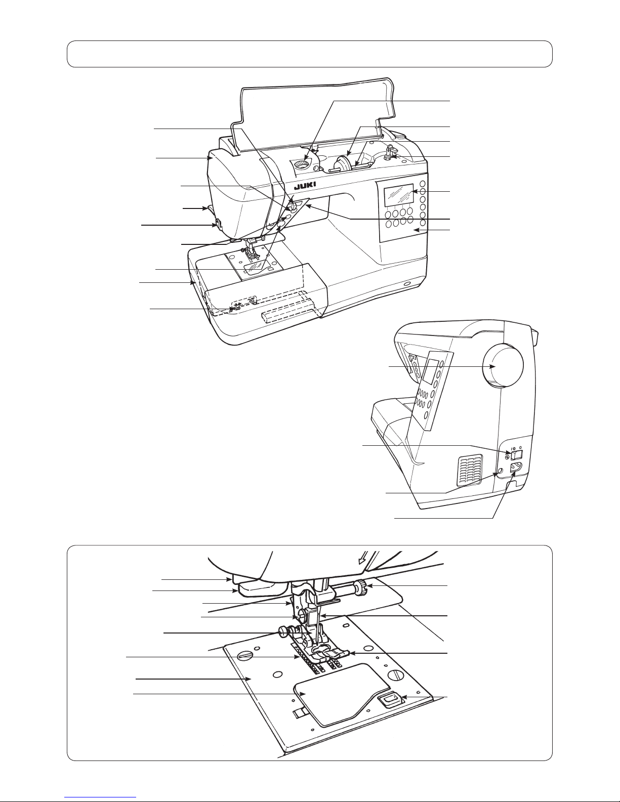
[3]Principalparts........................................................................................4
[4]Disassemblingthemachinecovers.....................................................5
[5]PCBconnectiondiagram......................................................................9
[6]Adjustment...........................................................................................13
6-1 Adjustingtheneedlebarheight......................................................................13
6-2 Adjustingtheneedleentrypoint.....................................................................14
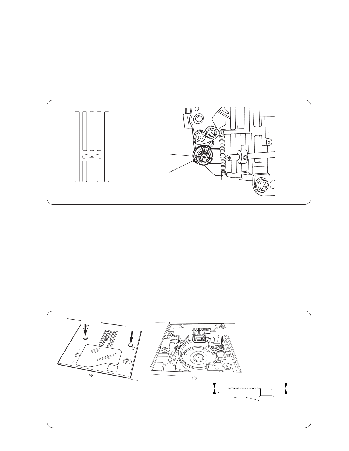
6-3Feeddogheight...............................................................................................14
6-4Timingbelt........................................................................................................15
6-5Feedtiming.......................................................................................................15
6-6 Timingbetweentheneedleandthehook.......................................................16
6-7 Clearancebetweentheneedleandthebladepointofhook.........................17
6-8 Positionofthehookrotationstopperplate....................................................18
6-9Adjustingthebobbinthreadtension..............................................................18
6-10 Adjustingthediskopeningamount..............................................................19
6-10-1Adjustingthetensionreleaseadjustingplate...................................19
6-10-2 Tensiondiskopeningamount............................................................19
6-10-3Basetensionopeningamount............................................................20
6-10-4Adjustingthediskopeningamountatthetimeofthreadtrimming
(HZL-G210)...............................................................................................21
6-11 Adjustingtheneedlethreadtension.............................................................21
6-12 Verticalpositionoftheneedlethreadinghook............................................22
6-13Adjustingthepresserfootliftingswitch......................................................23
6-14Adjustingthepresserbarheight..................................................................23
6-15Motorbelt........................................................................................................24
6-16 Automaticthreadtrimming(HZL-G210).......................................................25
6-16-1Lateralpositionofthethreadtrimmingmechanismbase..........................25
6-16-2Phaseofthecatchingunitdrivingcam.......................................................26
6-16-3Replacingthethreadtrimmingblade..........................................................27
6-17 Longitudinalfeed...........................................................................................28
6-18Buttonhole......................................................................................................29
6-19Servicemode.................................................................................................30
6-20-1 Servicemodescreen...................................................................................30
5-20-2Service-modeitemsanddescriptions.........................................................30
Be sure to observe the following to protect against a re, electrical shock, injury or damaged
components.
* Be sure to unplug the machine before disassembly, assembly or adjustment of the machine.
* Be sure to carefully prevent electric cords from being caught, coated surfaces from being
damaged as well as wrong wiring during assembly.
* Be sure to use the proper genuine parts when changing any of the machine parts.
CauTIOn:

– 1 –
(1) Power switch
・220-240V AC common to 50/60 Hz
・120V AC common to 60 Hz
(2) Power consumption
・65 W
(3) Dimensions and weight
・Dimensions Main unit: 445 (width) x 210 (depth) x 290.5 (height) (mm)
Case set: 510 (width) x 257 (depth) x 305 (height) (mm)
・Weight Main unit: G210 9.4 kg G110 8.9 kg
(4) Revolution control
・Slide style speed control
Straight stitch 80 〜900 sti/min (SPM)
Pattern stitch 80 〜750 sti/min (SPM)
Reverse stitch 80 〜110 sti/min (SPM)
80 〜900 sti/min (SPM) (when the speed controller is used)
Bobbin winding 1500 〜3000 sti/min (RPM)
Low-speed start 80 〜110 sti/min (SPM) (approx. 1 second only when the power switch is turned ON)
・Foot controller
Even when the foot controller is used, the speed control function by means of the slider is effective.
To stop the machine, either release the foot controller or press start/stop button.
The number of revolutions is controlled in the way same with the case of the slide speed control.
Thread trimming switch (Press heel side of foot controller.)
・Safety control
When the motor shaft of the sewing machine is accidentally constrained, the power supply to the
motor is stopped within two seconds.
When the motor is overheated, the built in thermal switch stops the power to the motor.
Note that the machine can be restarted once the motor spontaneously cools down.
(5) Stop position
・ Upon nishing sewing, the machine stops according to the preset needle stop position (with its needle up or
down).
・ Upon nishing reverse stitching, the machine stops with its needle down.
・In the case the machine is started with the presser foot lifting lever raised, the machine stops with its needle
up.
・Needle moves down when the machine has preset so that the needle stops at its up position and needle up/
down button is pressed.
・Needle moves up when the machine has preset so that the needle stops at its down position and needle up/
down button is pressed.
・In the case of fault, the machine stops immediately (stop position varies).
(6) Zigzag width
・Max. 7 mm depending on the pattern selected
[1] Specications of HZL-G Series

– 2 –
(7) Amount of feed
・The amount of feed is changed in increments of 0.2 mm by the stitch length adjusting dial.
(For the parallel parts of a buttonhole and satin stitches, the amount feed is changed in
increments of 0.1 mm.)
Default setting: 2.4 mm (for straight stitching)
(8) Pattern selection
・Selection of three different kinds of patterns; Selection of number shifts
・Segment type LCD
(9) Number of patterns
・180
(10) Automatic threading device
・The hook section makes a turn by lowering the threading lever, and automatically returns to its original
position after completion of threading.
(11) Automatic lock stitch
When the backtacking switch is turned ON:
・Straight stitch: Three stitches are sewn in normal direction and three stitches are sewn in reverse
direction at the beginning and end (the reverse switch is turned ON) of sewing.
Amount of feed: Same with the preset amount of feed
・Other patterns: Zero-feed is inserted and one each stitch is sewn in the normal and reverse directions
at the beginning and end (the reverse switch is turned ON) of sewing.
Amount of feed: Fixed at 0.6 mm
(12) Buttonholing
Auto-return type full automatic buttonholing
Buttonholing size detection

– 3 –
[2] Search by trouble (related to mechanical components)
Phenomenon Item to be checked
Faulty thread tension 6-8: Position of the hook rotation stopper plate
6-9: Adjusting the bobbin thread tension
6-10-2: Tension disk opening amount
6-10-3: Base tension opening amount
6-11: Adjusting the needle thread tension
Stitch skipping 6-1: Adjusting the needle bar height
6-2: Adjusting the needle entry point
6-5: Feed timing
6-6: Timing between the needle and the hook
6-7: Clearance between the needle and the blade point of hook
Thread breakage 6-1: Adjusting the needle bar height
6-6: Timing between the needle and the hook
6-8: Position of the hook rotation stopper plate
Hitch stitch 6-2: Adjusting the needle entry point
Faulty material feed 6-3: Feed dog height
6-14: Adjusting the presser bar height
Contact between needle and
throat plate or hook.
6-2: Adjusting the needle entry point
6-5: Feed timing
6-6: Timing between the needle and the hook
Faulty pattern shape 6-3: Feed dog height
6-17: Longitudinal feed
Faulty automatic thread trimming 6-10-4: Adjusting the disk opening amount at the time of thread trimming
6-16-1: Lateral position of the thread trimming mechanism base
6-16-2: Phase of the catching unit driving cam
6-16-3: Replacing the thread trimming blade
Faulty operating noise 6-4: Timing belt
6-15: Motor belt
Fault buttonholing 6-18: Buttonhole
Needle threader 6-12: Vertical position of the needle threading hook
Fails to start sewing 6-13: Adjusting the presser foot lifting switch

– 4 –
[3] Principal parts
Hand wheel (pulley)
Power switch
Machine-socket-inlet
Foot-controller-jack
Spool cap (large)
Spool pin
LCD Screen
Operational buttons
Face plate cover
Start/stop button
Auxiliary bed
(accessory case)
Presser foot lifting lever
Drop feed knob
Needle setscrew
Needle
Presser foot
Presser foot releasing button
Feed dog
Throat plate
Hook cover
Bobbin winding shaft
Hook cover release
button
Presser foot holder setscrew
Thread trimming button
Thread cutter Reverse stitch button
Speed controller
Needle up/down button
Thread tension
adjustment dial
Buttonholing lever
Threading lever
Presser foot holder

– 5 –
○To remove the top cover, bow the hinge section of the right side of the cover.
○Remove setscrews 1from the cover. Then, remove the cover.
○Remove setscrews 2and 3from the throat plate.
Then remove the throat plate.
[4] Disassembling the machine covers
1) Top cover
2) Face cover
3) Throat plate
1
23

– 6 –
○Remove setscrew 4from the thread tension cover.
Remove the thread tension cover.
○Remove setscrews 5to 8from the spool cover.
○Pull out the cable of bobbin winder motor from the microcomputer PCB.
Loosen the setscrew of the grounding wire. Remove the grounding wire.
○Remove the spool cover from the main unit of the machine, paying attention
to the base tension.
○Remove setscrews 9and !0 from the bottom cover of the free arm.
Remove the bottom cover.
4) Spool cover
5) Bottom cover of the free
arm
Microcomputer PCB
Setscrew
of the
grounding
wire
Base tension
5
6
7
8
4
9
!0

– 7 –
6) Bed cover
7) Upper cover of the free
arm
8) Face plate cover
○Remove setscrews !1 to !3 from the rubber cushion of the bed cover.
Remove setscrew !4 from the bed cover. Remove setscrews !5 and !6 from
the metal plate. Remove the bed cover.
○Remove setscrew !7 from the upper cover of the free arm.
Remove the cover.
○Remove setscrews !8 and !9 from the face plate cover.
Remove the face plate cover.
!7
!1
!2
!3
!4
!5 !6
!8
!9

– 8 –
9) Front panel ○Remove setscrews @0 and @1 from the front panel.
○Put a thin screwdriver in the notch in the rising section under the arm and pry
off the front panel and hook Aof the rear panel.
○Opening the right side of the front panel in the direction of the arrow, tap Z
section with your hand to remove hook Blocated at the bed surface.
○Lastly, remove hook Clocated at the lower side of the machine jaw.
○Remove connectors for SUMI-card, start switch and LED lamp from the
microcomputer PCB when necessary.
10) Rear panel ○Remove setscrews @2, @3 and @4 from the rear panel.
Remove the rear panel with the presser foot lifting lever raised.
@1
@0
A
B
C
Z
@2
@3
@4
Open
Notch

– 9 –
[5] PCB connection diagram
・Microcomputer PCB
CN10
Connector
No. Destination Terminal
No.
CN1 ON_HAND_LED_CIRCUIT_BOARD_2 (Not installed) 1 5V
CN2 BOBBIN_WINDING_MOTOR 1 Bobbin winder switch
2 GND
3 Bobbin winder motor (+) (29V)
4 Bobbin winder motor (-)
CN3 OST SW 1 Presser foot lifting switch
2 GND
CN4 BH_SW 1 GND
2 BHR SW
3 BHS SW
4 5V
CN5 MAIN_SHAFT_DETECTION_CIRCUIT_BOARD 1 5V
2 Motor pulse
3 S1
4 S2
5 S3
6 GND
CN6 FLASH MEMORY INTERFACE 1 5V
6 GND
CN7 FOR FACTORY 2 GND
4 GND
CN8 RESERVE (Not installed) 1 5V
3 GND
CN9 CONTROLLER_SOCKET 1 GND
2 CONTROLLER

– 10 –
Connector
No. Destination Terminal
No.
CN10 POWER_SUPPLY_RELAY_LEAD_WIRE 1 30V
2 30V
3 NC
4 GND
5 GND
CN11 MAIN MOTOR 1 MAIN MOTOR (+) (29V)
2 MAIN MOTOR (-)
CN12 THREAD_TRIMMING_STM 1 A
2 A
3 B
4 B
CN13 FEED_STM 1 A
2 A
3 B
4 B
CN14 NEEDLE_THROW_STM 1 A
2 A
3 B
4 B
CN15 THREAD_TRIMMING_STM_ORIGINAL
_POINT_CIRCUIT_BOARD
1
2 Detection signal
3 GND
CN16 SW/SLIDE_VOLUME_CIRCUIT_BOARD 1 LED G
2 LED R
3Thread trimming/needle
up/down switch
4 Reverse stitch switch
5 S/S switch
6
7 5V
8Speed control variable
resistor
9 GND
CN17 UNDER_ARM_LED_CIRCUIT_BOARD
(Not installed)
CN18 ON_HAND_LED_CIRCUIT_BOARD_1 1 5V
2
CN19 PANEL_CIRCUIT_BOARD 1 - 3 NC
4 - 7 Switch strobe
8, 9 5V
10, 11 GND
12 LCD signal
13, 14 3.3V PU
15, 16 LCD signal
17 3.3V
18 GND
19 - 22 NC
23 - 26 Switch data
27 - 29 NC
30 GND
8.5Ω
4.0Ω
5.0Ω
8.5Ω
4.0Ω
5.0Ω

– 11 –
・Display PCB
・Power PCB
Connector No. Destination Check
CN1 POWER SW AC input
CN2 POWER_SUPPLY_RELAY_LEAD_WIRE 1-2PIN 29V, 4-5PIN GND(FG)
To be connected to CN19
of microcomputer PCB
CN2
CN1

– 12 –
・Connection block diagram

– 13 –
[6] Adjustment
6-1 Adjusting the needle bar height
○Remove the face cover.
Adjustment value:
・Distance from the bottom end of the pin inside needle bar surface to the top surface of the throat plate:
19 mm
・When the needle is mounted, the needle eye tilts rightward by 2 degrees.
Adjustment procedure 1.
1. Select the straight stitch using the pattern selecting button. Choose center needle position.
2. Make a gauge needle by cutting a household needle HA x 1 to dimension A. Fit the gauge needle into the
needle bar.
3. Prepare an appropriate metal plate of thickness B. (A = 19 mm - B)
4. Bring the needle bar to its lowest dead point. Slightly loosen needle bar connecting stud setscrew 1as
long as the needle does not slip off from the connecting stud.
5. Place the metal plate on the throat plate. Move the needle bar up and down by hand to adjust so that the
cut surface of the gauge needle aligns with the top surface of the metal plate. Then, turn the needle bar
by two degrees of an angle as illustrated in the sketch below.
6. Temporarily tighten needle bar connecting stud setscrew 1 and reconrm that the needle bar is correctly
adjusted. Then, securely tighten the setscrew.
Adjustment procedure 2.
1. Assemble a household HA x 1 needle #14 into the needle bar, bring the needle bar to its highest dead
point. Move the needle bar in the same way as described in procedure 1 to adjust the needle bar height
so that the needle tip is spaced 15.5 mm from the top face of the throat plate.
19 mm
Metal plate
Throat plate
2°
[Lowest dead point]
A
B
Gauge needle
15.5 mm
[Highest dead point]
HA×1 #14
1

– 15 –
6-4 Timing belt
○Remove the front panel and the microcomputer PCB.
Adjustment procedure
1. Loosen the setscrew in the idler mounting base and loosen the timing belt.
2. Turn the hand wheel to bring the needle bar to its lowest dead point.
3. Turn the hook driving shaft to bring the feed dog to its lowest dead point.
4. Carefully keeping the condition described in steps 2 and 3, set the timing belt on the hook driving shaft
pulley (by temporarily tightening the setscrew in the idler mounting base) so that the setscrew No. 2 in the
pulley is brought to just underside of the pulley.
5. Applying 1.96±0.29 N force to the idler by means of a spring scale, securely tighten the setscrew.
Push the middle part of the screw
with the spring scale.
Setscrew of the idler mounting base
The setscrew No. 2 is located just underside of the hook driving shaft pulley.
6-5 Feed timing
○After checking the feed dog height and the needle bar height, carry out adjustment of the feed timing.
Adjustment procedure
1. Assemble a HA x 1 needle #14 into the needle bar.
2. Loosen setscrew No. 2 in the hook driving shaft pulley.
3. Loosen setscrew No. 1 in the hook driving shaft pulley. Adjust the pulley so that the lower end of the
needle eye in the descending needle #14 is aligned with the top surface of the throat plate when the top
face of the descending feed dog is aligned with the top surface of the throat plate by turning the
hand wheel toward you. After adjustment, tighten the setscrew No. 2.
4. Turn the main shaft by one revolution to conrm the timing.
The lower end of the needle eye in needle
#14 aligns with or is 1 mm or less above
the top surface of the throat plate.
Top surface of the feed dog aligns
with the top surface of the throat plate.
Setscrew No. 2
Setscrew No. 1
1.96 ± 0.29 N

– 16 –
6-6 Timing between the needle and the hook
○Remove the throat plate, the bed cover and the bottom cover of the free arm.
Method for checking
1. Check to be sure that the needle entry point and needle bar height are correct.
2. Select the straight stitch. Select the right needle position by using the zigzag width adjusting dial.
(The needle entry point is shifted to the rightmost side.)
3. Now, turn the hand wheel by hand to bring the needle bar to its lowest dead point.
4. Turn the hand wheel further to gradually lift the needle bar until point C where the needle center is aligned
with the tip of blade point of the hook is reached.
5. At this time, check to be sure that the distance D from the tip of blade point of the hook to the upper end
of the needle eye is 3.1 to 3.3 mm. If this distance is not correctly provided, carry out the following
adjustment.
Adjustment procedure
1. Loosen the setscrew in the hook driving gear which is not visible from underside of the sewing machine
when the needle center aligns with the tip of blade point of the hook.
2. Select the straight stitch and the right needle position. Move the hook driving gear in the rotational
direction to adjust distance D of 3.1 to 3.3 mm is provided between the tip of blade point of the hook and
the upper end of the needle eye when the needle bar is lifted by 1.6 mm from the lowest dead point by
turning the hand wheel by hand.
At this time, the backlash between the hook driving gear and the gear on the hook side may change
depending on the location of the hook driving gear on the hook driving shaft. Adjustment should,
therefore, be carried out with the visible setscrew temporarily tightened, while carefully observing the
hook driving gear in both the rotational direction and axial direction. Adjust the backlash to 0.2 to 0.7 mm
on the periphery of the rotating hook.
3. After conrming the timing between the needle and hook is correctly adjusted, securely tighten both
setscrews.
Caution: After adjustment of the hook, the hook race surface and the bobbin case holder may be stained with
dirt, oil or grease. Wipe them off with alcohol where necessary.
If those parts are left stained, chattering or thread slip-off noise of the bobbin case holder can occur.
Distance D:3.1 to 3.3 mm
1.6 mm
C
Backlash on the periphery of the
rotating hook 0.2 to 0.7 mm
Rotating
hook
Hook
driving
gear
Backlash
Larger
Smaller

– 17 –
6-7 Clearance between the needle and the blade point of hook
○Remove the face cover and the throat plate.
Adjustment procedure
1. Loosen screw 1. Adjust the clearance between the needle and the blade point of the hook to
0.02 to 0.07 mm by turning adjusting shaft 2.
Adjusting the balance of the clearances at the right and left needle entry points
1. Select the zigzag pattern and set the zigzag width to 7 mm. Adjust the balance of the clearances provided
between the needle and the blade point of the hook at the right and left needle entry points.
Left needle position Right needle position Right needle positionLeft needle position
If the clearance is larger at the right needle
entry point, shift 4to the right.
If the clearance is larger at the left needle
entry point, shift 4 to the left.
P section
4
3
Adjustment procedure
1. Select No. 2 of the service mode.
2. Gradually turn adjusting shaft 2 to nd a position where the needle deviates slightly. Now, temporarily
tighten screw 1.
3. Slightly loosen setscrew 3. Adjust the lateral balance of the needle bar by slightly moving right-left
adjuster 4while carefully listening to the noise produced when the needle deviates at the right and left
needle entry points. Then, securely tighten setscrew 3.
4. Additionally turn shaft 2and securely tighten screw 1at the position where the needle does not deviate.
5. Lightly tap P section with ngers. If you hear a needle deviation noise at the right and left needle entry
points, the optimum clearance is provided between the needle and the hook.
1
2
0.02 to 0.07 mm
1
2

– 18 –
6-8 Position of the hook rotation stopper plate
○Remove the throat plate.
Adjustment procedure
1. When the bobbin case holder is placed inside the rotating hook, loosen the setscrew and determine the
longitudinal position of the rotation stopper plate so that the projection of the bobbin case holder and the
leaf spring of the rotation stopper plate are located as illustrated in the enlarged partial view. To adjust the
lateral position of the rotation stopper plate, press the plate in the right direction by the amount of play
and secure with the setscrew.
* The hook race surface and the bobbin case holder may be stained with dirt, oil or grease. Wipe them off
with an alcohol-soaked cloth where necessary.
If those parts are left stained, chattering or thread slip-off noise of the bobbin case holder can occur.
6-9 Adjusting the bobbin thread tension
○Remove the throat plate.
Adjustment procedure
1. Position the bobbin case holder and a tension gauge as illustrated in the sketch below. Using SHAPPE
Span thread #60, adjust the bobbin thread tension to 0.13±0.02 N with the adjusting screw.
At this time, carefully prevent the bobbin thread from coming in contact with the throat plate or other
related parts.
Setscrew Adjust so that the projection and
leaf spring are aligned with this line.
Adjusting screw
Adjusting screw
Enlarged partial view
Other manuals for HZL-G Series
4
Table of contents
Other JUKI Sewing Machine manuals

JUKI
JUKI HZL-F series User manual

JUKI
JUKI DU-141H-4 User manual

JUKI
JUKI MO-623N User manual

JUKI
JUKI HZL-12Z User manual

JUKI
JUKI AW-3SD User manual

JUKI
JUKI HZL-F series User manual

JUKI
JUKI MB-1800 series Quick start guide

JUKI
JUKI MB-372 User manual

JUKI
JUKI DDL-8700 User manual

JUKI
JUKI MF-7524 User manual

JUKI
JUKI LK-1850 Series User manual

JUKI
JUKI MC37 User manual

JUKI
JUKI MF-7900-E11 User manual

JUKI
JUKI MF-7000 Series Quick start guide

JUKI
JUKI DDL-8700A-7 User manual

JUKI
JUKI 812K Setup guide

JUKI
JUKI APW-895NE User manual

JUKI
JUKI MB-1373 User manual

JUKI
JUKI HZL-T100 User manual

JUKI
JUKI MO-4s User manual