– 7 –
10. PRESSER FOOT AND FEED DOG
Pressure of the presser foot:
Adjust the presser spring regulator 1for a proper pressure:
1. Turn in the clockwise direction for increasing the pressure.
2. Turn in the counterclockwise direction for reducing the pressure.
It is advisable to set it to about 39.2 N for general cloths.
Presser lifter
1. Turn the hand lifter 2behind the face plate to either left or right,
and the presser foot will be lifted up.
2. The presser foot is held 5.5 mm above the throat plate.
3. Depress the knee lifter once, and the presser foot will be lowered to
its working position.
4. When using the knee lifter, the presser foot will go up 12 mm
above the throat plate.
Height of the feed dog
The feed dog 3has been adjusted before shipment to raise 0.9 to 1.0
mm above the top level of the throat plate 4.
For adjusting the height of the feed dog 3;
1. Loosen the screw 6of the feed driving shaft crank 5.
2. Adjust the feed bar for a proper height by moving it up and down.
3. Securely tighten the screw 6.
1
2
3
4
5
6
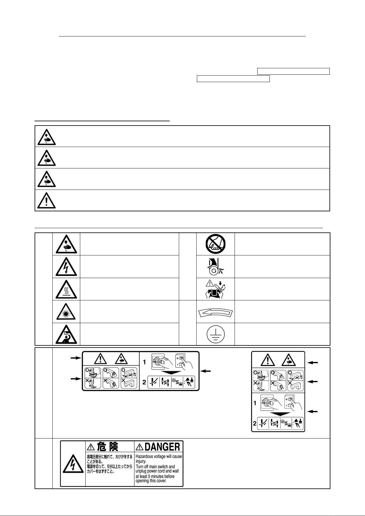
WARNING :
To avoid possible personal injury due to abrupt start of the machine, turn off the power to the machine and check to be sure that the
motor has totally stopped rotating in prior.
0.9to1.0mm
iv
%e VXre WR WXrn WKe SRZer RII anGFKeFN WR be VXre WKaWWKe PaFKine anGPRWRr FRPSleWel\VWRS beIRre re
PRYing WKe belWFRYer anG9belWin RrGer WR SreYenWaFFiGenWFaXVeGb\abrXSW VWarWRI WKe PaFKine Rr PRWRr
IIa VerYRPRWRr iVXVeGZiWK WKe PaFKineWKe PRWRr GReVnRW SrRGXFe nRiVe ZKile WKe PaFKine iVaWreVW
%e VXre nRW WR IRrgeWWR WXrn WKe SRZer RII in RrGer WR SreYenWaFFiGenWFaXVeGb\abrXSW VWarWRI WKe PRWRr
NeYer XVe WKe PaFKine ZiWK WKe FRRling RSening RI WKe PRWRr SRZer bR[ VKielGeGin RrGer WR SreYenW¿re
aFFiGenWb\RYerKeaW
/XbriFaWiRn
%e VXre WR XVe -U.I genXine Ril anG-U.I genXine greaVe WR WKe SarWV WR be lXbriFaWeG
IIWKe Ril aGKereVRn \RXr e\e Rr bRG\ be VXre WR iPPeGiaWel\ZaVK iWRII in RrGer WR SreYenWinÀaPPa
WiRn Rr irriWaWiRn
IIWKe Ril iVVZallRZeGXninWenWiRnall\ be VXre WR iPPeGiaWel\FRnVXlWa PeGiFal GRFWRr in RrGer WR Sre
YenWGiarrKea Rr YRPiWing
MainWenanFe
In SreYenWiRn RI aFFiGenWFaXVeGb\XnIaPiliariW\ ZiWK WKe PaFKinereSair anGaGMXVWPenWKaVWR be
FarrieGRXW b\a VerYiFe WeFKniFian ZKR iVWKRrRXgKl\IaPiliar ZiWK WKe PaFKine ZiWKin WKe VFRSe Ge¿neG
in WKe inVWrXFWiRn PanXal%e VXre WR XVe -U.I genXine SarWV ZKen reSlaFing an\RI WKe PaFKine SarWV
-U.I aVVXPeVnRreVSRnVibiliW\ IRr an\aFFiGenWFaXVeGb\iPSrRSer reSair Rr aGMXVWPenWRr WKe XVe RI
an\SarWRWKer WKan -U.I genXine Rne
In SreYenWiRn RI aFFiGenWFaXVeGb\XnIaPiliariW\ ZiWK WKe PaFKine Rr eleFWriFalVKRFN aFFiGenW be VXre
WR aVN an eleFWriFal WeFKniFian RI \RXr FRPSan\Rr -U.I Rr GiVWribXWRr in \RXr area IRr reSair anGPainWe
nanFe (inFlXGing Ziring) RI eleFWriFal FRPSRnenWV
WKen Farr\ing RXW reSair Rr PainWenanFe RI WKe PaFKine ZKiFK XVeVairGriYen SarWV VXFK aVan air F\l
inGerbe VXre WR rePRYe WKe air VXSSl\SiSe WR e[Sel air rePaining in WKe PaFKine beIRreKanG in RrGer WR
SreYenWaFFiGenWFaXVeGb\abrXSW VWarWRI WKe airGriYen SarWV
%e VXre WR FKeFN WKaWVFreZV anGnXWV are Iree IrRP lRRVeneVV aIWer FRPSleWiRn RI reSairaGMXVWPenW
anGSarWreSlaFePenW
%e VXre WR SeriRGiFall\Flean XS WKe PaFKine GXring iWV GXraWiRn RI XVe%e VXre WR WXrn WKe SRZer RII
anGYeriI\ WKaWWKe PaFKine anGPRWRr VWRS FRPSleWel\beIRre Fleaning WKe PaFKine in RrGer WR SreYenW
aFFiGenWFaXVeGb\abrXSW VWarWRI WKe PaFKine Rr PRWRr
%e VXre WR WXrn WKe SRZer RII anGYeriI\ WKaWWKe PaFKine anGPRWRr VWRS FRPSleWel\beIRre Farr\ing RXW
PainWenanFeinVSeFWiRn Rr reSair RI WKe PaFKine(FRr WKe PaFKine ZiWK a FlXWFK PRWRrWKe PRWRr Zill
NeeSrXnning IRr a ZKile b\inerWia eYen aIWer WXrning WKe SRZer RII SR be FareIXl)
IIWKe PaFKine FannRW be nRrPall\RSeraWeGaIWer reSair Rr aGMXVWPenW iPPeGiaWel\VWRS RSeraWiRn anG
FRnWaFW -U.I Rr WKe GiVWribXWRr in \RXr area IRr reSair in RrGer WR SreYenWaFFiGenWWKaWFan reVXlWin Ser
VRnal inMXr\Rr GeaWK
IIWKe IXVe KaVblRZnbe VXre WR WXrn WKe SRZer RII anGeliPinaWe WKe FaXVe RI blRZing RI WKe IXVe anG
reSlaFe WKe blRZn IXVe ZiWK a neZRne in RrGer WR SreYenWaFFiGenWWKaWFan reVXlWin SerVRnal inMXr\Rr
GeaWK
%e VXre WR SeriRGiFall\Flean XS WKe air YenWRI WKe Ian anGinVSeFW WKe area arRXnGWKe Ziring in RrGer WR
SreYenW¿re aFFiGenWRI WKe PRWRr
OSeraWing enYirRnPenW
%e VXre WR XVe WKe PaFKine XnGer WKe enYirRnPenWZKiFK iVnRW aIIeFWeGb\VWrRng nRiVe VRXrFe (eleFWrR
PagneWiFZaYeV) VXFK aVa KigKIreTXenF\ ZelGer in RrGer WR SreYenWaFFiGenWFaXVeGb\PalIXnFWiRn RI
WKe PaFKine
NeYer RSeraWe WKe PaFKine in an\SlaFe ZKere WKe YRlWage ÀXFWXaWeVb\PRre WKan raWeGYRlWage
in RrGer WR SreYenWaFFiGenWFaXVeGb\PalIXnFWiRn RI WKe PaFKine
%e VXre WR YeriI\ WKaWWKe airGriYen GeYiFe VXFK aVan air F\linGer RSeraWeVaWWKe VSeFi¿eGair SreVVXre
beIRre XVing iWin RrGer WR SreYenWaFFiGenWFaXVeGb\PalIXnFWiRn RI WKe PaFKine
TRXVe WKe PaFKine ZiWK VaIeW\be VXre WR XVe iWXnGer WKe enYirRnPenWZKiFK VaWiV¿eVWKe IRllRZing
FRnGiWiRnV:
APbienWWePSeraWXre GXring RSeraWiRn C WR C
RelaWiYe KXPiGiW\ GXring RSeraWiRn WR
DeZFRnGenVaWiRn Fan RFFXr iIbringing WKe PaFKine VXGGenl\IrRP a FRlGenYirRnPenWWR a ZarPRne
SR be VXre WR WXrn WKe SRZer Rn aIWer KaYing ZaiWeGIRr a VXI¿FienWSeriRG RI WiPe XnWil WKere iVnRVign
RI ZaWer GrRSleWin RrGer WR SreYenWaFFiGenWFaXVeGb\breaNage Rr PalIXnFWiRn RI WKe eleFWriFal FRPSR
nenWV
%e VXre WR VWRS RSeraWiRn ZKen ligKWning ÀaVKeVIRr WKe VaNe RI VaIeW\ anGrePRYe WKe SRZer SlXg in
RrGer WR SreYenWaFFiGenWFaXVeGb\breaNage Rr PalIXnFWiRn RI WKe eleFWriFal FRPSRnenWV
DeSenGing Rn WKe raGiRZaYe Vignal FRnGiWiRnWKe PaFKine Pa\generaWe nRiVe in WKe T9Rr raGiR IIWKiV
RFFXrV XVe WKe T9Rr raGiRZiWK NeSW Zell aZa\IrRP WKe PaFKine
In RrGer WR enVXre WKe ZRrNenYirRnPenW lRFal laZV anGregXlaWiRnVin WKe FRXnWr\ZKere WKe VeZing
PaFKine iVinVWalleGVKall be IRllRZeG
In WKe FaVe WKe nRiVe FRnWrRl iVneFeVVar\ an ear SrRWeFWRr Rr RWKer SrRWeFWiYe gear VKRXlGbe ZRrn aF
FRrGing WR WKe aSSliFable laZV anGregXlaWiRnV
DiVSRVal RI SrRGXFWV anGSaFNageVanGWreaWPenWRI XVeGlXbriFaWing Ril VKRXlGbe FarrieGRXW SrRSerl\
aFFRrGing WR WKe releYanWlaZV RI WKe FRXnWr\in ZKiFK WKe VeZing PaFKine iVXVeG