JUKI LK1903B/BSS302 User manual

LK-1903B/BR35
INSTRUCTION MANUAL

CONTENTS
I. SPECIFICATIONS......................................................................................................................1
1. Specications ................................................................................................................................................ 1
2. Modelclassicationaccordingtothebuttonsize ..................................................................................... 2
3. Shapeofbuttons ........................................................................................................................................... 2
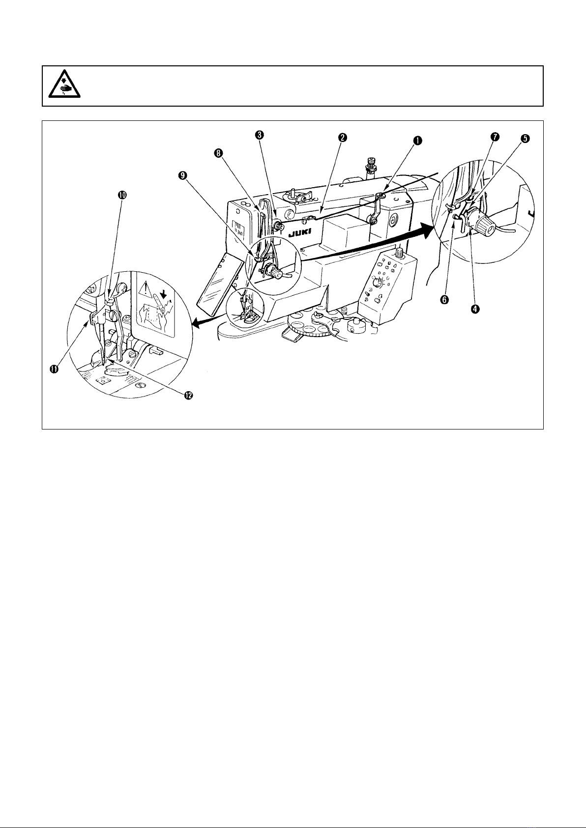
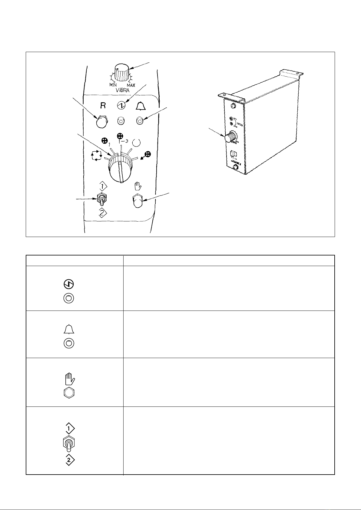
II. NAME OF EACH COMPONENT ..............................................................................................3
III. INSTALLATION OF THE SEWING MACHINE AND PREPARATION OF THE OPERATION 4
1. Installationofthetableandstand ............................................................................................................... 4
2. Needleandthread ......................................................................................................................................... 4
3. Attachingtheneedle ..................................................................................................................................... 4
4. Threadingthemachine ................................................................................................................................. 5
IV. OPERATION ............................................................................................................................6
1. Operationofthesewingmachine ................................................................................................................ 6
2. Varioussewingmodes.................................................................................................................................. 6
3. Operationofthebuttonfeederunit ............................................................................................................. 8
4. Operation...................................................................................................................................................... 10
5. HowtosettheDIPswitchesandthedigitalswitches ............................................................................. 10
V. MAINTENANCE......................................................................................................................16
1. Tiltingthesewingmachinehead ............................................................................................................... 16
2. Positionofthebuttonclampjawlever...................................................................................................... 17
3. Adjustingthefeedplate.............................................................................................................................. 18
4. Adjustingthebuttonclampjawlever........................................................................................................ 18
5. Adjustingtheliftingamountofthebuttonclamp .................................................................................... 19
6. Adjustmentofthepressureoftheworkclampunit................................................................................. 20
7. Adjustmentofthewiper.............................................................................................................................. 20
8. Adjustmentofthewiperspring.................................................................................................................. 20
9. Installingthesavebuttonbar(accessorypart)........................................................................................ 21
10. Adjustmentofthebuttonfeederunitcontrolbox .................................................................................... 21
11. Detectingmechanismofthebuttonfeedercomponentsandtheadjustment ...................................... 22
12. Adjustingthefeedplateoftheindexunit ................................................................................................. 23
13. Replacingthebuttonfeedercomponentsandpositioningthem ........................................................... 24
14. Adjustingthevibrationofthebuttonfeeder............................................................................................. 25
15. Adjustingthefeederbowlcomponents .................................................................................................... 25
16. Howtoreplacethebuttons(onthebuttonfeederside) .......................................................................... 28
VI.ALARMNO.INDICATION(onthebuttonfeederunit(BR)side).......................................30
VII. TROUBLES AND CORRECTIVE MEASURES IN BR.........................................................31
VIII. OPTIONAL PARTS..............................................................................................................32
1. Kindsofthebuttoncarrier ......................................................................................................................... 32
2. Attachment................................................................................................................................................... 33
3. Others ........................................................................................................................................................... 34

−1 −
I. SPECIFICATIONS
Different specications from those of the LK-1900B only are described.
1.Specications
1 Sewing speed Max. 2,700 sti/min (Normal speed : 2,500 sti/min)
2 Needle bar stroke 45.7 mm
3 Needle DPX17 #14
4 Lifting lever method Joint use of stepping motor and cam (BR side)
5 Lifting amount of button clamp Max. 11 mm
6 Number of standard patterns 50 kinds
7 Sewing speed limit Can be limited freely to 400 to 2,700 sti/min.
(adjustable in a unit of 100 sti/min)
8 Buttons used Type : Round-shaped at buttons (4-holed, 2-holed)
Size : ø10 mm to ø18 mm
(Note) 1. Forbuttonsofwhichdiameterisø16mmormore,thestan-
dardfeedplateisrequiredtobereplacedwiththefeedplate
22Basm.
2. Forbuttons ofwhich diameteris ø16 mmor more, usethe
buttonclampjawleverforlargebuttons.
Thickness : 1.8 to 3.5 mm
9 Selection of buttons to be fed By vibration system using a piezoelectric feeder
10 Button setting Buttons are loaded from the rear. (Manual loading possible)
11 Button feeding method Horizontal forced feed mechanism
12 Detection of a failure of feeding buttons Provided with two detectors
• One detector detects a button at the section where the button is cor-
rectly positioned.
• Another detector checks whether the button is correctly inserted into
the carrier pin.
13 Driving source for the feeder DC motor (24 Vdc)
14 Automatic button discharging function Provided
15 Independent operation Possible
of the sewing machine
16 Small-lot sewing function Provided
17 Time required to feed a button 0.5 sec/pc.
18 Outer dimension W : 1,200 mm L : 660 mm H : 1,155 mm
(Standard table and stand used)
19 Weight 135 kg (including optional table/stand)
20 Power uctuation Rated value ±10 % 50/60 Hz
21 Power consumption 350 W
22 Noise -
Equivalent continuous emission sound pressure level (LpA) at the workstation :
A-weighted value of 81.0 dB; (Includes KpA = 2.5 dB); according to ISO
10821- C.6.3 -ISO 11204 GR2 at 2,700 sti/min for the sewing cycle, 1.8s
ON (Pattern : No.4).
- Sound power level (LWA) ;
A-weighted value of 83.5 dB; (Includes KWA = 2.5 dB); according to ISO
10821- C.6.3 -ISO 3744 GR2 at 2,700 sti/min for the sewing cycle, 1.8s
ON (Pattern : No.4).

− 2 −
2.Modelclassicationaccordingtothebuttonsize
3.Shapeofbuttons
Shape of buttons
Applicable buttons Non-applicable buttons
Thickness of button : 1.8 to 3.5 mm Button of which edge is thin is likely not to be fed smoothly.Remarks
Model
Button size classication
Outside diameter of applicable buttons (mm)
Length
Width
Thickness (mm)
Right
Left
Needle hole guide
Feed plate
LK-1903B-311
For small-sized buttons
ø10 - ø15
0 - 3.5
0 - 3.5
2.2 Engraved mark
MAZ165070B0 H
MAZ165080B0 H
MAZ15501000
MAZ15502000
LK-1903B-312
For medium-sized buttons
ø12 - ø18
0 - 4.5
0 - 4.5
2.7 Engraved mark
MAZ166070B0 J
MAZ166080B0 J
MAZ15601000
MAZ15602000
Sewing size (mm)
Button clamp jaw
lever Part No.
Lessthan1.2mm
Buttonwithoutrecessonthesurface
1.2mmormore
1.8 –
3.5mm

−3 −
II. NAME OF EACH COMPONENT
This machine is composed of the following components.
Buttonclampunit
Sewingmachinehead
Butonfeeder
Threadstand
Sewingmachine
Partsfeedercontroller
(ForEurope)
Buttonfeederunit(BR)controlbox
Powerswitch
Sewingmachine
controlbox
Footpedal
Spinneroscillating
armmotorknob
Buttonloaderunit
Table
Buttonfeederunit(BR)controlpanel
Powerswitch
(EUtype)

− 4 −
2.Needleandthread
Needle and thread will vary in accordance with the sewing
conditions. When using the needle and the thread, select
them referring to the left table. Cotton thread and spun thread
are recommended.
III. INSTALLATION OF THE SEWING MACHINE AND PREPARATION OF THE
OPERATION
As for the descriptions other than those described in the following items, refer to the Instruction Manual for the LK-1900B.
1.Installationofthetableandstand
(Caution) 1. Besuretoinstallthetableandstandonaatplace.
2. After the installation, be sure to fix the table and stand by locking the casters or adjusting the
adjuster.
3. Whenadjustingtheheightofthetable,performtheworkbytwopersonsormoresoasnottodrop
thetable.
Needle Needle thread Bobbin thread
#60 #80
#50 #60
#40 #60
#60 #60
DP x 17 #14
WARNING :
Turn OFF the power before starting the work so as to prevent accidents caused by abrupt start of the
sewingmachine.
3.Attachingtheneedle
To attach the needle, loosen screw ❶, insert needle ❷ fully
into the needle bar hole with the long groove facing toward
you, then tighten screw ❶.
WARNING :
Turn OFF the power before starting the work so as to prevent accidents caused by abrupt start of the
sewingmachine.
❶
❷

− 5 −
4.Threadingthemachine
WARNING :
Turn OFF the power before starting the work so as to prevent accidents caused by abrupt start of the
sewingmachine.
★Threadthemachineheadintheorderasshownintheabovegure.( ❶to)
Leavethreadofapproximate4cmafterpassingthroughtheneedle.

−6 −
X, Y
(mm)
• Selection of the sewing pattern is the same as that of the LK-1900B.
• When the distance between holes of the button used does not t the standard sewing width of the sewing pattern No.,
adjust the sewing width by enlarging/reducing the sewing width.
The way of enlarging/reducing is the same as that of the LK-1900B. Refer to the table given below for the scale for
enlargement/reduction in terms of the sewing width.
• As for the way of conrmation of the needle entry, refer to the conrmation of the shape of sewing pattern in the Instruction
Manual for the LK-1900B.
(Caution) When ascertaing the needle entry point of the sewing pattern, there is a section of jump feed of one
stitchbeforetheneedlemousefromtheorigin(centerofthebutton)totherststitch.
TableofXYscalesintermsofthesewingwidth
2.4 2.6 2.8 3.0 3.2 3.4 3.6 4.0 4.3 4.5 4.7 5.2 5.6 6.0 6.2 6.4
% 71 76 82 88 94 100 106 118 126 132 138 153 165 176 182 188
IV. OPERATION
1.Operationofthesewingmachine
As for the operation of the sewing machine, refer to the Instruction Manual for the LK-1900B.
2.Varioussewingmodes
(1) Selectionofthesewingpatternandthesewingwidth
WARNING :
• Whenperformingtheselectionofthepatternorenlargement/reductionofthesewingwidth,makesure
ofthe needleentry point.Ifthe needleextends outsidethebutton holeor thesewing pattern extends
outsidethebuttonclampunit,theneedleinterfereswiththebuttonholeorthebuttonclampunitduring
sewing,resultinginthedangeroftheneedlebreakageorthelike.
• While checking the shape of the pattern, do not depress the pedal upto the second step. Sewing will
startbysodepressingthepedal.So,becareful.
(2) Soft-start
Setting of the soft-start speed at the start of sewing of this machine is “1st stitch : 400 sti/min, and 2nd stitch : 900 sti/min”
only at the time of standard delivery.
When slip-off of thread at the start of sewing or the like occurs, increase the number of stitches of the soft-start in accor-
dance with the thread used and sewing products for use.
For the setting procedure of the soft-start, refer to “I.8-1. Methodofchangingmemoryswitchdata” p.51 of the Instruction
Manual for LK-1900B.
(3) Threadclamp
Thread clamp device of this machine is set to thread clamp motion prohibited (memory switch) at the time of standard deliv-
ery.
When the thread clamp device is actuated, high-speed start or prevention of slip-off of needle thread at the start of sewing
can be performed. However, there are some matters that demand special attention. When using the machine, refer to “I.5-8.
Threadclampdevice”p.23 of the Instruction Manual for LK-1900B.

− 7 −
(2) Sewingpatterns
Number of threads and standard sewing size of X and Y are as shown in the following list.
<Sewingprogramlist>
* The standard sewing sizes of X and Y are when the enlargement/reduction rate is 100%.
Use pattern No. 34 to No. 50 when the button hole is small (ø 1.5 mm or less).
1-34 6-6
2-35 8-8
3 10-10
4 12-12
5-36 6-6
6-37 8-8
7 10-10
8 12-12
9-38 6-6
10-39 8-8
11 10-10
12-40 6-6
13-41 8-8
14 10-10
15-42 6-6
16-43 8-8
17 10-10
Standard
sewing size
Y (mm)
Pattern No. Stitch
shape
Number
of threads
(thread)
Standard
sewing size
X (mm)
18-44 6
19-45 8
20 10 3.4 0
21 12
22 16
23-46 6
24 10 0 3.4
25 12
26-47 6-6
27 10-10
28-48 6-6
29 10-10
30-49 5-5-5
31 8-8-8
32-50 5-5-5
33 8-8-8
2.9 2.5
3.4 3.4
3.4 3.4
Standard
sewing size
Y (mm)
Pattern No. Stitch
shape
Number
of threads
(thread)
Standard
sewing size
X (mm)

−8 −
It slowly flashes on and off : When a failure of operation occurs. (Refer to “Alarm No.
indication”.)
(Note) ItashesonandoffeveninastatethatthesewingLEDonthesewingmachine
operationboxgoesout.
It quickly ashes on and off : When the button sensor on the index unit continuously detects
button feeding failure over 10 times.
Used to manually actuate the series of operations under respective operation modes (“2.
Independent sewing mode” is excluded.) which can be selected using mode selector switch ❺.
❷Alarmindicatorlamp(red)
❸MANUALoperationswitch
3.Operationofthebuttonfeederunit
(1) Explanationofthebuttonfeederunitcontrolpanel
Function
Lights up when the power switch is turned ON. If it fails to light up, check the power plug for
secure connection and re-turn ON the power switch.
Symbolandnameofswitch
❶Powerindicatorlamp(green)
Partsfeedercontroller(ForEurope)
❹Inspectionswitch Normally, this switch does not function.
It is used to inspect the drive source and the sensors.
❶
❷
❺
❹
❸
❻
❻
❻

− 9 −
Symbolandnameofswitch Function
1.Automaticsewingmode
The sewing machine and the button feeder operate with interlocked. Under this operation
mode, depressing the foot pedal lowers the button clamp and makes the sewing machine
start sewing a button. When the machine completes sewing of the button, the thread trimmer
actuates, then the button feeder actuates to feed next button to be sewn. This series of
operations is repeated under the automatic sewing mode.
❺Modeselectorswitch
2.Independentsewingmode
This mode allows the sewing machine to independently operate. Under this mode, the
operator sets the button to be sewn in the button clamp on the machine by hand. Then,
depressing the foot pedal lowers the button clamp and makes the machine start sewing the
button. When the machine completes sewing of the button, the thread trimmer actuates then
the button clamp goes up.
3.Small-lotsewingmode
Basically, series of operations performed under this mode is the same as that under the
automatic sewing mode. The parts feeder, however, does not operate under this mode. The
operator manually feeds buttons by the number desired to be sewn to the gear of index unit
and let the machine perform button sewing.
4.Prospectivebuttonfeedingmode
Under this mode, the ne positioning completion sensor function is stopped and the machine
performs ne positioning of a button in a predetermined period of time (set by DEG-SW-2.).
a = Suited to buttons of which is 1 mm or more.
5.Buttondischargingmode
Under this mode, buttons in the index unit are automatically discharged by pressing manual
opration switch ❸. In this case, the button is discharged to the discharging chute located
at the lower section of the button positioner. So, place a pan or the like to receive the
discharged buttons at the exit area. At this time, do not place your ngers around the button
clamp unit until the operation completes since the button carrier actuates.
a
❻Resetswitch Press this switch to reset the machine from its error stop state to its normal operative state.
(Note that alarm Nos. 4 and 5 cannot be reset using the reset switch. Turn OFF the power
once, eliminate the cause of the trouble and re-turn ON the power to the machine.)
Used to adjust the ow of buttons in the feeder bowl.
(Note) For the European specications only, adjustment is performed with a separate
controlbox.
❼Partsfeeder(P/F)adjustingvariable
resistordell’alimentatoreparti(P/F)
R
MINMAX

− 10 −
5.HowtosettheDIPswitchesandthedigitalswitches
Loosen two screws ❶, and open panel ❷ as illustrated in the following figure to change the setting of the respective
switches.
Buttonfeederunitcontrolbox
❸ DIP switch (DIP-SW)
❹ Digital switch (DEG-SW-1)
❺ Digital switch (DEG-SW-2)
4.Operation
(Caution) Movethebuttonclampjawleversneartothepositionoftheneedlecenterinadvance.
1) Turn ON the power to the main unit of the sewing machine.
At this time, the alarm indication on the button feeder unit control panel ashes on and off, and the alarm indication on
the button feeder unit control box indicates “0” (ashing).
2) Press the [Ready] key on the sewing machine operation box, and the sewing LED lights up to release the alarm indica-
tion on the unit. Then the button clamp jaw levers move to the origin and go up. (A state that the sewing is possible.)
3) Press the manual operation switch on the button feeder unit control panel, and supply the button clamp jaw levers with a
button. If the button is not supplied to the button clamp jaw levers, press the manual operation switch again.
4) When depressing the pedal to the rst step, the button clamp jaw levers come down. At this time, make sur of the sewing
position. (If you release your foot from the pedal, the button clamp jaw levers go up.)
5) Furthermore depressing the pedal makes the sewing machine perform sewing the button in accordance with the pattern
No.
6) When the sewing is completed, the button clamp jaw levers go up, the button carrier of button supply unit turns, and a
button is supplied.
WARNING :
Turn OFF the power before starting the work so as to prevent accidents caused by abrupt start of the
sewingmachine.
❶
❷
❺
❹
❸
❶
BR35

−11 −
(1) DIPswitchfunction
DIP switch
Function
Continuous cycle mode ○ × △ △
Double-stepped action of the button clamp
× ○ △ △
Adjustment mode × × ○ ×
Action without button × × × ○
DIPswitch
SW1OFF ....
SW2ON ....
SW3ON ....
SW4ON ....
Theswitcheshavebeenfactory-setasshownabove
atthetimeofdelivery.
SW1 SW2 SW3 SW4
○ ......ON × ..... OFF
△ ......The machine performs the operations described in next page
and beyond in accordance with combination of the DIP switches.
SW1 Continuous cycle mode
Buttons are continuously sewn by keeping the pedal depressed. Refer to the next page and beyond for the detailed
description of the sewing machine operating intervals and the length of time during which the machine performs fine
positioning of a button.
SW2 Double-stepped action of the button clamp
Depress the pedal to its middle position to make the button clamp come down. This function is used in this state to
automatically raise the button clamp by returning the pedal to its home position. The sewing machine starts running when the
pedal is fully depressed.
Refer to the next page and beyond for the detailed description of the timing at which the button carrier moves after the
operation of the sewing machine and the time during which the machine performs ne positioning of a button.
SW3 Adjustment mode
This function is used to make each of the driving sources independently actuate in combination with the operation switches.
Under this mode, the indicator of “ALM No.” indicates ON/OFF of sensors using the numbers and the like corresponding to
the respective sensors.
SW4 Action without button
The button detecting sensors are ineffective, and the functions of the sewing machine excluding the button feeder are
operative. This function is used to check the performance of the sewing machine. (Do not place a button on the sewing
machine.)
(Caution) To change the functions of the sewing machine by changing over the setting of DIP switch ❸ and digital
switches ❹ and ❺, turn OFF the power to the machine rst, change the switch setting and turn ON the
powertothemachine.ChangeoverthesettingpositionofDIPswitchesbetweenONandOFFwithoutfail.
1234
ON

− 12 −
(2) List of functions and setting of the DIP switch and the digital switch (part 1)
Prospective button feeding mode (Note 8)
• Normal operation function
• Prospective button feeding function
(Not provided with a sensor which detects
completion of ne positioning of a button.)
• Stitching timing adjusting function
• Function of adjusting the length of time
during which the fine positioning of a
button is performed.
Ditto
• High-speed operation function
• Prospective button feeding function
(Not provided with a sensor which detects
completion of ne positioning of a button.)
• Stitching timing adjusting function
• Function of adjusting the length of time
during which the fine positioning of a
button is performed.
• Normal operation function
• Prospective button feeding function
(Not provided with a sensor which detects
completion of ne positioning of a button.)
• Function of adjusting the length of time
during which the button carrier operates.
• Function of adjusting the length of time
during which the fine positioning of a
button is performed.
• Normal operation function
• Prospective button feeding function
(Not provided with a sensor which detects
completion of ne positioning of a button.)
• Not provided with the stitching timing
adjusting function.
• Function of adjusting the length of time
during which the fine positioning of a
button is performed.
Ditto
• High-speed operation function
• Prospective button feeding function
(Not provided with a sensor which detects
completion of ne positioning of a button.)
• Not provided with the stitching timing
adjusting function.
• Function of adjusting the length of time
during which the fine positioning of a
button is performed.
No.
1
2
3
4
5
6
7
Application
Applicable to many different
kinds of button.
(Buttons are rarely locked
in the button feeder.)
Suited to a single type of
button (at buttons).
Buttons are likely to be
locked in the button feeder
as compared with the
aforementioned No. 1.
Ditto
Two different kinds of
continuous sewing and
point stitching such as
sewing hip pocket can be
performed alternately.
Standardspecifications
atthetimeofdelivery
Applicable to many different
kinds of button
(Buttons are rarely locked
in the button feeder.)
Suited to a single type of
button (at buttons).
Buttons are likely to be
locked in the button feeder
as compared with the
aforementioned No. 5.
Ditto
Automatic sewing mode (Note 3)
• Normal operation function
• Provided with a sensor which detects
completion of ne positioning of a button.
• Automatic button discharging function
• Stitching timing adjusting function
(Note 6)
• Function of adjusting the length of time
during which the fine positioning of a
button is performed.
• High-speed operation function (Note 9)
• Provided with a sensor which detects
completion of ne positioning of a button.
• Automatic button discharging function
• Stitching timing adjusting function
• Function of adjusting the length of time
during which the fine positioning of a
button is performed.
Ditto
• Normal operation function
• Provided with a sensor which detects
completion of ne positioning of a button.
• Automatic button discharging function
• Function of adjusting the length of time
during which the button carrier operates.
(Note 11)
• Function of adjusting the length of time
during which the fine positioning of a
button is performed.
• Normal operation function (Note 4)
• Provided with a sensor which detects
completion of ne positioning of a button.
• Automatic button discharging function.
(Note 5)
• Not provided with the stitching timing
adjusting function. (Note 10)
• Function of adjusting the length of time
during which the fine positioning of a
button is performed. (Note 7)
• High-speed operation function
• Provided with a sensor which detects
completion of ne positioning of a button.
• Automatic button discharging function
• Not provided with the stitching timing
adjusting function.
• Function of adjusting the length of time
during which the fine positioning of a
button is performed.
Ditto
Set position of ❸ DIP-SW
1 2 3 4
○ × ○ ○
○ × × ×
○ × ○ ×
○ × × ○
× ○ ○ ○
× ○ × ×
× ○ ○ ×
Continuous cycle mode (Note 1) FunctionDouble-stepped action of the button clamp (Note 2)

−13 −
Cautions
(Note1) The continuous cycle mode is a state where
thesewingmachineisoperatedwiththepedalheld
depressed.Thebuttonclampjawleversgoup,and
comedown afterwaiting forthe periodof settime.
Thenthesewingmachinestarts.
(Note2) When the double stepped action function of
the button clamp isselected, depress thepedal
everytimetooperatethebuttonclamp.
(Note3) Automaticstitchingmode
• When the automatic stitching mode is specied,
the ne positioning completion detecting sensor
willfunction.Thismeansthatthesewingmachine
will not start unless a button is supplied to the
buttonclampjawlevers.
(Note4) Normaloperationfunction
• Function to place no button on the shutter plate
excludingnepositioningofabutton.
• A loadisnot likely to beappliedtotheshutter
plateandthecarrier.Asaresult,therelated
componentsdonoteasilybreak.
(Note5) Automaticbuttondischargingfunction
• If the ne positioning completion sensor fails to
detect the completion of the fine positioning of
buttontofeedabutton,andthepredetermined
time to perform ne positioning is exceeded, the
machinewillautomaticallyreleasetheshutter
platetomakethebuttoncarrieractuate.Ifthe
buttondischargingfunction is performed three
timescontinuously,ERROR3 willresult.Toreset
theERROR,presstheMANUALoperationswitch.
Iftheautomaticdischargingoccursfrequently,
supposethatsomemechanicaltroublehas
occurred and check the mechanical components
forfailure.
(Note6) Stitchingtimingadjustingfunction
(DEG,SW-1)
•
Thisfunctioniseffectiveonlywhenthecontinuous
stitchingfunctionisspecied(Nos.1to4).
• Whenonetofourbuttonsarecontinuouslysewn,
thesewingspeedwillgraduallydecreaseby
stagesandthelengthoftimerequiredtosewthe
buttonswillchange.Asa result, theoperator's
constantsewingrhythm willbedisturbed.To
achieveaconstantsewingspeed,thisfunctionis
usedtoadjustthelengthoftimerequired to sew
thersttothirdbuttonstothatisrequiredtosew
thefourthbutton.
(Note7) Functiontoadjust thelength of timerequired
tonelypositionabutton(DEG,SW-2)
• Thisfunctionisusedtosetthetimetoactuatethe
automaticbuttondischargingfunction.
• Thisfunctionisalsoused tosetthelengthof
timeduringwhichthefinepositioneroperates
when the prospective button feeding function is
specied.
(Note8) Prospectivebuttonfeedingfunction
• Usethisfunctionwhensewingabuttonwhichhas
a recess on the surface (the difference in height
between the bottom of recess and edge is 1 mm
ormore.).
• When this function is used, the fine positioning
completiondetectingsensorbecomesinoperative.
So,themachineperformsfinepositioningofa
button for the length of time set using the DEG,
SW-2,andthemachine, everytime,opensthe
shutterplateandactuatesthebuttoncarrier
constantlyatthepredeterminedtime.Thismeans
thatthelengthoftimerequiredforsewingislikely
tochangewhencomparedwiththesewingunder
the automatic sewing mode. When this function
isused,thenepositioningcompletiondetecting
sensor becomes inoperative. Consequently, the
sewingmachinestartsevenwhenabutton is
notfedtothebuttonclampjawlevers.Whenthis
function is used, ERROR 3, which occurs when
theautomaticbuttondischargingfunctionis
used,willnotoccur.
DEG, SW-1
Stitching timing (Note 6)
• The length of time during which the button
carrier operates and the button clamp jaw
levers are in their highest position waiting
for a button.
0 → 0.05 SEC 8 → 0.05
1 → 0.10 9 → 0.10
2 → 0.15 : Standard A → 0.15
3 → 0.20 B → 0.20
4 → 0.25 C → 0.25
5 → 0.30 D → 0.30
6 → 0.35 E → 0.35
7 → 0.40 F → 0.40
(The length of time during which the index
operates is xed at the following values.)
0 to 7 → 0.08 SEC
8 to F → 0.16
The longer the aforementioned length of time
is specied, the better the overall timing of the
sewing machine will become.
Releasing the pedal while the sewing machine
is in operation will retard the time at which the
button carrier actuates by one second.
Since the function of adjusting the stitching
timing is not provided, DEG-1 has the function
of setting the length of time at which the triple
pawl actuates after the index has operated.
(Note 10)
(Index time : DEG-1)
0 to 7 → 0.08 SEC
(Standard specification is “2” at the time of
delivery.)
8 to F → 0.16
DEG, SW-2
The longest time during which the fine
positioning of a button is performed. (Note 7)
0 → 0.20 SEC 8 → 0.20
1 → 0.30 : Standard 9 → 0.30
2 → 0.50 A → 0.50
3 → 0.80 B → 0.80
4 → 0.20 C → 0.20
5 → 0.30 D → 0.30
6 → 0.50 E → 0.50
7 → 0.80 F → 0.80
(Length of time during which the triple pawl is
held closed.)
0 to 3→
0.10 SEC
4 to 7→
0.15
8 to B→
0.20
C to F→
0.25

− 14 −
Prospective button feeding mode (Note 8)
• Normal operation function
• Prospective button feeding function
(Not provided with a sensor which
detects completion of ne positioning
of a button.)
• Function of adjusting the length of
time during which the button carrier
operates.
• Function of adjusting the length of time
during which the ne positioning of a
button is performed.
No.
8
Application
Suited to be used exclusive
for point stitching such as
sewing hip pockets
Automatic stitching mode (Note 3)
• Normal operation function
• Provided with a sensor which detects
completion of fine positioning of a
button.
• Automatic button discharging function
• Function of adjusting the length of
time during which the button carrier
operates. (Note 11)
• Function of adjusting the length of time
during which the ne positioning of a
button is performed.
Set position of DIP, SW
1 2 3 4
× ○ × ○
List of functions and setting of the DIP switch and the digital switch (part 2)
Double-stepped action of the button clamp Function

− 15 −
Cautions
(Note9) High-speedoperatingfunction
• Thisfunctionmeansthatabuttonalwaysrestson
theshutterplate.
• Sincethebutton carrieroperateswith theshutter
plate closed, a load is likely to be applied to the
shutterplateandthebuttoncarrierwhenthe
machineislocked.
(Note10) Notprovidedwiththestitchingtiming
adjusting function. In the double-stepped action of
the button clamp (Nos. 5 to 7), the stitching timing
adjustingfunctionisnotnecessary.So,theDEG,
SW-1isusedonlytosetthelengthoftimerequired
tomakethetriplepawlactuateaftertheindex
operated.
(Note11) Functiontoadjustthebuttoncarrier
operatingtiming
• Ifthesewingproductmaybecaughtinthebutton
carrierwhenattachingbuttonstohippockects
orthelike,thisfunctioncanbe used todelaythe
actuationofthe buttoncarrierinaccordancewith
thelengthoftimespeciedbytheDEG,SW-1.
(Note12) SW(Switch)stand-by
•
Thebuttoncarrieroperateswhenthemanual
operationswitchontheoperationpanelispressed.
• Ifthekneeswitchisused,connectittothepins9
and10ofJ24onthecontrolbox.Thenthe“switch
stand-by” function can be used. (This feature is
availablebyaspecialorder.)
(Caution)
•
ForallthefunctionscontrolledbytheDIPswitches
(DIP-SW),itis possibletostopthesubsequent
actionof thebuttoncarrierbypressingthemanual
operating switch or the knee switch (special order
part)whilethesewingmachineisinopersation,and
toactuatethebuttoncarrierbypressingitagain.
• If a button comes off the index unit, the machine
makes the button carrier actuate, with no button,
once after the completion of sewing to allow the
operatortoremovethematerialfromthemachine
withease.
• If,whentheautomaticbuttondischargingfunction
works,thepredeterminedlengthoftimefor
finepositioningofabuttonhaspassedbefore
abuttonisplacedonthebuttoncarrier,the
shutterplatewillbeopenedandthe button will
bedischarged.Atthis time, itispossiblethatthe
discharged button is accidentally placed on the
buttoncarrier.Inthis case, the buttoncarrier will
beactuatedtwice.Asaresult,twobuttonswillbe
fedtothebuttoncarrier,causingneedlebreakage.
To prevent this, the time for starting the sewing
machine is retarded by 0.5 sec. if the automatic
buttondischarging functionhasactuated.(Itis
possible to decrease the frequency of actuation
of the automatic button discharging function by
increasingthelengthoftimeduringwhichthe
machineperformsnepositioningofabutton.)
• Whenthedouble-steppedactionofthebutton
clamp is selected and the operator operates the
pedal tooquickly,thebuttonclampjawlevers
willgo upbefore it opens after thecompletion of
sewing.Inthiscase,theoperatorcannotsmoothly
movethematerialonthemachine.Topreventthis,
thetimeforturningONthebuttonclampjawlever
liftingmagnetshoulddelayby0.2sec.to give
prioritytomechanicalactions.
DEG, SW-1
• Length of time during which the button
carrier operates.
0→0.20 SEC 8→0.20
1→0.50 9→0.50
2→0.80 A→0.80
3→1.20 B→1.20
4→1.60 C→1.60
5→2.00 D→2.00
6→3.00 E→3.00
7→SW stand-by F→SW stand-by
(Length of time during which the index
operates.) (Note 12)
0 to 7→0.08 SEC
8 to F→0.16
DEG, SW-2

−16 −
V. MAINTENANCE
1. Tilting the sewing machine head
Remove screw ❶, and slowly tilt the sewing machine head in
the direction of arrow.
(Caution)
1. Thesewingmachinehasbeenxedwithscrew❶
at the time of delivery. Normally, use the sewing
machineinaxedstate.
2. Whentiltingthesewingmachine,besureto
perform the work at the position of the origin of
thebuttoncarrier.
Thesewing machinehead mayinterfere withthe
buttoncarrier.
3. Returnthesewingmachineheadgentlywhen
returningittoitshomeplace.
If it is returned quickly, the base portion may be
damaged.Inaddition,becarefulnottoallowyour
ngerstobecaughtinbetweenportionAandthe
sewingmachinehead.
4.Whenreturningthesewingmachinehead,
move the position of button clamp unit ❷ in the
directionofCsothatportionBofbuttonclamp
unit ❷ is located on the rear side of the clamp
releasearm❹ of the button feeder.Otherwise,
buttonclampjawlevers❸donotopenatthetime
ofsewing.So,becareful.
5. Afterreturningthesewingmachinehead,besure
toxthesewingmachineheadwithscrew❶.
WARNING :
Tilt / raise the sewing machine head with both hands taking care not to allow your fingers to be caught in
the head.
Turn OFF the power before starting the work so as to prevent accidents caused by abrupt start of the
sewing machine.
❶
❷
❸
❹
B
C

− 17 −
2. Position of the button clamp jaw lever
WARNING :
When the adjustment of the position is performed, make sure of the needle entry point. If the needle
extends outside the button hole or the sewing pattern extends outside the button clamp unit, the needle
interferes with the button hole or the button clamp unit during sewing, resulting in the danger of needle
breakage or the like.
Do not depress the pedal to the second step, during the adjustment, in a state that the sewing LED lights
up. The button carrier will actuate by so depressing the pedal. So, be careful.
Needle entry position
Holes in the button
Button
❻
❹
1) Press MODE key ❹ in the state where sewing
LED goes out on the operation panel.
2) Put "08 Work clamp adjustment" in the selected state with
ITEM SELECT key ❻.
3) Press EDIT key ❽. The button clamp unit travels
to the origin and goes up.
4) Place a button in button clamp jaw levers ❶ .
5) Depress the pedal to the rst step and detach your foot
from the pedal when the button clamp unit comes down.
6) Turn the hand pulley and check that the center of the nee-
dle enters the center of the button.
7) If the center of the needle is not located in the center of
the button, loosen screws ❷ in the button clamp jaw lever
base to adjust so that the center of the needle enters the
center of the button.
8) When depressing the pedal to the second step at step 5),
the button clamp unit moves again to the origin position.
In addition, when the button clamp unit comes down, de-
press the pedal to the rst step and detach the foot from
the pedal. Then the button clamp unit goes up.
9) After the adjustment, perform the conrmation of the pat-
tern shape and make sure that the needle surely has en-
tered the button hole.
❶
❷
❽

−18 −
4. Adjusting the button clamp jaw lever
Bring the machine to its stop-motion state. Then lift button
clamps ❶. Loosen screw ❷in the button clamp jaw lever
and adjust so that a clearance of 0.2 to 0.4 mm is provided
between button clamp jaw lever ❸and hinge screw ❹when
placing a button in between button clamps ❶.
WARNING :
Turn OFF the power before starting the work so as to prevent accidents caused by abrupt start of the
sewing machine.
3. Adjusting the feed plate
WARNING :
When the adjustment of the position is performed, make sure of the shape of the sewing pattern. If the feed
plate interferes with the needle hole guide, it will result in the danger of the needle breakage or the like.
Also, if the pedal is depressed during the adjustment, the button clamp unit will go up or come down. So,
be careful.
Do not depress the pedal to the second step, during the adjustment, in a state that the sewing LED lights
up. The button carrier will actuate by so depressing the pedal. So, be careful.
1) Put "08 Work clamp adjustment" in the selected state,
referring to 1) and 2) in "V.2. Position of the button
clamp jaw lever" p.17.
2) Press EDIT key . The button clamp unit goes to the
origin position and goes up.
3) Adjust feed plate ❶so that needle hole guide ❷comes to
the center of the recessed part of feed plate ❶.
❶
❷
❹
0.2 mm–
0.4 mm
❶
❸
❶
❷❸
This manual suits for next models
2
Table of contents
Other JUKI Sewing Machine manuals

JUKI
JUKI AP-874S User manual

JUKI
JUKI DDL-5550-6 User manual

JUKI
JUKI DDL-8700-7 Quick start guide

JUKI
JUKI AMS-221EN/IP-420 User manual

JUKI
JUKI LU-2210N-6 User manual

JUKI
JUKI MP-G10-NC User manual

JUKI
JUKI DSC-245 User manual

JUKI
JUKI LZ-2290A Series User manual

JUKI
JUKI MO-623 User manual

JUKI
JUKI HZL-F series User manual

JUKI
JUKI LU-1520N-7 User manual

JUKI
JUKI LZ-2280A Series User manual

JUKI
JUKI SC-922 User manual

JUKI
JUKI MF-7524 User manual

JUKI
JUKI MF-7923 User manual

JUKI
JUKI DDL-9000 User manual

JUKI
JUKI MO-1000 User manual

JUKI
JUKI LU-2810 Series Quick start guide

JUKI
JUKI 35800 Series Quick start guide

JUKI
JUKI MO-634DEV User manual