JUKI LBH-1700 Quick start guide

R
ENGINEER’S MANUAL
29339504
No.04
Electronic Buttonholing Machine
LBH-1700 Series

PREFACE
This Engineer’s Manual is written for the technical personnel who are responsible for the service and maintenance of
the machine.
The Instruction Manual for these machines intended for the maintenance personnel and operators at an apparel
factory contains operating instructions in detail. And this manual describes “Standard Adjustment”, “Adjustment
Procedures”, “Results of Improper Adjustment”, and other important information which are not covered by the Instruction
Manual.
It is advisable to use the relevant Instruction Manual and Parts List together with this Engineer’s Manual when carrying
out the maintenance of these machines.
In addition, for the motor for the sewing machine with thread trimmer, refer to the separate Instruction Manual or
Engineer’s Manual for the motor. And for the control panel, refer to the Instruction Manual for the control panel.
This manual gives the “Standard Adjustment” on the former page under which the most basic adjustment value is
described, and on the latter page “Results of Improper Adjustment” under which stitching errors and troubles arising
from mechanical failures are described together with the “Adjustment Procedures”.

CONTENTS
1. SPECIFICATIONS ............................................................................................. 1
2. STANDARD ADJUSTMENT ............................................................................. 2
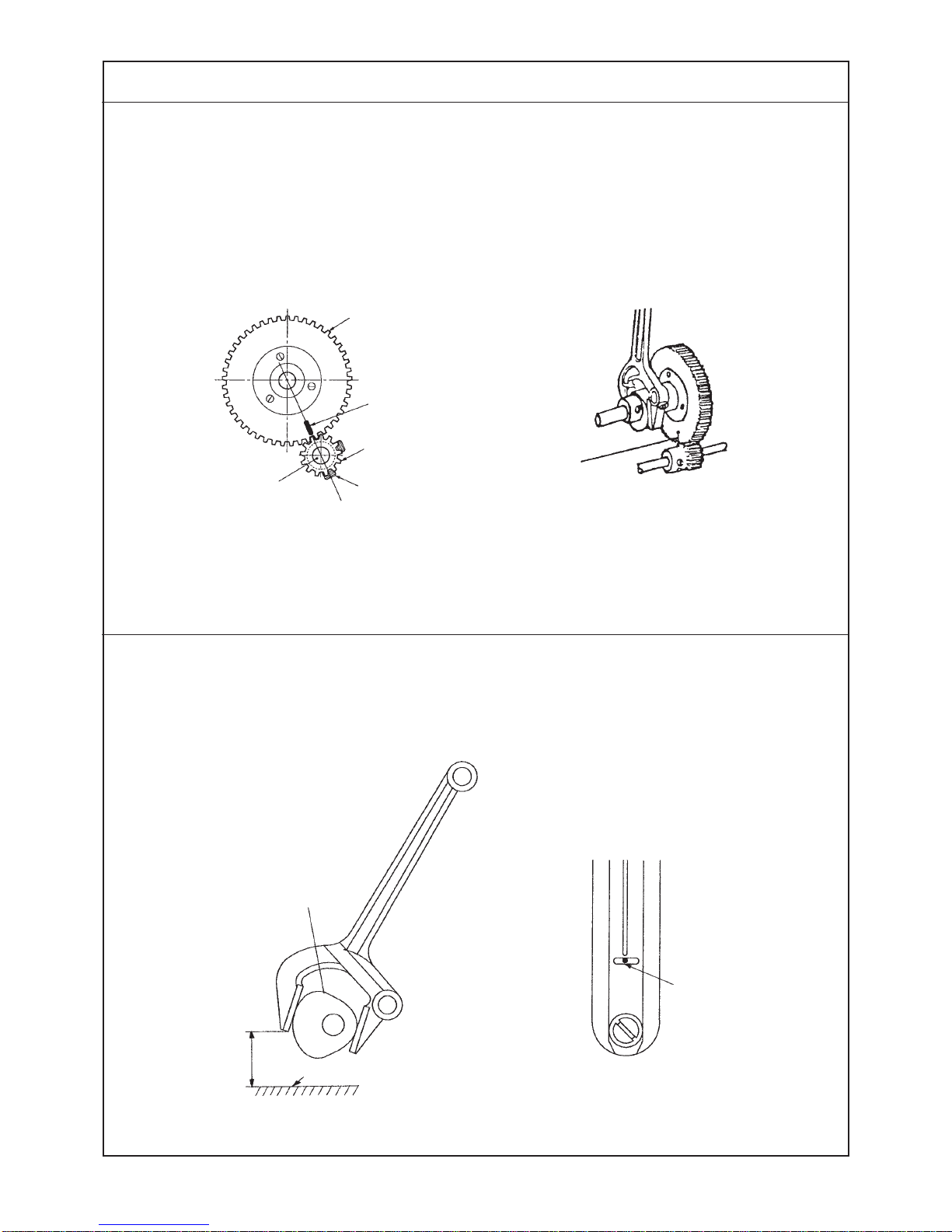
(1) Height of the needle bar ................................................................................................. 2
(2) Needle-to-hook timing .................................................................................................... 2
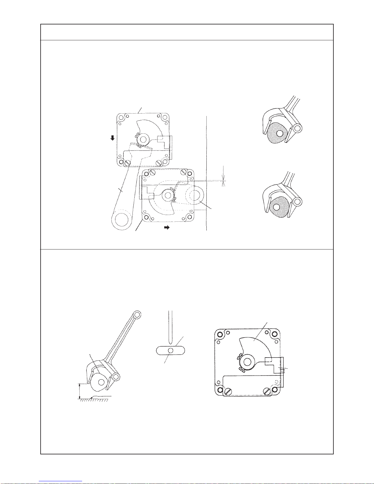
(3) Needle rocking timing..................................................................................................... 4
(4) Height of the needle bar rocking rod (adjusting the reference of needle bar
rocking components)...................................................................................................... 4
(5) Adjusting the stitch width PM arm and backlashes of the stitch base line
and stitch width gears ....................................................................................................6
(6) Detecting the origin of the stitch base line stepping motor ....................................... 6
(7) Detecting the origin of the stitch width stepping motor ............................................. 8
(8) Backlash of the feed gear............................................................................................... 8
(9) Longitudinal position of the presser and the feed shaft ........................................... 10
(10) Knife drop position...................................................................................................... 10
(11) Knife bar/position of the knife installing base/knife bar stroke .............................. 12
(12) Knife detector sensor.................................................................................................. 14
(13) Position of the starting safety arm............................................................................. 16
(14) Adjusting the starting safety hook............................................................................. 16
(15) Adjusting the starting sensor..................................................................................... 18
(16) Adjusting the needle thread trimmer control lever .................................................. 20
(17) Adjusting the stop-motion solenoid .......................................................................... 20
(18) Stroke of the stop-motion solenoid ........................................................................... 22
(19) Longitudinal amount of the needle thread trimmer.................................................. 22
(20) Lateral position of the needle thread trimmer .......................................................... 24
(21) Height of the needle thread trimmer.......................................................................... 24
(22) Position of winding the needle thread at the start of sewing.................................. 26
(23) Opening timing of the needle thread trimmer........................................................... 26
(24) Spring pressure of the needle thread trimmer.......................................................... 28
(25) Adjusting the needle thread trimmer lever................................................................ 28
(26) Position of the bobbin thread trimmer/position of bobbin thread clamp plate ..... 30
(27) Timing to open the bobbin thread trimmer and the opening amount / adjusting
the bobbin winder trip latch........................................................................................ 30
(28) Height of the presser................................................................................................... 32
(29) Adjusting the thread tension solenoid ...................................................................... 32
(30) Adjusting the safety switch ........................................................................................ 34
(31) Adjusting the bobbin winder ...................................................................................... 34
(32) Adjusting the thread breakage detecting plate......................................................... 36
(33) Adjusting the presser lifting solenoid ....................................................................... 36
(34) Adjusting the presser lifting air cylinder................................................................... 38
(35) Adjusting the presser fall detecting plate ................................................................. 38
3. DISASSEMBLING/ASSEMBLING PROCEDURE .......................................... 40
(1) Disassembling/assembling the hook driving shaft.................................................... 40
(2) Disassembling/assembling the main shaft ................................................................. 42
(3) Adjusting the timing belt tension................................................................................. 44

4. ADJUSTMENT OF THE ORIGIN SENSOR .................................................... 46
(1) Adjusting procedure of the upper detecting plate ..................................................... 46
(2) Adjusting procedure of stepping motor origin........................................................... 47
5. LUBRICATION MECHANISM .........................................................................49
(1) Lubrication ..................................................................................................................... 49
(2) Lubricating the respective components...................................................................... 49
(3) Adjusting the amount of oil .......................................................................................... 50
(4) Lubricating other components..................................................................................... 50
6. DESCRIPTION OF OPERATION PANEL ....................................................... 52
(1) Sewing data.................................................................................................................... 54
(2) Sewing data list.............................................................................................................. 54
(3) Making the radial flow bar-tacking shape ................................................................... 58
(4) Sewing data initial value table...................................................................................... 59
(5) Sewing data initial value table (Change not possible)............................................... 60
7. MEMORY SWITCH.......................................................................................... 61
(1) How to use the memory switch.................................................................................... 61
(2) Memory switch list......................................................................................................... 62
(3) How to set the memory switch..................................................................................... 63
(4) DIP switches on the SDC circuit board ....................................................................... 72
8. TEST MODE ....................................................................................................73
(1) How to use the test mode ............................................................................................. 73
9. ERROR DISPLAY LIST................................................................................... 74
10. TROUBLES AND CORRECTIVE MEASURES............................................. 80
(1) With regard to sewing ................................................................................................... 80
(2) Woth regard to mechanical components .................................................................... 89
(3) With regard to electrical components ......................................................................... 92
11. CIRCUIT DIAGRAM .................................................................................... 104
12. OPTIONAL PARTS ..................................................................................... 116
(1) Table of the optional parts.......................................................................................... 116
(2) Thread tension VR (variable resistor)........................................................................ 116
13. OTHERS ...................................................................................................... 117
(1) How to remodel the presser to the type 4 presser ................................................... 117
(2) Points of replacing the presser with that of 60 mm or 70 mm ................................ 118
14. DRAWING OF THE TABLE ........................................................................ 121

−1−
1. SPECIFICATIONS
Model
Stitch width (max.)
Length of buttonhole
(length of knife)
Stitch length (max.)
1 Sewing speed
2 Needle
3 Needle bar stroke
4 Thread take-up lever
5 Hook
6 Lift of work clamp check
7 Bobbin winder
8 Feed drive method
9 Dimensions
10 Weight of machine head
11
Adjustment of needle thread
12
Data that can be stored in memory
13 Bar-tacking shape
14
Change-over of 1/2 stitching
15
Input voltage classification
16 Motor
17 Lubrication method
18 Lubricating oil
When presser type 1 is used
4 mm
6.4 to 19.1 mm
(1/4" to 3/4")
25 mm
When presser type 3 is used
5 mm
6.4 to 31.8 mm
(1/4" to 1-1/4")
41 mm
LBH-1700 LBH-1702
5 mm
6.4 to 25.4 mm
(1/4" to 1")
35 mm
Standard 3,000 rpm (Number of revolution can be controlled.) Max. 3,600 rpm
DP X 5J (SCHMETZ 134R)
34.6 mm
Link thread take-up lever
DP type full-rotary automatic lubricating hook
12 mm
Built-in machine head type
Drive by stepping motor, rack and pinion
Width of machine bed : 185 mm
Height (from table top surface to top end of top cover) : 364 mm
Length (from front end of machine bed to rear end of motor cover) : 630 mm
50 kg
Active tension method
Digital setting for each section by means of operation panel (Parallel section tension,
bar-tacking section tension)
Max. 89 patterns
Square shape, radial shape, round shape (selection by operation panel)
Radial taper bar, Radial straight bar
Each pattern can be set.
Domestic : 1ø 100V/ 3ø 200V
Export : 1ø 100 to 240V 1ø 220 to 415V
3ø 200 to 240V 3ø 220 to 415V
Compact AC servo motor 450W
Direct-drive method
Automatic lubrication method
JUKI New Defrix oil No.1 (Equivalent to ISO VG7)
When presser type 2 is used
5 mm
6.4 to 25.4 mm
(1/4" to 1")
35 mm

−2−
Standard Adjustment
Needle
1.6 to 1.8 mm 0.01 to 0.04 mm
0 to 0.02 mm
2. STANDARD ADJUSTMENT
(1) Height of the needle bar
Adjust the height of the needle bar so that the distance from the top surface of the throat plate to the lower
end face of the needle bar is 11.9 mm (standard) or 11.4 mm (K) when the needle bar is in the lowest dead
point.
(2) Needle-to-hook timing
1) Blade point of the hook is aligned with the center of the needle when the needle bar goes up by 2.3 mm
(standard) or by 2.8 mm (K) from its lowest dead point.
At this time, the distance from the top end of the needle eyelet to the blade point of the hook is 1.6 to 1.8
mm (needle is in the central section of the hole in the throat plate).
2) The clearance provided between the needle and the blade point of the hook is 0.01 to 0.04 mm (needle
is rocked to the right of the hole in the throat plate).
3) Adjustment value of the needle guard is 0 to 0.02 mm (needle is in the central section of the hole in the
throat plate).
Blade point
of hook
Setscrew in the needle
bar connection
Needle guard
1

−3−
Adjustment Procedures Results of Improper Adjustment
0 to 0.2 mm
1. Enter timing gauge 1supplied with the machine as
accessories between the throat plate and the lower end of
the needle bar as shown in the figure, loosen the setscrew in
the needle bar connection, and adjust the height of the needle
bar.
(Caution) Adjust the height of the needle bar when the
needle is positioned in the center of the needle
hole in the throat plate.
2. Table of timing gauge
Part No. of timing gauge : B9101771000 (Standard)
D9101771K00 (K)
1. Make a state that the needle is in the center of the hole in the
throat plate and the needle bar starts going up from the lowest
dead point. Then, enter the timing gauge 2 between the throat
plate and the lower end of the needle bar as shown in the
figure and loosen the hook sleeve setscrew to adjust the
timing.
2. The clearance provided between the needle and the blade
point of the hook is 0.01 to 0.04 mm when the needle is rocked
to the right of the hole in the throat plate.
3. In this state, adjust the relation of the position of the inner
hook and the bobbin case positioning stopper to 0 to 0.2 mm
as shown in the figure below. Then, securely tighten with the
stopper setscrew.
Bobbin case positioning
stopper
Sub-class
type Timing gauge
12
Standard 11.9 mm 14.2 mm
K 11.4 mm 14.2 mm
Inner hook
™For the floppy fabrics, it is effective
when the needle bar is slightly
lowered than the standard value.
™For the floppy fabrics, it is effective
when the hook timing is slightly
retarded than the standard value.
(Clrarance provided between the
upper end of the needle eyelet and
the blade point of the hook is
desired to be approximately 1.0
mm.)
™For the purl stitching, if the hook
timing is advanced, crest of seam
is likely to be improved. On the
contrary, if the hook timing is
retarded, stitch skipping is
improved, but crest of seam is likely
to be slightly deteriorated.

−4−
Standard Adjustment
(3) Needle rocking timing
The engraved marker line on the needle rocking drive large gear is aligned with the center of the hook
driving shaft when the needle bar has reached its highest point (needle should complete rocking when the
needle comes down and passes the throat plate).
(4) Height of the needle bar rocking rod (adjusting the reference of needle bar rocking
components)
Needle bar rocking cam is located on the stitch base line side and the needle enters in the center of the hole
in the throat plate when the clearance provided between the lower end of the needle bar rocking rod and the
machine bed is 8 mm.
Needle rocking
drive large gear
Needle bar rocking cam
Engraved
marker line
Hook driving
shaft
Needle rocking
drive pinion
Setscrew No. 1
Engraved
marker line
Top surface of machine bed
(Figure observed from the front side of the sewing machine)
Needle entry
8 mm

−5−
Adjustment Procedures Results of Improper Adjustment
1. Adjust the timing by the needle rocking drive pinion.
<How to check after the adjustment>
Place a sheet of paper at the needle entry position, turn the
hand pulley by hand and make sure that the needle sways in
the lateral direction.
Place a block of 8 mm under the rod and press down the needle
bar rocking rod. Then, the rod comes down. In this state, loosen
the setscrew in the needle bar rocking arm, rear to adjust the
height.
(Caution) When tightening the setscrew in the needle bar
rocking arm, rear, tighten it so that there is no
thrust play between the needle bar rocking arm,
rear and the needle bar rocking shaft bushing.
Setscrew Needle bar rocking
arm, rear
Needle bar rocking rod
™When the engraved marker line is
not aligned, needle sways to cause
needle breakage, stitch skipping,
etc.
™When the height of the needle bar
rocking rod is improper, stitch width
of parallel section of the right and
left sides will change.
™If the needle entry position is
improper, when the needle stitch
width is increased, the other side
comes in contact with the needle
and the hole in the throat plate. As
a result, needle breakage or thread
breakage will result.

−6−
Standard Adjustment
8 mm
Needle
(5) Adjusting the stitch width PM arm and backlashes of the stitch base line and stitch
width gears
a) When the stitch width is “0” mm, the clearance provided between the frame and the stitch width PM arm
is 1 mm.
b) Stitch base line and stitch width stepping motor gears should run smoothly without backlashes.
(6) Detecting the origin of the stitch base line stepping motor
When the needle enters in the center of the needle hole in the throat plate, the stitch base line origin sensor
should detect the origin detecting plate.
(Caution) The stitch base line stepping motor is the one with white connector. (Upper side)
Stitch base line stepping motor
Needle bar
rocking cam
Condition :
The needle bar should
be in the lower dead
point of its stroke.
Condition :
The needle bar rocking cam
should be on the stitch base
line side.
Stitch base
line PM arm
Stitch width stepping motor
Stitch width
PM arm
Needle bar rocking cam is
on the stitch base line side.
Needle bar rocking cam is
on the stitch width side.
Top surface of machine bed
(Figure observed from the front side of the sewing machine)
Needle
hole
Origin detecting plate
Stitch base line
origin sensor
1 mm

−7−
Adjustment Procedures Results of Improper Adjustment
a) 1. Turn the hand pulley to bring the needle bar rocking cam to
the stitch base line side, and confirm the “0” position (center
of the needle hole) of the stitch base line.
2. Further, turn the hand pulley to bring the needle bar rocking
cam to the stitch width side, and set the needle bar to the
lower dead point of its stroke.
3. Move the needle bar to the right or left to set the needle at
the center of the needle hole.
4. Provide a clearance of 1 mm between the stitch width PM
arm and the frame, and tighten with the setscrews in the stitch
width adjusting arm.
b) Loosen respective setscrews in the respective stepping motors,
lightly preess the motors in the direction of a, and adjust the
backlashes of the gears.
™Loosen the setscrews in the origin detecting plate to adjust
the plate.
How to check
• Pressing the right key, turn ON the power to set the test
mode.
(Refer to page 73.)
• Select No. 1 with the left or key. (Input check)
• Detection of the sensor can be checked by turning ON or
OFF of the second LED from the left of the right 4-digit LED.
(1, 0)
™Origin compensation procedure by means of the panel (Refer
to page 47.)
Pressing the key, right, turn ON the power. Compensate
the needle position with the origin compensation mode No.
52.
Setscrews in stitch
width adjusting arm
™If the clearance is smaller than the
specified value, when
compensating the stitch width
amount, the stitch width PM arm
comes in contact with the frame.
™If the clearance is larger than the
specified value, when retrieving the
origin, Er 43 occurs. Or, when the
stitch width is maximum, the stitch
width PM arm comes in contact with
the frame. As a result, the stitch
width may not be obtained.
™If the backlash of stepping motor
gear is large, needle entry accuracy
will be deteriorated.
™If there is no backlash between the
stepping motor gears and the gears
are excessively pressed, motor
torque will occur.
™When the needle is located on the
right side from the center of the
needle hole, it will cut the stitches.
When it is on the left side, the
presser may come in contact with
the needle.

−8−
Standard Adjustment
(7) Detecting the origin of the stitch width stepping motor
When the needle bar rocking cam is located on the stitch base line side and the needle enters in the center
of the needle hole in the throat plate (when stitch width amount is “0” mm), the stitch width origin sensor
should detect the origin detecting plate.
(Caution) The stitch width stepping motor is the one with blue connector. (Lower side)
Perform the adjustment when the stitch base line origin sensor is in the origin.
(8) Backlash of the feed gear
Backlash : 0 to 0.05 mm
Stitch width
origin sensor
Feed gear
Origin detecting plate
Feed stepping motor
Setscrews Feed shaft
Small
↑
Backlash
↓
Large

−9−
Adjustment Procedures Results of Improper Adjustment
™Loosen the setscrews in the origin detecting plate to adjudst
the plate.
How to check
• Pressing the right key, turn ON the power to set the test
mode. (Refer to page 73.)
• Select No. 1 with the left or key (input check).
• Detection of the sensor can be checked by turning ON or
OFF of the third LED from the left of the right 4-digit LED.
™Origin compensation procedure by means of the panel (Refer
to page 47.)
Pressing the right key, turn ON the power. Compensate
the needle position with the origin compensating mode No.
53.
1. Loosen the setscrews in the feed base.
(To protect the gear sections of the feed gear and feed shaft
gear from the end tooth bearing)
2. Loosen four setscrews in the feed stepping motor and move
the feed stepping motor up or down in the direction of the
arrow to adjust the backlash.
3. Tighten the setscrews in the feed base so that the end tooth
bearing of the gear sections of the feed gear and the feed
shaft gear does not occur.
(Caution) After the assembling, move the work clamp back
and forth by hand to check whether there is any
uneven trorque.
Feed shaft
Feed base
Setscrews
™When the needle is on the right side
from the center of the needle hole,
stitches are increased and the
presser comes in contact with the
needle. Or, stitches may be cut.
When it is on the left side, stitch
width is decreased.
™If the backlash is large, feed pitch
shift will occur. Or, if it is too small,
defective feed (step-out of stepping
motor) will occur.

−10 −
Standard Adjustment
5 mm
(9) Longitudinal position of the presser and the feed shaft
™Distance from the center of the needle hole in the throat plate to the end face of the presser is 2.5 ±0.3
mm (when the feed origin is detected).
™When the feed origin is detected, the distance from the top end of the feed shaft to the end face of the
feed shaft bushing is 5 mm.
(10) Knife drop position
Knife should drop in the center of the knife drop groove in the throat plate.
Knife drop groove
Feed shaft
Feed shaft bushing
Setscrews
Sensor installing
plate setscrews
Sensor installing
plate
Feed base
Throat plate
2.5 ±0.3 mm
(2.2 to 2.8 mm)
Presser

−11 −
Adjustment Procedures Results of Improper Adjustment
1. Tighten the setscrews so that the distance from the presser to
the needle hole is 2.5 mm and so that the feed shaft protrudes
by 5 mm from the feed shaft bushing.
(Caution) When tightening the setscrews, turn the feed shaft
and tighten the setscrews in the center of the
backlash in the rotating direction so that the feed
stepping motor gear and the feed shaft gear do
not produce the end tooth bearing.
2. When the feed origin is detected, adjust the distance from
the presser to the needle hole to 2.5 ±0.3 mm, and fix the
position of the sensor installing plate with the sensor installing
plate setscrews.
™How to check
• Pressing the right key, turn ON the power to set the test
mode. (Refer to page 73.)
• Select No. 1 with the left or key. (Input check)
• Detection of the sensor can be checked by turning ON or
OFF of the leftmost LED of the right 4-digit LED.
™Origin compensation procedure by means of the panel (Refer
to page 47.)
• Pressing the right key, turn ON the power. Compensate
the feed position with the origin compensation mode No. 51
Adjust the position at the installing position of the throat plate
base.
Throat plate
Throat plate base
™If the position of the presser is
improper (longitudinal position of
the work clamp is also improper),
opening/closing of the needle
thread trimmer will be affected.
™When the feed origin is detected, if
the distance from the needle hole
to the presser is excessively narrow,
the presser comes in contact with
theneedleattheoverlappedsection
resulting in thread breakage or
needle breakage.
™Improper position of the feed shaft
is related to the maladjustment of
the bobbin thread trimmer driving
cam resulting in defective bobbin
thread winding.

−12 −
Standard Adjustment
0 to 1 mm
0.4 to 0.6 mm
4 to 5 mm
(11) Knife bar/position of the knife installing base/knife bar stroke
a) Clearance provided between the cloth cutting knife and the needle bar is 0.4 to 0.6 mm.
b) When the knife bar is at the stop position, the distance from the jaw section of the machine arm to the top
end of the concave of the knife bar is 0 to 1 mm.
c) For the solenoid type, the distance from the top surface of the machine arm to the top end of the knife bar
is 4 to 5 mm when lightly pressing down the knife bar by hand.
Knife bar
Needle bar
Concave of knife bar
Knife installing base setscrews
Knife installing base
Cloth cutting knife
Solenoid setscrews Knife driving lever
To lightly press by hand
Knife driving solenoid Solenoid setscrews
Knife driving
lever stopper
Stopper nut
Cylinder setscrews
Knife driving cylinder
Cylinder setscrews

−13 −
Adjustment Procedures Results of Improper Adjustment
a) Lower the needle bar, loosen the knife installing base
setscrews, and move the knife installing base to the right or
left to adjust the clearance.
b) For the solenoid type, loosen the stopper nut and adjust the
position of the knife driving lever stopper.
™For the air cylinder type, loosen the cylinder setscrews and
adjust the position of the knife driving cylinder.
(Caution) For the air cylinder type, when the cylinder is
positioned on the way, the adjustment becomes
improper. Perform the adjustment with the air
connected.
c) Loosen the solenoid setscrews and adjust the position of the
knife driving solenoid.
™If the distance from the cloth cutting
knife to the needle bar is smaller
than the specified value, the knife
comes in contact with the needle
bar. As a result, noise will occur, the
knife will wear out, or cloth will be
stained.
™If the distance from the cloth cutting
knife to the needle bar is larger than
the specified value, the distance
from the front bar-tacking and the
knife hole is increased and the rear
bar-tacking may be cut.
™If the distance is excessively small,
the knife installing base comes in
contact with the jaw section of the
machine arm and a big noise
occurs.
™If the distance is excessively large,
the knife may come out under the
presser when the presser is lifted.
™If the distance is large, cloth may
not be cut.
™If the distance is small, the knife
driving lever may come in contact
with the machine arm.

−14 −
Standard Adjustment
1Screws 2Screw
3Knife detector
sensor
installing base
4Origin
detecting plate
5Pin
6Knife detector sensor
(12) Knife detector sensor

−15 −
Adjustment Procedures Results of Improper Adjustment
Adjust and fix knife detector sensor installing base 3and origin
detecting plate 4with screws 1and 2so that the detecting
plate enters upper/lower, right/left and center sections of the
sensor detecting section when the knife bar returns to the upper
side.
Caution : When the knife bar returns to the upper side, turn
pin 5and make sure that it does not come in
contact with knife detector sensor 6.

−16 −
Standard Adjustment
0.3 to 0.8 mm
0.5 ±0.2 mm
(13) Position of the starting safety arm
Clearance provided between the starting safety arm and the presser bar lever is 0.3 to 0.8 mm.
(14) Adjusting the starting safety hook
Starting safety hook
Starting sensor plate
Stopper
Nut
Starting sensor
Starting safety lever
Starting lever
Stopper screw
Starting safety hook
Nut
Other manuals for LBH-1700
1
Table of contents
Other JUKI Sewing Machine manuals

JUKI
JUKI MO-623 User manual

JUKI
JUKI LBH-1796A User manual

JUKI
JUKI MO-2800 User manual

JUKI
JUKI HZL-355ZW-A User manual

JUKI
JUKI AMS-224EN/IP-420 User manual

JUKI
JUKI MO-6704D User manual

JUKI
JUKI AMB-289/IP-420 User manual

JUKI
JUKI HZL-12Z User manual

JUKI
JUKI IP-100 User manual

JUKI
JUKI LU-2810 Series User manual

JUKI
JUKI TL-2010Q User manual

JUKI
JUKI LZ-2290A-SR-7 User manual

JUKI
JUKI MEB-3200 Series Quick start guide

JUKI
JUKI Exceed F-300 Installation guide

JUKI
JUKI AW-3SD User manual

JUKI
JUKI LH-3126F Installation guide

JUKI
JUKI LU-1520N-7 User manual

JUKI
JUKI DLN-5410N User manual

JUKI
JUKI MCS-1500 User manual

JUKI
JUKI LU-1510 User manual