JUKI J-350QVP User manual

Lockstitch machine with a long arm and a thread trimmer
INSTRUCTION MANUAL
J-350QVP
Attention :
Congratulations on your purchase of a JUKI sewing machine.
Please be sure to read this Instruction Manual before operating the sewing machine
to ensure safe operation. Please be sure to keep the Instruction Manual so that you
can read it whenever necessary.
JUKI website: http://www.juki.com
EN

– 1 –
"IMPORTANT SAFETY INSTRUCTIONS"
When using an electrical appliance, basic safety precautions should always be followed, including the
following: Read all instructions before using this sewing machine.
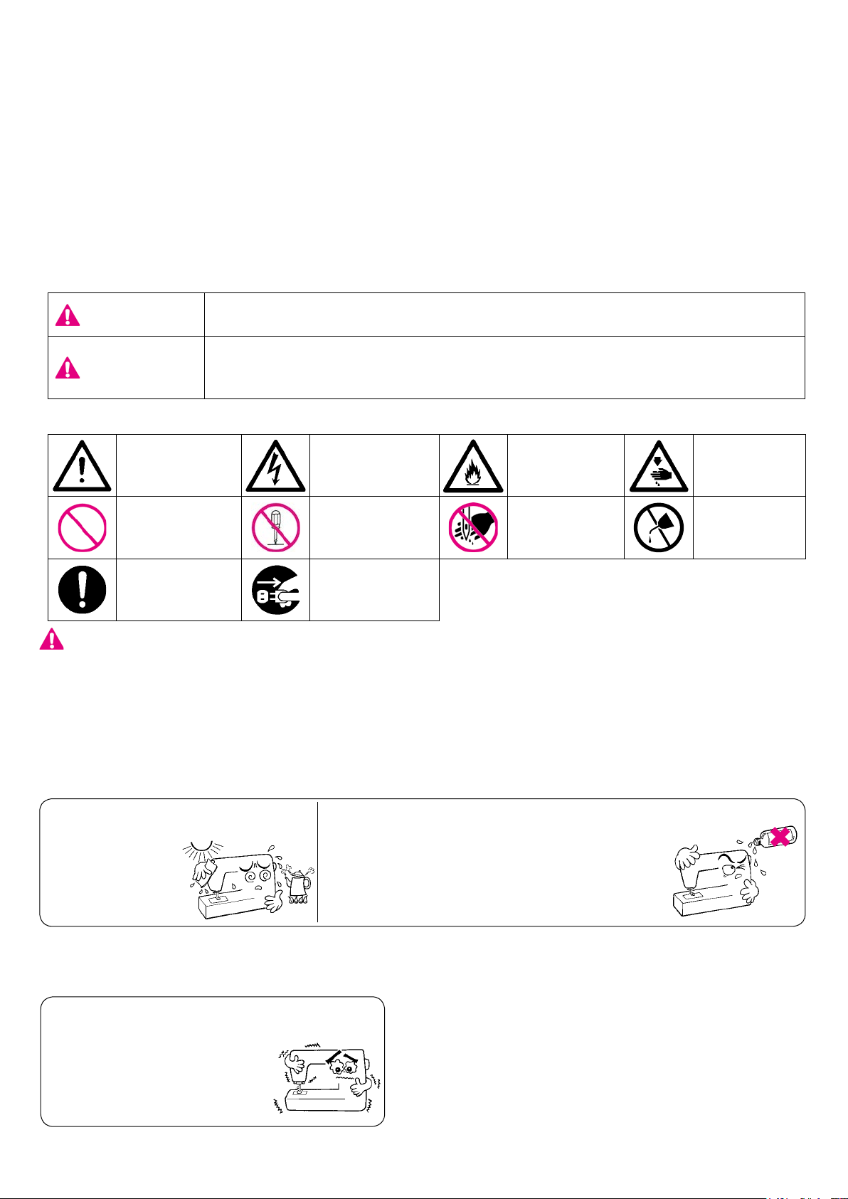
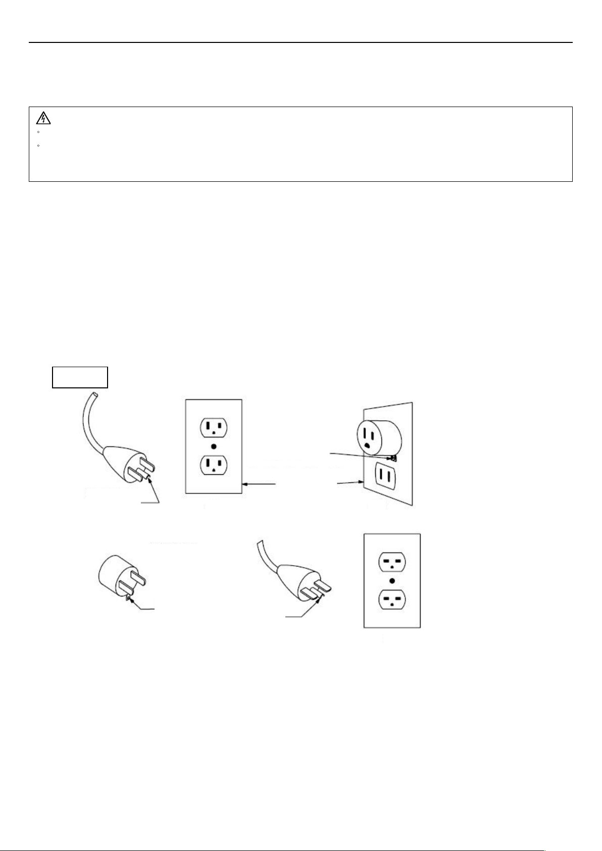
"DANGER ____ To reduce the risk of electric shock:"
1. An appliance should never be left unattended when plugged in.
2. Always unplug this appliance from the electric outlet immediately after using and before cleaning.
"WARNING ____ To reduce the risk of burns, re, electric shock, or injury to persons:"
1. Do not allow this appliance to be used as a toy. Close attention is necessary when this appliance
is used by or near children. This appliance can be used by children aged from 8 years and above
and persons with reduced physical, sensory or mental capabilities or lack of experience and
knowledge if they have been given supervision or instruction concerning use of the appliance
in a safe way and understand the hazards involved. Children shall not play with the appliance.
Cleaning and user maintenance shall not be made by children without supervision.
2. Use this appliance only for its intended use as described in this manual. Use only attachments
recommended by the manufacturer as contained in this manual.
3. Never operate this appliance if it has a damaged cord or plug, if it is not working properly, if it has
been dropped or damaged, or dropped into water. Return the appliance to the nearest authorized
dealer or service center for examination, repair, electrical or mechanical adjustment.
4. Never operate the appliance with any air openings blocked. Keep ventilation openings of the sew-
ing machine and foot controller free from the accumulation of lint, dust and loose cloth.
5. Keep ngers away from all moving parts. Special care is required around the sewing machine
needle.
6. Always use the proper throat plate. The wrong plate can cause the needle to break.
7. Do not use bent needles.
8. Do not pull or push fabric while stitching. It may deect the needle causing it to break.
9. Switch the sewing machine off ("O") when making any adjustments in the needle area, such as
threading needle, changing needle, threading bobbin, or changing presser foot and the like.
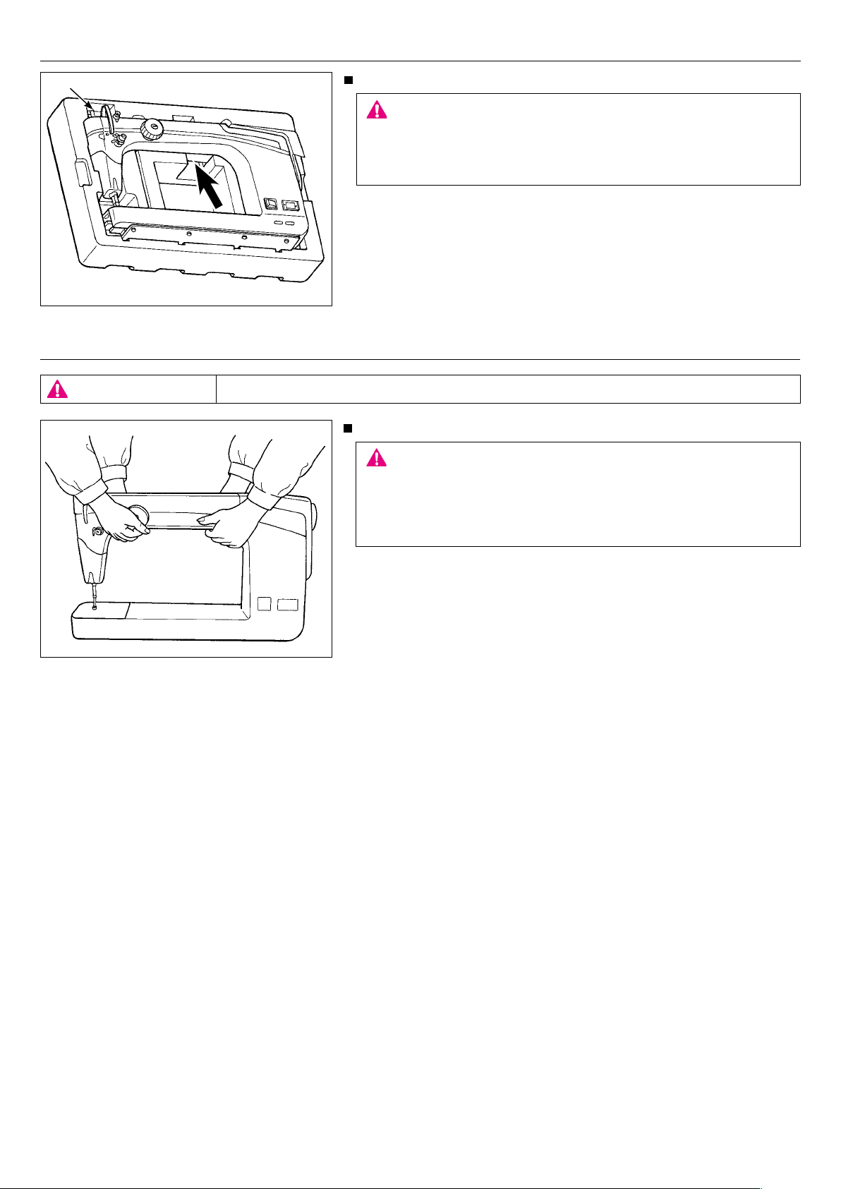
10. Always unplug sewing machine from the electrical outlet when removing covers, lubricating, or
when making any other user servicing adjustments mentioned in the instruction manual.
11. Never drop or insert any object into any opening.
12. Do not use outdoors.
13. Do not operate where aerosol (spray) products are being used or where oxygen is being adminis-
tered.
14. To disconnect, turn all controls to the off ("0") position, then remove plug from outlet.
15. Do not unplug by pulling on cord. To unplug, grasp the plug, not the cord.
16. Turn OFF the power switch before insertion/removal of any cords and any plugs.
17. Basically, the machine should be disconnected from the electricity supply when not in use.
18. If the power cord of this appliance is damaged, it must be replaced with a special cord byyour
nearest authorized dealer or service center.
"SAVE THESE INSTRUCTIONS"
This sewing machine is intended for household use only.
Use the stitch regulator made by the Grace Company.
Stitch regulator can be used on the following machine model-number.
In order to use your machine safely, be sure to read the Instruction Manual for the Sure Stitch for
JUKI J-350QVP provided by Grace Company for how to install the machine on the frame, how to con-
nect the stitch regulator and how to operate the machine.
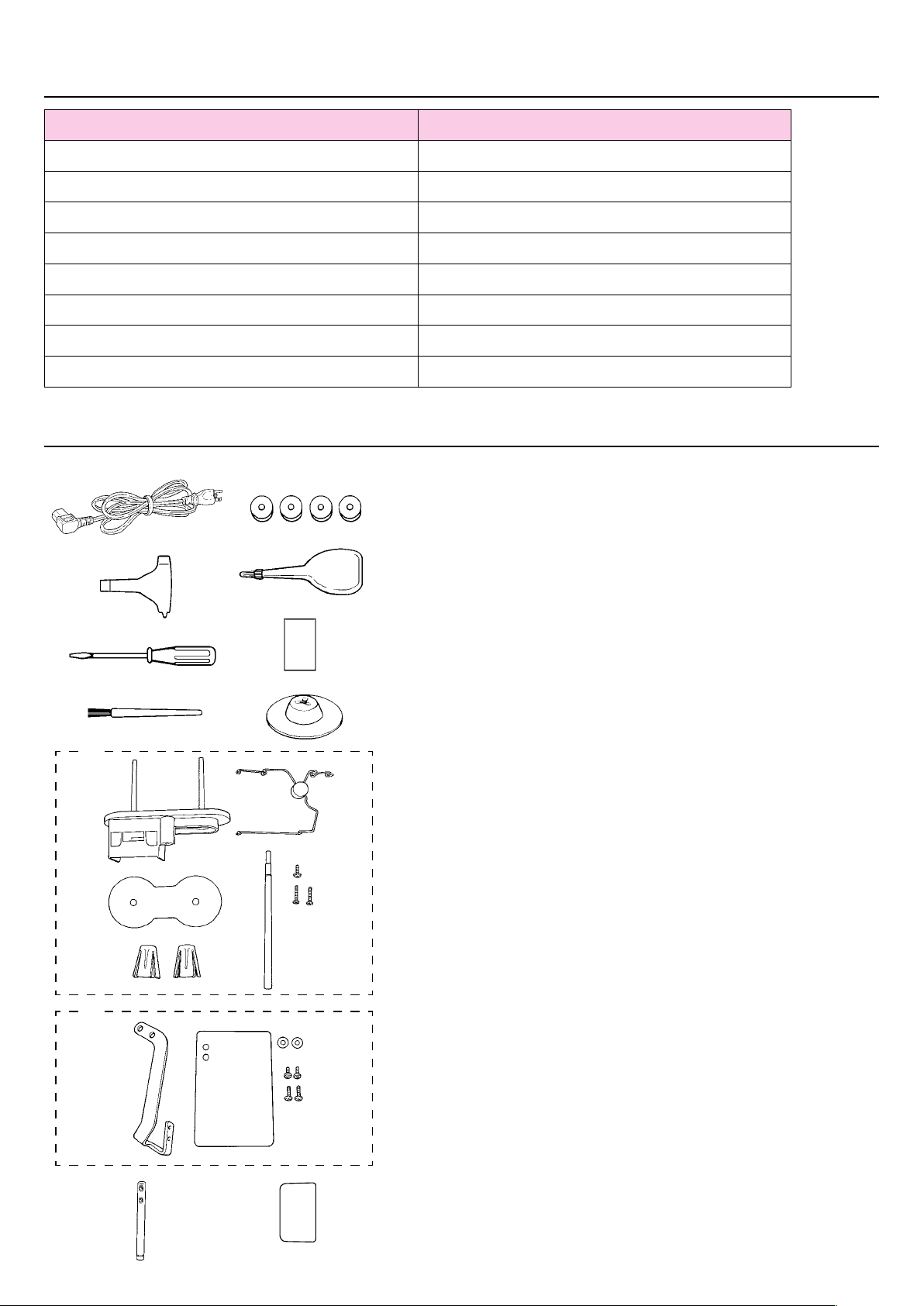
Sewing machine model number Stitch regulator model number
J-350QVP Sure Stitch for JUKI J-350

– 2 –
Danger
warning which
is not specied
There is a risk
of electrical
shock
There is a risk
of re
There is a
risk of injury
to hands, etc.
Prohibited
matter which is
not specied
Disassembly/
alteration is
prohibited
Do not place
ngers under
the needle
Do not pour
oil, etc.
Generally
required
behavior
Disconnect the
power plug
Congratulations on your purchase of a JUKI sewing machine.
Please be sure to read safety precautions in "To use the sewing machine safely" in the Instruction
Manual before use to fully understand the functions and operating procedures of the sewing ma-
chine so as to use the sewing machine for a long time.
After you have read the Instruction Manual, please be sure to keep it together with the warranty so
that you can read it whenever necessary.
To use the sewing machine safely
Marks and pictographs included in the Instruction Manual and shown on the sewing machine are
used so as to ensure safe operation of the sewing machine and to prevent possible risk of injury to
the user and other people.
Warning marks are used for different purposes as described below.
WARNING Indicates that there is a possible risk of death or serious injury if this
mark is ignored and the sewing machine is used in a wrong manner.
ATTENTION
Indicates the operation, etc. which can cause a possible risk of personal
injury and/or physical damage if this mark is ignored and the sewing ma-
chine is used in a wrong manner.
Pictographs mean the following:
* The operating temperature of the sewing machine
is between 5ºC and 40ºC. Do not use the sewing
machine under the direct sunlight, near the burning
things such as a stove and candle, or in a humid
place. By so doing, the temperature in the interior
portion of the sewing machine can rise or the coat-
ing of the power cord can melt, causing re or elec-
trical shock.
●
Do not wipe the sewing machine with solvent such as thinner.
When the sewing machine is soiled, put
a small quantity of neutral detergent on a
piece of soft cloth and carefully wipe off the
sewing machine with it.
● Be sure to use the sewing machine in
the temperature range
from 5ºC to 40ºC.
If the temperature is exces-
sively low, the machine can
fail to operate normally.
WARNING
For the combination of the material and the thread and needle, in particular, refer to the explanation
table in "Replacement of the needle".
If the needle or thread does not match the material used such as in the case that an extra heavy-
weight material (e.g., denim) is sewn with a thin needle (#11 or higher), the needle can break re-
sulting in an unexpected personal injury.
Other precautions
● Do not put the sewing machine
under the direct
sunlight or
in ahumid
place.
Be aware that the following state can take place since the sewing machine incorporates semi-con-
ductor electronic parts and precise electronic circuits.

– 3 –
How to hold the sewing machine
Carry the sewing machine while holding the machine arm with two per-
sons as shown in the gure.
CAUTION
1. Never hold the handwheel since it rotates.
2. Always must be handle the sewing machine with two persons or
more since the sewing machine weighs 26 kg or more.
3. Do not hold the sewing machine by placing hands near the needle
bar and the presser bar to avoid the risk of injury.
HOW TO CARRY THE SEWING MACHINE
How to take out the sewing machine
Pull out the sewing machine from the cutout of styrene foam by holding
the main body of the arm.
CAUTION
If you pull up the sewing machine by holding presser regulating screw
section A, the sewing machine can break.
In addition, be aware that the presser regulating screw can break if a
physical impact is given to it.
A
CAUTION Turn OFF the power switch. Always must be disconnected plug from socket-outlet.

– 4 –
GROUNDING INSTRUCTIONS
This product must be grounded. In the event of malfunction or breakdown, grounding provides a path of least resistance
for electric current to reduce the risk of electric shock. This product is equipped with a cord having an equipment-ground-
ing conductor and a grounding plug. The plug must be plugged into an appropriate outlet that is properly installed and
grounded in accordance with all local codes and ordinances.
Check with a qualied electrician or serviceman if the grounding instructions are not completely understood, or if in doubt
as to whether the product is properly grounded.
Do not modify the plug provided with the product. if it will not t the outlet, have a proper outlet installed by a qualied
electrician.
This product is for use on a nominal 120 V circuit, and has a grounding plug that looks like the plug illustrated in sketch
Ain Figure 1. A temporary adaptor, which looks like the adaptor illustrated in sketches Band C, may be used to connect
this plug to a 2-pole receptacle as shown in sketch Bif a properly grounded outlet is not available. The temporary adaptor
should be used only until a properly grounded outlet can be installed by a qualied electrician. The green colored rigid ear,
lug, and the like, extending from the adaptor must be connected to a permanent ground such as a properly grounded out-
let box cover. Whenever the adaptor is used, it must be held in place by the metal screw.
Grounding
pin
Adapter
(A)
(C)
(B)
(D)
Grounding
means Grounding
pin
Metal
screw
Cover of
grounded
outlet box
Figure 1
DANGER
・
Improper connection of the equipment-grounding conductor can result in a risk of electric shock.
・
The conductor with insulation having an outer surface that is green with or without yellow stripes is the equipment-
grounding conductor. If repair or replacement of the cord or plug is necessary, do not connect the equipment-grounding
conductor to a live terminal.

– 5 –
CONTENTS
IMPORTANT SAFETY INSTRUCTIONS...................................................1-2
HOW TO CARRY THE SEWING MACHINE ...............................................3
GROUNDING INSTRUCTIONS ...................................................................4
Specications ...............................................................................................6
Accessories ..................................................................................................6
Principal Parts ..............................................................................................7
Name and Function of each component..................................................8-12
Winding the bobbin................................................................................13-16
Attaching the needle...................................................................................16
Threading the machine...............................................................................17
Adjusting the thread tension..................................................................18-19
Presser foot lifting lever.............................................................................. 19
Setup and operation ..............................................................................20-27
Maintenance............................................................................................... 28
Maintenance and lubrication..................................................................28-29
Troubles and Corrective Measures ............................................................30

– 6 –
Accessories
1. Power cord
2. Exclusive screwdriver
3. Screwdriver (medium)
4. Cleaning brush
5. Bobbins (4pcs.)
6. Oilcan
7. Needles (GB 134R #18)
8. Spool cap
9. Thread stand components
(Spool holder disk, thread stand thread guide, bobbin winderspool
holder disk, bobbin winder seat, bobbin winder side anchors(two
pieces), setscrew (large), setscrews (small) (two pieces))
10. Eye protection cover components
(Safety plate, safety plate mounting plate, washers (two
pieces),setscrews (large) (two pieces), setscrews (small) (two
pieces))
11. Thread guide pin
12. Blind seal (Spare)
1
2
3
4
5
6
7
8
11 12
9
10
Specications
Description Specication
Sewing speed Max. 2,200 sti/min
Needle bar stroke 35 mm
Lift of presser foot 4.5 mm
Needle GB 134R
Lubricating oil New Defrix Oil No.1
Dimensions of sewing machine 22.2W x 46.0H x 73.0L (cm)
Weight of sewing machine 26 kg
Rated power supply / Power consumption AC100V-AC240V/1.2A-0.8A, 50/60Hz

– 7 –
1. Thread trimmer retaining plate
2. Thread guide base
3. Presser foot pressure regulator
4. Thread tension dial
5. Lamp (built-in type)
6. Hand pulley
7. Bobbin winder
8. Spool holder disk
9. Bobbin winder side anchor
10. Bobbin presser
11. Bobbin winding shaft
12. Power switch
13. Inlet of electric power cord
14. Presser foot lifting lever
15. Thread guide pin
16. Eye protection cover
17. Tension controller No. 1
18. Hand wheel
19. Presser regulator cover
20. Stitch regulator connection connector
21. Panel junction cable connection connector
22. Hook cover
23. Connecting plate (large)
24. Connecting plate (small)
Principal Parts
1. Screw in the presser foot
2. Presser foot
3. Throat plate
4. Needle clamp
5. Needle bar thread hook
6. Needle
7. Needle bar thread guide
5
3
6
4
2
1
2
3
7
8
11
10
1
6
18
9
4
512
13
15
16
17
7
21
20
19
14
24
23
22

– 8 –
CAUTION
Turn OFF the power switch before insertion/removal of any cords
and any plugs.
Perform these following steps before you are not using your sewing
machine.
1. Turn OFF the power switch.
2. Remove the power plug from the wall outlet.
Power switch
Turn ON the machine, set the power switch to ”I”.
Turn OFF the machine, set the power switch to ”O”.
Power cord
Insert the electric power cord plug into the corresponding inlet.
ON
OFF
Name and Function of each component

– 9 –
Installing the thread stand
1. Insert bobbin winder spool holder disk ❷into spool holder ❶. Fix
the former with setscrew ❸.
2. Set bobbin winder seat ❹and two anti-vibration cones ❺on
spool holder ❶.
3. Set thread stand thread guide ❻on the top of bobbin winder
spool holder disk ❷.
4. Install thread stand ❼on frame ❾with two setscrews ❽.
CAUTION
Turn OFF the power switch.
Always must be disconnected plug from socket-outlet.
Installing the thread guide
Insert thread guide pin ❶into the frame with the holes in the pin faced
to tension controller No. 1 ❷. Pat the top of the thread guide pin with
the handle of screwdriver to prevent the pin from slipping off easily.
CAUTION
Turn OFF the power switch.
Always must be disconnected plug from socket-outlet.
❶
❷
❸
❹
❻
❺
❼
❽❾
❶
❷

– 10 –
Panel cord binding procedure
❶Remove two setscrews from the presser regulator cover.
Remove the presser regulator cover.
❷ Arrange the panel cord as illustrated in the gure. Then, secure
the cable with a cable clip band.
It is necessary to place the panel cord at a position where the cord
does not come in contact with the mechanical parts.
❸Align the notch in the cover with the panel cord.
❹Fix the presser regulator cover with the setscrews.
CAUTION
Turn OFF the power switch.
Always must be disconnected plug from socket-outlet.
❺
❶
❷❸❹
❻Installing the eye protection cover
1. Place eye protection cover ❷and washer ❸in the written order
on eye protection cover mounting plate ❶ and x them with set-
screw ❹.
2. Install eye protection cover mounting plate ❶on frame ❻with
two setscrews ❺.
DANGER
Be sure to install the eye protection cover since the cover protects
eyes from being injured by a fragment of a broken needle.
CAUTION
Turn OFF the power switch.
Always must be disconnected plug from socket-outlet.
❶
❸
❷
❹

– 11 –
Increase
Augmentation
Aumenta
Presser foot pressure regulator and its indicator
Turning the presser foot pressure regulator adjusts the pressure of
the presser foot.
Decrease
Diminution
Disminuye
CAUTION
Turn OFF the power switch.
❶
❷
❸
Adjusting the presser foot height
If the sewing machine does not smoothly run because of the material
thickness, it is necessary to change the presser foot height.
Bring needle bar ❶to the lowest point end. Loosen setscrew ❷and
adjust the height of presser foot ❸. The minimum clearance be-
tween the throat plate and the presser foot has been factory-adjusted
to 0.5 mm at the time of shipment.
*Adjust the presser foot height so that an approximately 0.5
mm clearance is provided between the material and the
presser foot sole.
Minimum clearance between the throat plate
and the presser foot: 0.5 mm (at the time of
shipment) CAUTION
If the upper position of the presser foot is too high, stitches cannot
be formed.
CAUTION
Turn OFF the power switch.
Always must be disconnected plug from socket-outlet.

– 12 –
❷
❶
Stoke is
increased
Stroke is
decreased
Upper position:
Stroke is 1.8 to 3.5
mm
Lower position:
Stroke is 3.5 to 5
mm
Adjusting the presser foot stroke
It is possible to adjust the presser foot
stroke.
Remove presser regulator cover.
Loosen nut ❶. Shift block ❷upward
to increase the stroke, or downward to
decrease it.
To increase the stroke more, change the
position of setscrew ❸of the link arm to
the lower position (stroke: 3.5 to 5 mm).
The setscrew has been factory-set at
the upper position (stroke: 1.8 to 3.5
mm) at the time of shipment.
After the completion of the adjustment,
install the presser regulator cover which
you have removed before the adjust-
ment.
CAUTION
When the stroke is changed, the
clearance between the presser foot and
the throat plate will change. Re-adjust
the presser foot height to a value
which matches the material thickness.
❶
❸
Handwheel
❶Push and turn the Hand pulley to turn the main shaft.
❷Red marker dot (A) is in the front side: It is used as the marker dot
at the time of lubricating.
CAUTION
Keep hand away from the handwheel while the sewing machine is
running.
❶
❷
A
CAUTION
Turn OFF the power switch.
Always must be disconnected plug
from socket-outlet.

– 13 –
1
Winding the bobbin
Installing the thread guide.
Positioning latches
Bobbin winding shaft
Bobbin presser
Thread guide base
❺
❷
❶
Thread trimmer retaining plate
❸
❹
CAUTION
Turn OFF the power switch.
spool cap
in place
Bobbin winder
side anchor
Spool holder
disk
Thread stand
thread guide
Bobbin winder
❶Raise the bobbin winder fully, turning slightly until the positioning latches engage.
❷Set the large spool over the bobbin winder side anchor.
❸Set the household-type thread onto the spool holder disk and then insert a spool cap in place.
❹To set a large-diameter spool, set the bobbin winder side anchor upside down to stabilize the spool.
❺Pass the thread coming from the spool on the thread guide pin (rod) just above the spool.

– 14 –
Take out the bobbin case.
Bring up the needle. Take out the bobbin case.
2
Take out the bobbin from the bobbin case.
Snap in the latch to let the bobbin come out of the bobbin case.
3
Thread the thread guide base.
4
Installing the bobbin.
❶Wind thread on the bobbin clockwise by several turns.
❷Place the bobbin on the bobbin winding shaft.
❸Press the bobbin presser.
Thread is automatically wound on the bobbin.
5
❷
CAUTION
Keep hand away from the handwheel while the sewing machine is running.
Turn OFF the power switch.
Always must be disconnected plug from socket-outlet.
❶
❸
Hook cover

– 15 –
Upon completion of winding the bobbin.
Return the bobbin presser to its home position. Take out the bobbin.
Trim the thread with the thread cutting knife.
6
Loading the bobbin into the bobbin case.
Snap in the bobbin case latch, and put the bobbin into the bobbin case so that
the bobbin runs clockwise.
Passing the thread through the slit of the bobbin case, continue passing it under
the thread tension spring, and pull out the thread open end about 5cm from the
bobbin case.
7
Thread tension
spring
Thread passage
5cm
* The bobbin should run clockwise.
Set the bobbin in the sewing machine.
Insert the bobbin case fully into the hook, and close the bobbin case latch.
8CAUTION
Turn OFF the power switch.
Always must be disconnected plug from socket-outlet.

– 16 –
Adjusting the thread guide base
Thicker toward downside
Loosen the screw of the thread
guide base to make adjust-
ment.
Loosens
Tightens
Move up
Thicker toward upside Move down
Good
Thread unevenly wound around the bobbin would badly affect the bobbin thread tension.
Checking the needle
Attaching the needle
Check the needle for its straightness occasionally. Any defective needle
would cause needle breakage, stitch skipping, thread breakage or
damage to materials.
Parallel
Flat plate
Tightens
Loosens
Needle clamp screw
Needle with
a round shank
Scarf
Due to the position of the machine in both the frame and sit
down table, the scarf goes to the back and the groove to the
front.
Attaching the needle
1. Turn OFF the power switch.
2. Lower the presser foot.
3. Move the needle bar up to the highest position of its
stroke.
4. Holding a needle with its long groove faced to the
left, insert the needle into the needle bar until it will
go no further. Then, tighten the needle clamp screw.
CAUTION
Turn OFF the power switch.

– 17 –
Threading the machine
CAUTION Turn OFF the power switch before threading or passing thread.
* Bring the thread take-up ❼to the upper end of its stroke.
Then, pass the thread through it.
Pass the thread through
the thread guide ❶.
1Pass the thread through
the thread guides ❾and
.
Thread the needle .
Pass the thread through the clearance
between the two thread tension disks.
Thread the machine head
in numerical order, ❷to
❽.
❶
3
Thread take-up
❶
❷
❸
❹
❺
❻
❼
❽
❾
❷
❸
❹
❺
❻
❼
❽
2
Thread tension disk
❾

– 18 –
Adjusting the thread tension
As a measure of the thread tension applied by the bobbin case, when
a bobbin (Cotton TEX40) is loaded in the bobbin case, the bobbin
should slowly drop by its own weight as illustrated in the gure.
* Adjust the needle thread tension in accordance with the bobbin
thread tension.
* The bobbin case for the J-350QVP is an exclusive JUKI part. Please
consult the JUKI dealers when you purchase it.
· Proper thread tension
Improperly adjusted thread tension may cause
puckering on materials, inferior stitches, or
thread breakage.
Center of the
material
Needle thread
Bobbin thread
Bobbin thread
Needle thread
Bobbin thread
The needle thread tension is too low
The needle thread tension is too high
Thread tension dial
Increase the needle
thread tension.
Decrease the needle
thread tension.
· Adjusting the bobbin case
Needle thread
Tension adjusting
screw
Increase
Decrease
CAUTION
Turn OFF the power switch before taking out the bobbin case or replacing the needle.

– 19 –
Tension controller No. 1
When tension nut No. 1 ❶is turned to the right A, the remaining length
of thread after thread trimming is shortened. When it is turned to the left B,
the remaining length of thread is lengthened.
*
Be sure to carry out back tacking by several stitches at the beginning of sewing.
Tabulated relationship between material, thread and needle
Material Thread Needle
Cotton broadcloth *2 + felt
A&E
Signature Machine Quilting Thread (cotton)
TEX40
#18
Cotton broadcloth *2 + felt
YLI
Machine Quilting Thread (cotton)
TEX40
#18
* Be sure to check the relationship between the material and the needle or thread by carrying out trial stitching on a waste
piece of the cloth to be sewn.
* Decrease the sewing speed when using frictional thread such as the metallic thread.
* Depending on the type of thread and the direction of the stitch, the thread may not be cut by the automatic thread cutting
device of the sewing machine.
In that case, please trim the thread after stitching 2 to 3 needles from the back side of the fabric to the front side.
❶
A
B
Presser foot lifting lever
The presser foot can be up or down position by using the presser
foot lifting lever.
❶Lowered position.......
Presser foot should be lowered when sewing.
❷Upper position...........The position of the presser foot during
placement/removal of a sewing product on/
from the sewing machine.
* Be careful that the presser foot and the needle should not interfere
when the needle is in down position and the presser foot is raised
to the extra lift position.
Presser foot lifting lever
❶
❷
❶
❷
Other manuals for J-350QVP
1
Table of contents
Other JUKI Sewing Machine manuals

JUKI
JUKI K-1E User manual

JUKI
JUKI HZL - 353Z Series User manual

JUKI
JUKI LZ-2290A Series User manual

JUKI
JUKI UnionSpecial 35800BLW Setup guide

JUKI
JUKI IP-100A Quick start guide

JUKI
JUKI MB-373N/BR10 User manual

JUKI
JUKI MO-623 User manual

JUKI
JUKI MO-50e User manual

JUKI
JUKI LU-2810-7 Series User manual

JUKI
JUKI SC-922 Quick start guide

JUKI
JUKI MEB-3810J User manual

JUKI
JUKI HZL-E80 User manual

JUKI
JUKI LZ-2280A Series User manual

JUKI
JUKI FLS-350N Series Quick start guide

JUKI
JUKI PLC-2760NVM User manual

JUKI
JUKI MO-6704D User manual

JUKI
JUKI HZL-80HP-C User manual

JUKI
JUKI HZL-70 series User manual

JUKI
JUKI MO-1000 User manual

JUKI
JUKI CP-180 User manual