JUKI DDL-9000B User manual

DDL-9000B
INSTRUCTION MANUAL
ENGLISH

vii
CONTENTS
SPECIFICATIONS.................................................................................................................................................................................................1
1. INSTALLATION..........................................................................................................................................................................................1
2. ADJUSTING THE HEIGHT OF THE KNEE LIFTER .................................................................................................................................2
3. INSTALLING THE THREAD STAND .........................................................................................................................................................2
4. LUBRICATION (DDL-9000B-S , -M ).....................................................................................................................................................2
5. ATTACHING THE NEEDLE .......................................................................................................................................................................3
6. SETTING THE BOBBIN INTO THE BOBBIN CASE.................................................................................................................................3
7. ADJUSTING THE AMOUNT OF OIL (OIL SPLASHES) IN THE HOOK (DDL-9000B-S , -M ) ............................................................ 3
8. ADJUSTING THE AMOUNT OF OIL IN THE HOOK (DDL-9000B-S , -M ) ..........................................................................................4
9. THREADING THE MACHINE HEAD .........................................................................................................................................................4
10. THREAD TENSION....................................................................................................................................................................................5
11. WINDING THE BOBBIN THREAD ............................................................................................................................................................5
12. PRESSER FOOT PRESSURE...................................................................................................................................................................5
13. ADJUSTING THE STITCH LENGTH ........................................................................................................................................................6
14. THREAD TAKE-UP SPRING AND ADJUSTING THE THREAD TAKE-UP STROKE ..............................................................................6
15. ADJUSTING THE NEEDLE STOP POSITION ..........................................................................................................................................7
16. PEDAL PRESSURE AND PEDAL STROKE .............................................................................................................................................7
17. ADJUSTMENT OF THE PEDAL ...............................................................................................................................................................8
18. PEDAL OPERATION .................................................................................................................................................................................8
19. NEEDLE-TO-HOOK RELATIONSHIP........................................................................................................................................................9
20. ONE-TOUCH TYPE REVERSE FEED STITCHING CHANISM.................................................................................................................9
21. ADJUSTING THE POSITION OF THE WIPER (DDL-9000B- -WB, -0B)..........................................................................................10
22. COUNTER KNIFE .................................................................................................................................................................................... 11
23. HEIGHT AND TILT OF THE FEED DOG ................................................................................................................................................ 11
24. ADJUSTING THE FEED TIMING.............................................................................................................................................................12
25. THREAD TENSION RELEASE RELEASING MECHANISM...................................................................................................................12
26. MICRO-LIFTING MECHANISM OF THE PRESSER FOOT....................................................................................................................13
27. SEWING CONDENSED STITCHES ........................................................................................................................................................13
28. FEED CONVERSION SPRING MECHANISM (DDL-9000B-S , -M )...................................................................................................14
29. CARE........................................................................................................................................................................................................14

– 1 –
SPECIFICATIONS
S : Micro-quantity lubrication
M :
Semi-dry
D :
Dry
S : Medium-weight materials
H :
Heavy-weight materials
A :
Light weight materials
• The sewing speed will vary depending on the sewing conditions. The sewing speed preset at the time of shipping is 4,000sti/min. The thread trimming
speed can be changed within the range of ( ). The thread trimming speed preset at the time of shipping is 500sti/min.
* 1 : When stitch length exceeds 4 mm or more, set the max. sewing speed to 4,000 sti/min or less for use.
* 2 : Needle used depends on the destination.
*3 : MA type is for light-weight materials. In the case the sewing machine is used with its speed of stitch set at 4,000 sti/min or higher, the presser
regulating spring and thread tension spring should be changed with S type ones.
DDL-9000B-
-SS
-MS
-DS -SH -MA
*3
Max. sewing speed
5,000 sti/min 4,000 sti/min 4,500 sti/min 5,000 sti/min
Thread trimming speed
500 sti/min (100 to 500sti/min)
Stitch length 5mm *1 4mm
Presser foot lift
(by knee lifter)
10 mm (standard) 15 mm (max.)
Needle*2 134 #65 to #110
DP×5 #65 to #110
134 #125 to #160
DP×5 #125 to #160
134 #60 to #75
DP×5 #60 to #75
DB×1 #9 to #18
DB×1 #9 to #18
DB×1 #20 to #23
DB×1 #20 to #23
DB×1 SAN10 #8 to #11
DB×1 SF #8 to #11
Lubricating oil
JUKI NEW DEFRIX OIL No. 1 or JUKI MACHINE OIL #7 - JUKI NEW DEFRIX OIL No. 1 or JUKI MACHINE OIL #7
Noise SS,MS,MA ;
'- Equivalent continuous emission sound pressure level (LpA) at the workstation:
A-weighted value of 77 dBA ; (Includes KpA = 2.5 dBA) ; according to ISO 10821- C.6.2 -ISO 11204 GR2 at 4,000 sti/min.
SH ;
'- Equivalent continuous emission sound pressure level (LpA) at the workstation:
A-weighted value of 77 dBA ; (Includes KpA = 2.5 dBA) ; according to ISO 10821- C.6.2 -ISO 11204 GR2 at 4,000 sti/min.
DS ;
'- Equivalent continuous emission sound pressure level (LpA) at the workstation:
A-weighted value of 79 dBA ; (Includes KpA = 2.5 dBA) ; according to ISO 10821- C.6.2 -ISO 11204 GR2 at 4,000 sti/min.
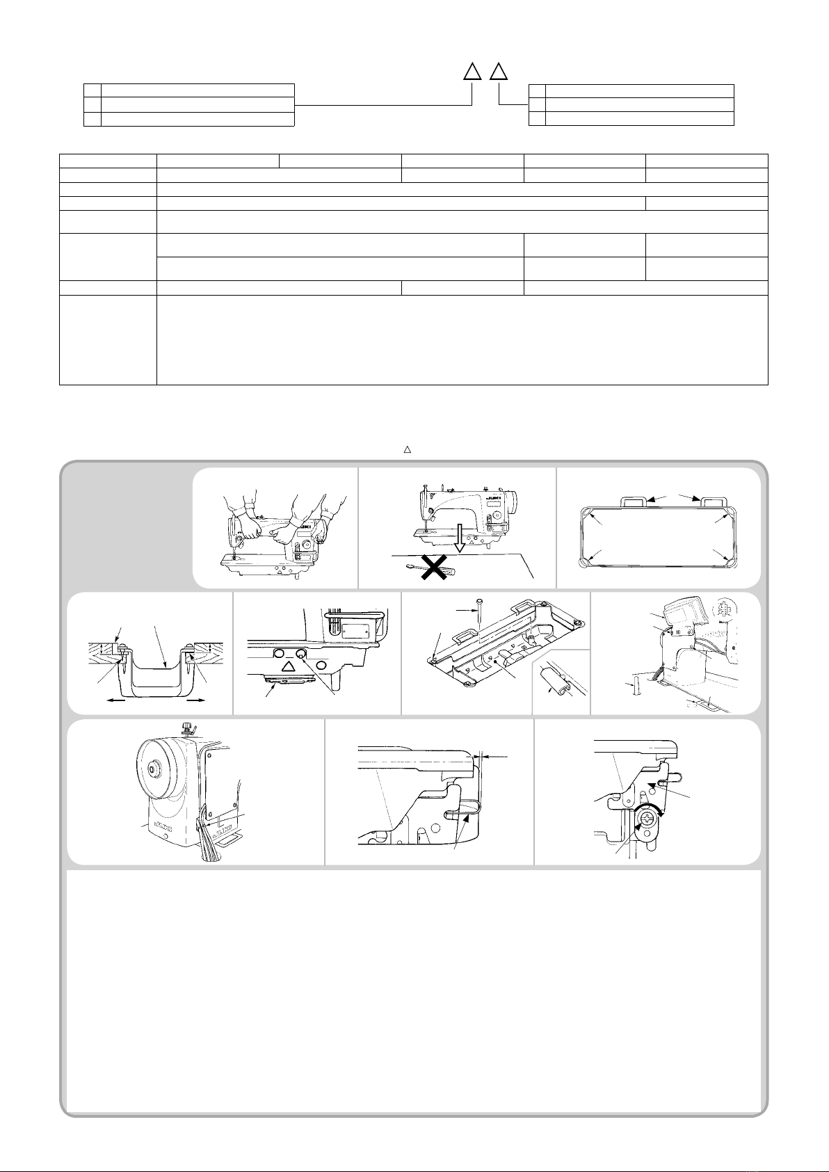
1. INSTALLATION 1) 2)
8)
23.5 mm 19.5 mm
1
2
4
3
A B
3)
4) 5)
1) Carry the sewing machine with two persons as shown in the gure above.
(Caution) Do not hold the handwheel.
2) Do not put protruding articles such as the screwdriver and the like at the location where the sewing machine is placed.
3) The under cover should rest on the four corners of the machine table groove. Mount rubber hinge seat 8 on the table and x it on the table with a nail.
4) Fix two rubber seats 1on side A(operator’s side) using nails 2as illustrated above. Fix two cushion seats 3on side B(hinged side) using a rubber-based adhesive. Then place
under cover 4 on the xed seats.
5) Remove air vent cap 5attached to the machine bed.
(Caution)
1. If the sewing machine is operated without removing air vent cap 5, oil leakage from gear box portion C may occur.
2. Be sure to attach cap 5when transporting the machine head in the state that the machine head is removed from the machine table.
6) Fit knee lifter pressing rod 6. Fit hinge 7 into the opening in the machine bed, and t the machine head to table rubber hinge 8before placing the machine head on cushions 9on
the four corners.
7) Securely attach head support rod !0 to the table until it goes no further. Regarding the control panel !1, remove two side plate xing screws !2, place the rubber packing !3, which is
one of the accessories of the control panel !1, between the head section and control panel !1, then x them together.
(Caution)
1. Do not use the screws supplied as accessories of control panel !1.
2.
Be sure to mount the machine head support bar on the machine table so that its height from the table surface becomes 55 to 60 mm. For the sewing machine provided with
the AK device, be sure to mount the support bar on the table so that its height from the table surface becomes 38 to 43 mm.
8) Bundle cable clip band !4 supplied as accessories of the machine head at the root of the cable.
9) Check to be sure that the table and the safety switch arm !5 are engaged with each other by 2.0 mm to 3.5 mm, with the sewing machine slightly tilted.
(Caution) If the engagement between the table and the safety switch arm is 2 mm or less, Error 302 may occur at the time of startup. Or, if the aforementioned engagement is
3.5 mm or more, safety switch arm !5 may break.
10) If the engagement between the table and safety switch arm !5 is outside the range of 2.0 mm and 3.5 mm, loosen safety switch mounting screw !6 and tilt safety switch !7 in the
direction of the arrow to adjust the engagement of safety switch arm !5 with the table.
9
7
6
4!0
!1
!2 !2
!1
!3
!2
7
8
6),7)
C5
!4
11
3
3
8
6)
9) 10)
!5
2.0 to 3.5 mm
!6
!7

– 2 –
2. ADJUSTING THE HEIGHT
OF THE KNEE LIFTER
3. INSTALLING THE THREAD STAND
3
2
2
1
The standard height of the presser foot lifted using the knee lifter is 10 mm.
You can adjust the presser foot lift up to 15 mm using knee lifter adjust screw
1.
(Caution)
1. Do not operate the sewing machine in the state that the preser foot 3is lifted by 10 mm or more since the needle bar 2comes in contact with the
presser foot 3.
2. Knee lifter initial position
If the adjustment screw 4is over tightened, the sewing machine will operate in a state where the presser foot is lifted up, causing defective
sewing or noise.
1) Assemble the thread stand unit, and insert it in the hole in the machine table.
2) Tighten nut 1.
3) For ceiling wiring, pass the power cord through spool rest rod 2.
1
4
4. LUBRICATION (DDL-9000B-S , -M )
WARNING :
1. Do not connect the power plug until the lubrication has been completed so as to prevent accidents due to abrupt start of the sewing
machine,
2. To prevent the occurrence of an inammation or rash, immediately wash the related portions if oil adheres to your eyes or other parts of your
body.
3. If oil is mistakenly swallowed, diarrhea or vomitting may occur. Put oil in a place where children cannot reach.
Fill the oil tank with oil for hook lubrication before operating the sewing machine.
1) Remove oil hole cap
1
and ll the oil tank with JUKI NEW DEFRIX OIL No.1 (Part No. : MDFRX1600C0) or JUKI MACHINE OIL #7 (Part No. :
MML007600CA) using the oiler supplied with the machine.
2) Fill the oil tank with the oil until the top end of oil amount indicating rod
3
comes between the upper engraved marker line Aand the lower engraved
marker Bline of oil amount indicating window
2
.
If the oil is lled excessively, it will leak from the air vent hole in the oil tank or proper lubrication will be not performed. In addition, when the oil is
vigorously lled, it may overow from the oil hole. So, be careful.
3) When you operate the sewing machine, rell oil if the top end of oil amount indicating rod
3
comes down to the lower engraved marker line of oil amount
indicating window
2
.
(Caution)
1
. When you use a new sewing machine or a sewing machine after an extended period of disuse, use the sewing machine after performing
break-in at 2,000 sti/min or less.
2. For the oil for hook lubrication, purchase JUKI NEW DEFRIX OIL No. 1 (Part No. : MDFRX1600C0) or JUKI MACHINE OIL #7 (Part No. :
MML007600CA).
3. Be sure to lubricate clean oil.
4. Do not operate the machine with the oil hole cap
1
removed. Never remove cap
1
from the oil inlet in any case other than oiling. In addition,
take care not to lose it.
A : Upper engraved marker line
B : Lower engraved marker line
3
1
A
2
B

– 3 –
5. ATTACHING THE NEEDLE
6.
SETTING THE BOBBIN INTO THE BOBBIN CASE
WARNING :
Turn OFF the power before starting the work so as to prevent accidents caused by abrupt start of the sewing machine.
Use the specied needle for the machine. Use the proper needle in accordance with the thickness of thread used and the kinds of the materials.
1) Turn the handwheel until the needle bar reaches the highest point of its stroke.
2) Loosen screw 2, and hold needle 1with its indented part Afacing exactly to the right in direction B.
3) Insert the needle fully into the hole in the needle bar in the direction of the arrow until the end of hole is reached.
4) Securely tighten screw 2.
5) Check that long groove Cof the needle is facing exactly to the left in direction D.
(Caution) When polyester lament thread is used, if the indented part of the needle is tilted toward operator's side, the loop of thread becomes
unstable. As a result, hangnail of thread or thread breakage may occur. For the thread that such phenomenon is likely to occur, it is effective to
attach the needle with its indented part slightly slanting on the rear side.
1
2
C
DB
A
1) Install the bobbin in the bobbin case so that the thread wound direction is clockwise.
2) Pass the thread through thread slit A, and pull the thread in direction C. By so doing, the thread will pass under the tension spring and come out from notch B.
3) Check that the bobbin rotates in the direction of the arrow when thread is pulled.
A
B
C
(1) How to conrm the amount of oil (oil splashes)
7.ADJUSTING THE AMOUNT OF OIL (OIL SPLASHES) IN THE HOOK (DDL-9000B-S , -M )
WARNING :
Be extremely careful about the operation of the machine since the amount of oil has to be checked by turning the hook at a high speed.
* When carrying out the procedure described below in 2), conrm the state that the needle thread from the thread take-up lever to the needle
and the bobbin thread are removed, the presser foot is lifted and the slide plate is removed. At this time, take extreme caution not to allow your
ngers to come in contact with the hook.
1) If the machine has not been sufciently warmed up for operation, make the machine run idle for approximately three minutes. (Moderate intermittent
operation)
2) Place the amount of oil (oil splashes) conrmation paper under the hook while the sewing machine is in operation.
3) Conrm that oil exists in the oil tank.
4) Conrmation of the amount of oil should be completed in ve seconds. (Check the period of time with a watch.)
2 Position to conrm the amount of oil (oil splashes)
Closely t the paper against
the wall surface of the bed.
Hook
Hook driving shaft front bushing
Bed
Oil splashes conrmation paper
3 - 10 mm
* Place the amount of oil (oil splashes) conrmation paper under the
hook and keep it from the hook by 3 to 10 mm to conrm the amount.
1 Amount of oil (oil splashes) conrmation paper
* Use any paper available regardless of the material.
Approx. 70 mm
Approx. 25 mm
Other manuals for DDL-9000B
3
This manual suits for next models
5
Table of contents
Other JUKI Sewing Machine manuals

JUKI
JUKI MO-80CB User manual

JUKI
JUKI DDL-5550 User manual

JUKI
JUKI LK-1900BN User manual

JUKI
JUKI MO-735 User manual

JUKI
JUKI SC-510 Quick start guide

JUKI
JUKI DLM-5200N User manual

JUKI
JUKI MO-104 Quick start guide

JUKI
JUKI DDL-8700B-7 User manual

JUKI
JUKI DDL 552 User manual

JUKI
JUKI DLM-5400NDD-7 User manual

JUKI
JUKI LK-1941 Quick start guide

JUKI
JUKI MO-50e User manual

JUKI
JUKI DDL-8100e User manual

JUKI
JUKI MEB-3200 Series Quick start guide

JUKI
JUKI SC-510 User manual

JUKI
JUKI PLC-2700 Series User manual

JUKI
JUKI dsu-142 User manual

JUKI
JUKI LU-562 User manual

JUKI
JUKI LK-1900A Quick start guide

JUKI
JUKI DLN-5410N User manual