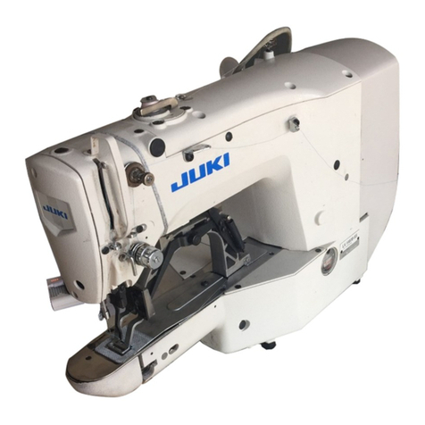
JUKI ACF-172-1790 User manual

iii
INSTRUCTION MANUAL (MACHINE OPERATION)
ACF-172-1790
NOTE : Read safety instructions carefully and understand them before using.
Retain this Instruction Manual for future reference.
1-Needle,Lockstitch,
Automatic buttonholing Machine

1.GENERAL......................................................................................................................... 1
1-1. Features ................................................................................................................................................ 1
1-2. Configuration of the main parts ......................................................................................................... 2
1-3. Operating precautions ......................................................................................................................... 3
2. SPECIFICATIONS ........................................................................................................... 3
3. INSTALLTION ..................................................................................................................4
3-1. Installing the device ............................................................................................................................. 4
3-2. Installing the thread stand .................................................................................................................. 4
3-3. Connecting the power supply ............................................................................................................. 4
3-4. Installing the air hose .......................................................................................................................... 5
3-5. How to operate the air gun ..................................................................................................................5
3-6. Installing the cloth plate ...................................................................................................................... 6
3-7. Installing the machine head ................................................................................................................ 7
(1)Lubrioation .......................................................................................................................................... 7
4. OPERATION AND ADJUSTMENT .................................................................................. 8
4-1. Operating switches and adjusting pneumatic components ............................................................ 8
(1) Power switch ...................................................................................................................................... 8
(2) Pause switch ...................................................................................................................................... 8
(3) Knee switch ........................................................................................................................................ 9
(4) Hand switch ........................................................................................................................................ 9
(5) Workpiece detector switch .............................................................................................................. 10
(6) Preset adjusting knob ..................................................................................................................... 10
(7) Adjusting the air blower .................................................................................................................. 11
(8) Vacuum adjusting metal fittings ..................................................................................................... 13
(9) Sensor to detect the number of garment bodies stacked ............................................................ 13
4-2. Operation of the sewing machine.....................................................................................................14
(1) Inserting the needle ......................................................................................................................... 15
(2) Threading the needle-thread ........................................................................................................... 15
(3) Threading the bobbin case .............................................................................................................. 16
(4) Adjusting the bobbin thread tension ............................................................................................. 16
(5) Installation of bobbin case .............................................................................................................. 17
(6) Installing the knife............................................................................................................................ 17
(7) Remove and installing the bobbin case......................................................................................... 18
4-3. Adjusting the seam allowance ..........................................................................................................19
(1) Adjusting distance A ....................................................................................................................... 19
(2) Adjusting distance B ....................................................................................................................... 19
4-4. Adjusting the carriage lamp .............................................................................................................. 20
(1) Adjusting the position of the clamps .............................................................................................20
(2) Adjusting the clamping force ..........................................................................................................20
4-5. Adjusting the stacking board of the stacker ................................................................................... 21
5. Operation ...................................................................................................................... 22
CONTENTS
6. MAINTENACE................................................................................................................ 24
6-1. Adjusting the needle-to-hook relation ............................................................................................. 24
6-2. Adjusting the needle thread trimmer ............................................................................................... 25
6-3. Adjusting the presser bar pressure ................................................................................................. 26
6-4. Adjustment of the bobbin presser unit ............................................................................................ 26
6-5. Thread tension ................................................................................................................................... 27
6-6. Removing dust near the bobbin case .............................................................................................. 28
6-7. Cleaning the cooling filter ................................................................................................................. 28
6-8. Cleaning the vacuum filter ................................................................................................................ 29
6-9. Draining of the air regulator .............................................................................................................. 29
6-10. Replacing the clamp cushion ......................................................................................................... 30
6-11. Cleaning the carriage and lubricating to the drive section .......................................................... 30
6-12. Replacing the fuse ........................................................................................................................... 31
7. GAUGE COMPONENTS................................................................................................ 32
8. TROUBLES AND CORRECTIVE MEASURES ............................................................. 35
9. INITIAL VALUE DATA FOR EACH SHAPE TABLE....................................................... 37

−1 −
1. GENERAL
Mainly consisting of a sewing machine, preset board, carriage, stacker, the ACF-172-1791RS indexer is
designed to automatically carry out a series of operations starting sewing button on the front top-center
strips of men’s shirts, etc. and ending with stacking of workpieces.
1-1 Features
1) Thematerialfeedmechanismallowsthematerialtobefedquicklyat
accuratintervals.
2) Thenumberofbuttonholesorthefeedtothesewingamountcanbeeasilyset
orchangedwiththekeysonthecontrolpanel.Twentydifferentpatternscanbe
storedinmemory,whichenablestheoperatortoquicklyrespondtothefrequent
setupchanges.
3) Thematerialisautomaticallyfedtosewingpositionafterithasbeenplacedon
thesettingposition.Themachineautomaticallyperformsaseriesofoperations,
includingsewing,threadtrimmingandstaking.
4) Theoperatorcansetthenextmaterialtobesewnwhilethemachineisstill
sewing, allowingtheoperatortohaveenoughtoattendonseveralmachines.
5) Thankstothepresettingmechanism,itispossiblefortheoperatortoattendon
fourmachineswithoutcausingoneofthemtostandidleorfortheoperator
himself/herselftobecomeidlewhentowpiecesofgarmentareseton.
6) Theclampingmechanismclampsthematerialsecurelywithoutallowingany
slippageduringthesewingoperationfrominsertingtostacking.
7) Buttonholescanbesewnalsothefrontto-centerstripsofladiesユwear.9)The
machinehasvariousmodeswhileenableself-diagnosiswhenanerroroccurs.
10) Itisalsoequippedwithaworkpiecedetectormechanismwhicheliminatesa
sewingstarterror.
11) Theamountoffinishedproductsstackedonthestackercanbedetected.

−2 −
1-2.Configuration of the main parts
!3 Cloth palate
!4 Handle of the cloth plate
!5 Tool box
!6 Thread stand
!7 Filter box
!8 Machine head pause switch
9
2
451
!0
!2 !5
!1 6
7
!4
!3
!7
8
!6
1 Sewing machine head
2 Preset board
3 Carriage
4 Stacker
5 Control panel
6 Power switch
7 Knee switch
8 Pause switch
9 Hand switch
!0 Workpiece detector switch
!1 Air gun
!2 Preset adjusting knob (supplied with
the machine in the accessory box)
3
!8

−3 −
1. Before you put the machine into operation for the first time after the set-up, clean it thoroughly.
2. This machine corresponds to the power supply voltage 200 to 240V.
3. Never use the machine in the state where the voltage type is different from the designated one.
4. Operate the machine with the air pressure set to 0.5Mpa.
CAUTION:
To avoid malfunction and damage of the machine, confirm the following.
2. SPECIFICATIONS
(1) main unit
1Feed interval
2Overall feed amount
3Number of buttonholes which
can be sewn
4Distance from the top end of
the garment body to the
1st buttonhole
5distance from the side end of
the garment body to the
buttonhole
6Applicable garment size that
cat be sewn
Number of patterns that can
be stored in memory
Power supply
Power source frequency
Power consumption
Operating air pressure
Air consumption
Machine dimensions
Weight
1-3. Operating precautions
: 0 to 610 (0. to 24”)
(2) Sewing machine components
1Machine head
2Sewing speed
3Stitch length
4Size (knife size)
5Needle
6Lubricating oil
7Number of stitches
1
4
2
6
6
5
: LBH-79RS-1ACH
: Max. 4,000 rpm
: Max. 25 mm X sewing width 4 mm
: 6.4 to 19.1 mm (1/4 to 3/4”)
: DPx5 #11J to #14J
: JUKI New Defrix Oil No.1
: 0.2 to 2.5
: 300 kg
: Width 1,910mm
Depth 850mm
Table Height 920 mm
: 240 Nl/ min . or less
: 0.5 MPa
: 1000 VA (supply voltage ±10% or less)
: 50/60 Hz
: 200 to 240V(3-phase/single phase) (Rated voltage ±10% or less)
(Without voltage changeover)
: 20
: Width 220 to 420 mm
(8.7 to 16.5”)
Length 400to 880 mm
(15.7 to 34.6”)
: 7 to 21 mm
(0.3 to 0.8”)
: 0 to 140 mm
(0 to 5.5”)
: 1 to 20 ps. (the machine is set to
the independent sewing mode
when sewing only one buttonhole
on the material. )
: 610 mm (24”)

−4 −
3-3. Connecting the power supply
1) First confirm that power switch in “OFF”, then
connect the power cord to the power supply.
2) If the driving pulley rotates in the reverse direction,
change the connection of two terminals of the three
cables.
3) Turn ON the power, and then check the direction
of the fan of the blower motor against the seal
showing the direction of rotation attached on the
fan cover of the blower motor.
4) If the fan rotates in the reverse direction, change
the connection of the power cord to the reverse
position on the plug side of the power cord. Then
re-check the direction of rotation of the fan of the
blower motor to make sure of the normal rotation.
1. Running the pulley in the reverse
direction might case the sewing
machine to malfunction.
2. Be sure to check the direction of rotation
of the sewing machine motor and that
of the blower motor
3. INSTALLTION
1) Securely fix the device in place moving brakes 1
of the four outsize casters provided with a brakes
1of the four out side casters provided with a break
in the direction of the arrow.
2) If the floor on which the device is to be installed is
not flat and smooth, loosen nuts 2adjust the
height of the device properly and firmly tighten the
nuts.
3) Finally, lower adjusters 3until the caster do not
rise above the floor surface, and fix the adjusters
using nuts 4.
3-1. Installing the device
2
1
1
4
3
2
1
3-2. Installing the thread stand
1) Assemble the thread stand unit, and fix the
assembly in the hole in the table as shown in the
figure.
2) Tighten locknuts 1 so that they securely hold the
thread stand assembly.
3) In the case of ceiling wiring, pass the power cable
through spool rest rod 2.

−5 −
3-4. Installing the air hose
1) Insert air hose 1into one-touch joint 2 supplied
with this unit, and fix it using metal fittings or the
like.
2) Insert one-touch joint 2into joint 3until it clicks.
3) Set the air pressure gauge to 0.5 MPa. To adjust,
raise knob 5of regulator 4in direction A, and
turn knob 5clockwise (direction C) to increase
the air pressure, or turn the knob counter-clockwise
(direction C) to increase the air pressure, or turn
the knob counter-clockwise (direction D) to
decrease the air pressure. When the air pressure
gauge has been set to 0.5 MPa press knob 5in
direction Buntil it clicks. The sound indicates that
the gauge has locked.
When bottle 6is filled with waiter, be
sure to drain off the water by removing
one-touch joint 2from regulator 4, and
by pressing drain button 7.
Drain off the water every time the
machine is used , either before or after
operation.
3-5. How to operate the air gun
1) The amount of air to be blown from the air gun is
changed by turning nozzle 1mounted at the top
end of air gun.
2) Turning the nozzle in the direction of the solid
arrow will decrease the amount of air to air to be
blown from the gun.
1
5
C
D
B
A
3
2
1
4
6
7

−6 −
3-6. Installing the cloth plate
1) Loosen handle 1of the cloth pate. Then bring
cloth prate 2to the desired position, and tighten
handle 1.
2) The cloth plate can be installed either the right-or
left-hand side of the unit. Loosen handle 1, and
draw out cloth plate 2.Remove two screw 3,
move cloth plate support bar 4to the position
shown in the figure and tighten screws 3. Fit the
cloth plate on the support bar, and fix the table at
the desired position. (If you wish to place a material
setting table on cloth side of the unit, the cloth plate
(asm.) G50281720B0 is separately available.)
Be sure to use the cloth plate only to
place the material on it. Do not lean
against the or sit on it.
2
3
4
1
3
4
Tighten Loosen

−7 −
1) Lubricating oil to oiling tank
™Fill the oiling tank with New Defrix Oil No.1 up to the level indicated by “MAX” 1.
2) Adjusting the lubrication for the sewing hook
™Adjust the amount of oil supplied to the sewing hook by loosening lock nut Úñ and turning oil amount
adjusting screw 3.
™Amount of supplied oil is reduced when turning the screws 3clockwise.
™Fix the screw with lock nut 2after adjusting the lubrication for the sewing hook.
™When you first operate your sewing machine after set-up or after an extended period of disuse,
remove the bobbin case and apply a few drops of oil to the hook race. In addition, apply a few
drops oil from oiling hole 5in hook driving shaft front metal 4to soak the inside felt in oil.
WARNING :
To protect against possible personal injury due to abrupt start of the machine, be sure to start the
following work after turning the power off and ascertaining that the motor is at rest.
1
2
3
(1) Lubrioation
Detailed diagram of oil amount adjusting section
Decrease
Oil amount
Increase
Oil pipe
5
4
3
2
3-7. Installing the machine head

−8 −
4. OPERATION AND ADJUSTMENT
WARNING:
Turn OFF the power before staring the work so as to prevent accidents caused by abrupt start of the
4-1. Operating switches and adjusting pneumatic components
(1) Power switch
Use this switch to turn ON / OFF the power to the unit.
(2) Pause switch, Machine head pause switch
Use this switch to stop the machine from running.
5Workpiece detector switch
6Preset adjusting knob
3Knee switch
2Pause switch
1Power switch
4Hand switch
Sensor to detect
the number of
garment bodies
stacked
!2
!1 Vacuum adjusting
metal fittings
!0
8
9
Speed
controller of
the blower
for the
lifting the
workpiece
7Speed controller
of the blower for
the peeling off
the workpiece
Speedcontroller of
the blower for the
sucking
the workpiece
Speed
controller of the
blower for the
carriage
2Machine head pause switch

−9 −
(3) Knee switch
The height of the switch can be adjusted in the three
stages. (It has been factory-adjusted to the middle
stage at the time of delivery.) Loosen two screws 1
in the reverse side of the knee switch, and fix the
switch at a height where you can operate it with ease.
The switch is used as the start switch under the A
mode, and is used as the preset cancel switch under
the B mode.
Whether the knee switch or the hand switch is used
as the start switch can be selected with the memory
switch dara .
(For the setting procedure of the selection of the start
switch under A mode/B mode, refer to "2-17.
Changing the memory switch data " in the section of
PANEL OPERATION.)
Be careful not to drop the knee switch
when removing the screw.
(4) Hand switch
This switch is used as the start switch or the preset cancel switch.
(Refer to the aforementioned "Knee switch".)
If the electricity is cut off when material is being
brought to the sewing position and preset board 1
and carriage 1come in contact with each other,
discharge air from the machine, slightly press preset
board 1back ward, raise carriage 2by hand, and
move preset board 1toward you to return it to its
home position. Then, connect the air to the machine.
To discharge air from the unit, press one-touch joint
3in the direction of the arrow, and remove hose 4.
For the connecting procedure, refer to "3-4.
Connecting the air hose".
1
2
3
4
1

−10 −
(5) Workpiece detector switch
This switch prevents a malfunction when there is no
workpiece set on the machine.
If either one of two detector switches 1detects a
workpiece, the machine is actuated.
Take care not to place anything other than the sewing
products or hands on detector switches 1.
If using a piece of light absorbing black material, the
detector sensor may be inoperative. In this case, the
detecting function can be inoperative by selecting the
memory switch No. .
(Refer to "2-17. Changing the memory switch data"
in the section of PANEL OPERATION.)
(6) Preset adjusting knob
Use this knob to adjust the seam allowance.
Insert preset adjusting knob 1which is supplied in
the accessory box into the hole, and turn the knob to
set the seam allowance to the value indicated by scale
marker 2. (Refer to "4-3. Adjusting the seam
allowance".)
After the adjustment, return knob 1to the tool box to
prevent it from being lost.
1
2
1

−11 −
(7) Adjusting the air blower
1) The air blower is provided with four blow pipes
as illustrated in the figure on the left. The soled
arrows show the air blowing direction of the
respective pipes. The name and function of
each components is as follows:
2) The speed controllers used to adjust the air blow
of air blow pipes 1to 4are those shown in
the figure on the left.
1Speed controller of the blower for the carriage
2Speed controller of the blower for the lifting
the workpiece
3Speed controller of the blower for the sucking
the workpiece
4Speed controller of the blower for the peeling
off the workpiece
3) Table of relationship between the adjustment
values of the speed controllers at the time of
delivery and the thickness of the material
To be used for
bellowing down the
workpiece
To be used for
staking the
workpiece
H
15
4
62
7
3
1Blower for the
carriage
2Blower for lifting the
workpiece
3Blower sucking the
workpiece
4Blower peeling off the
workpiece
5Machine head
6Preset table
7Stacking board
Material
Light weight small ⇔Heavy .Large
Decrease Increase
No. H(mm)
Amount of air to be blown
4
3
2
1
1
2
3
4
14 ~ 15
13 ~ 14
14 ~ 15
13 ~ 14

−12 −
4) Turn knob 1of the speed controller in the direction
of the arrow to increase the amount of air to be
blown. After the adjustment, fix the knob at the
adjusted position using locknut 2.
Adjusting the amount of air to be blow
while the machine is in operation is very
dangerous. Be to turn OFF the power to
the machine starting the adjustment.
5) Adjusting the air blower for blowing down the
workpiece
If sewing a heavy-weight material or a large-size
material, fully open speed controller 1first. If the
workpiece cannot be easily blown down, gradually
loosen speed controller 2to increase the amount
of air to be blown properly.
If sewing a light-weight material or floppy material,
set speed controller 2to the value adjusted of air
to be blown.
6) Adjust the air blower for stacking the workpiece
If sewing a heavy-weight material or a large-size
material, loosen speed controller 3and 4to in
increase the amount of air to be blown properly.
If sewing a light-weight material, set speed
controller 3to be the value adjusted at the time
of delivery and tighten speed controller 4to
increase the amount of air to be blown.
1
2
1
3
2
4

−13 −
7) Adjusting the air blower for the needle bar
When dust collected on the needle bar area falls
and is caught in the seams, adjust the direction and
strength of the air blower.The air blower blows dust
away and prevents dust from falling under
needle. For the direction of the air blower, correct
the installation of the pipe.Adjust the air blower so
that air blows as near as the machine arm jaw area.
Press and turn the manual switch of solenoid valve
No. 7 to check the motion.Strength of the air blow
is adjusted with the speed controller.When the
manual switch of solenoid valve No. 7 is pressed
and turned, the pusher is actuated and
simultaneously the needle bar air blower is actuated.
Return the manual switch after the adjustment since
the manual switch is locked with it pressed and
turned.Adjust the speed controller located on the
black pipe branched from the yellow pipe connected
from solenoid valve No. 7.
Air blow is actuated during machine operation when
continuously performing sewing. Take care not to
excessively increase the amount of air to be blown
so that the sewing is not affected.
Standard adjustment value : 9.5 ±±
±±
±0.5 mm
Air blow pipe
Solenoid valve No. 7
Manual switch
9.5 ±±
±±
±0.5mm

−14 −
(8) Vacuum adjusting metal fittings
They are used to adjust the vacuum suction force of
the preset board for sucking the workpiece.
Adjustment is carried out by turning metal fitting 1.
For the normal operation, 2in the metal fitting should
not be closed. If sewing a large-size material should
not be closed. If sewing a large-size material or a
coarse texture, close the hole 2.
To keep the appropriate suction force, clean
the filter inside filter box 3at regular
intervals. (Refer to "6-8. Cleaning the
vacuum filter".)
(9) Sensor to detect the number of garment bodies stacked
1) Sensor 2mounted on cylinder 1which driver
pusher 4detects the thickness of garment bodied
stacked on stacking board 3when actuating the
stacker.
2) You can let the alarm occur at the time when the
thickness of garment bodies stacked on the board
reaches any desired value specified by change
the position of sensor 2with a Phillips type
screwdriver. (Distance Shas been factory-
adjusted to 40 mm at the time of delivery. The value
is equivalent to the height reached when stacking
approximately 120 to 140 garment bodies made
of T/C broadcloth. Moving sensor 2to the right
will make the alarm occur earlier.)
Note that the sewing machine does not
stop operation when this alarm occurs.
2
1
3
4
2S
1
3

−15 −
(Cotton thread, spun thread)
(2) Threading the needle-thread
1
A
(1) Inserting the needle
1
7
3
2
6
8
5
9
!0
4
!1
!2
4-2. Operation of the sewing machine
Hold needle with its recessed part facing toward the operator side A,
insert the needle fully into the needle clamping hole, and tighten needle
setscrew 1. Use a DPx5-(#11J, #14J).
When attaching the needle, turn OFF the power to the
motor.
WARNING :
To protect against possible personal injury due to abrupt start of the machine, be sure to start the
following work after turning the power off and ascertaining that the motor is at rest.
WARNING :
To protect against possible personal injury due to abrupt start of the machine, be sure to start the
following work after turning the power off and ascertaining that the motor is at rest.
Pass the needle thread in the order 1to !2 as shown in the figures.
The threading can be done easily by using the needle threader supplied with the machine.
Change the thread guide threading method according to the thread to be used.
(Synthetic filament thread)

−16 −
Rotating direction of bobbin and threading
1) Fit the bobbin so that it rotates in the direction of the arrow.
2) Pass the thread through thread slit 1, then through under the tension spring 2, again through thread slit
3, and pull the thread from 4.
3) Threading at 4for purl stitching is different from that for whip stitching. So, be careful.
Whip stitch
Bobbin case
Bobbin
Purl stitch
(3) Threading the bobbin case
1
24
3
4
(4) Adjusting the bobbin thread tension
Adjust the bobbin thread tension as given below when the bobbin thread is pulled up at the position where
thread slit 1of bobbin case comes up.
Turning tension adjust screw 2clockwise will increase bobbin thread tension, and turning it counterclockwise
will decrease the tension.
Adjust the bobbin thread tension to lower for synthetic filament thread, and to higher for spun thread. The
thread tension is higher by approximately 0.05N when the bobbin case is set to the hook since idle-prevention
spring is provided.
When bobbin thread tension is adjusted, make sure of the needle thread tension setting of the memory
switch.(Refer to "2-9. Changing the needle thread tension" in the section of PANEL OPERATION.)
1
2
Purl stitch 0.05 to 0.15N
To such an extent that bobbin case quietly comes down when
holding thread end coming from bobbin case and shaking it
quietly up and down.
To such an extent that bobbin case barely comes down when
holding thread end coming from bobbin case and shaking it
somewhat strongly.
Whip stitch 0.15 to 0.3N

−17 −
When replacing the knife with a new one, perform as
follows.
1) Knife 1can be easily removed together with the
washer when removing knife retaining screw 2.
2) Adjust so that the knife, when lowered the knife
bar by hand, is spaced 1 to 2 mm away from the
top surface of the throat plate as illustrated in the
sketch. Then, be sure to place the washer and
tighten the knife retaining screw.
(6) Installing the knife
1
2
1〜2mm
(5) Installation of bobbin case
1) Lift up and hold bobbin case latch lever between
two fingers.
2) Push the bobbin case into the hook so that it is
supported by the hook shaft 1and then snap in
the latch lever.
Press the bobbin case until the predetermined
position is reached, and it will click.
1. If the bobbin case is out of the
predetermined position, it can jump
out from the hook to cause the
needle thread to tangle on the hook
shaft. Check to be sure that the
bobbin case is properly installed in
the correct position.
2. There is a difference in the shape
of bobbin case between the
standard hook and the dry one.
They have nothing in common with
each other.
1
WARNING :
To protect against possible personal injury due to abrupt start of the machine, be sure to start the
following work after turning the power off and ascertaining that the motor is at rest.
WARNING :
To protect against possible personal injury due to abrupt start of the machine, be sure to start the
following work after turning the power off and ascertaining that the motor is at rest.
Inch →mm CONVERSION TABLE
In case the cloth cutting knife on hand is indicated in
inch, set the length of cloth cutting (knife size) in mm
using the inch →mm conversion table on the left side.
Sewing data is the length of cloth cutting.
Refer to "2-7. Changing the sewing data" in the section
of PANEL OPERATION.
Knife size
1/4
3/8
7/16
1/2
9/16
5/8
11/16
3/4
13/16
7/8
1
1 1/8
1 1/4
1 3/8
1 1/2
Indication of mm
6.4
9.5
11.1
12.7
14.3
15.9
17.5
19.1
20.6
22.2
25.4
28.6
31.8
34.9
38.1
Other manuals for ACF-172-1790
3
Table of contents
Other JUKI Sewing Machine manuals

JUKI
JUKI LU-1510 User manual

JUKI
JUKI PLC-2700 Series User manual

JUKI
JUKI HZL-F series User manual

JUKI
JUKI MO-6900J Series Quick start guide

JUKI
JUKI SADE User manual

JUKI
JUKI MO-102 User manual

JUKI
JUKI SC-920 User manual

JUKI
JUKI LZH-1290-4 User manual

JUKI
JUKI UT55 User manual

JUKI
JUKI DDL-8700A-7 User manual

JUKI
JUKI LU-2828NV User manual

JUKI
JUKI LU-2810-6 User manual

JUKI
JUKI PLK-J4040R3 User manual

JUKI
JUKI LZ-2284N-7 User manual

JUKI
JUKI MH-481 User manual

JUKI
JUKI LK-1901AN User manual

JUKI
JUKI PLC-1710 User manual

JUKI
JUKI IT-10 User manual

JUKI
JUKI UnionSpecial 35800BLWG Setup guide

JUKI
JUKI MS-1261A-DWS User manual