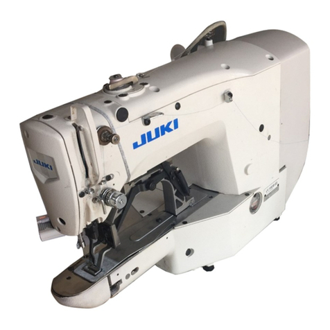
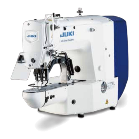
JUKI AC-172N-1790AN User manual

INSTRUCTION MANUAL
AC-172N-1790AN

i
CONTENTS
I. MACHINE OPERATION............................................................................... 1
1. GENERAL...................................................................................................................... 1
1-1. Features ..........................................................................................................................................1
1-2. Conguration of the main parts....................................................................................................2
1-3. Operating precautions...................................................................................................................3
2. SPECIFICATIONS ......................................................................................................... 3
3. INSTALLATION.............................................................................................................. 4
3-1. Removing the machine head xing plate ....................................................................................4
3-2. Connecting the power supply.......................................................................................................5
3-3. Installing the air hose ....................................................................................................................5
3-4. Lubrication......................................................................................................................................6
3-5. Installing the panel.........................................................................................................................8
3-6. Installing the eye protection cover............................................................................................... 9
3-7. Installing the thread guide ............................................................................................................9
3-8. Installing the thread stand ............................................................................................................9
3-9. Installing the marking light .........................................................................................................10
3-10. Adjusting the marking light.......................................................................................................12
3-11. Installation and adjustment of the material edge detecting sensor (asm.) .......................... 13
3-12. Assembly and adjustment of the auxiliary clamp................................................................... 18
4. OPERATION AND ADJUSTMENT .............................................................................. 26
4-1. Operating switches and adjusting pneumatic components .................................................... 26
4-2. Operation of the sewing machine...............................................................................................33
4-3. Adjusting the seam allowance....................................................................................................37
4-4. Adjusting the carriage clamp......................................................................................................38
4-5. Adjusting the sub clamp ............................................................................................................. 39
4-6. Adjusting the stacking board of the stacker ............................................................................. 41
4-7. Preventive measure against the material dropping during stacking...................................... 41
5. OPERATION ................................................................................................................ 42
II.
OPERATION SECTION (WITH REGARD TO THE PANEL) .............................................44
1. WHEN USING IP-420 .................................................................................................. 44
1-1. Name of each section of IP-420 ..................................................................................................44
1-2. Buttons to be used in common ..................................................................................................45
1-3. Basic operation of the sewing machine.....................................................................................46
1-4. LCD display section under AC mode ......................................................................................... 47
1-5. Performing AC pattern selection ................................................................................................ 52
1-6. Performing re-sewing ..................................................................................................................53
1-7. Winding bobbin thread................................................................................................................ 55
1-8. Using counter............................................................................................................................... 56
1-9. Performing new register of AC pattern. ..................................................................................... 59
1-10. Copying AC pattern ................................................................................................................... 65
1-11. Changeover of men's and ladies' wear. ................................................................................... 66
1-12. Naming the pattern ....................................................................................................................67
1-13. Changing over the pair stack.................................................................................................... 68

ii
2. OPERATION OF THE SINGLE UNIT OF SEWING MACHINE AND SETTING
PROCEDURE (LBH MODE) ..................................................................................... 69
2-1. LCD display section at the time of independent sewing.......................................................... 69
2-2. Performing LBH pattern No. selection....................................................................................... 73
2-3. Performing sewing shape selection........................................................................................... 74
2-4. Performing re-sewing under LBH mode ....................................................................................75
2-5. Performing new register of LBH pattern....................................................................................78
2-6. Sewing shape list......................................................................................................................... 80
2-7. Changing sewing data................................................................................................................. 81
2-8. Inputting the work clamp type ....................................................................................................89
2-9. Changing needle thread tension ................................................................................................91
2-10. Setting procedure of sewing data with/without edit............................................................... 93
2-11. Copying LBH sewing pattern .................................................................................................... 94
2-12. Registering sewing data to customize button......................................................................... 96
2-13. Changing sewing mode............................................................................................................. 98
2-14. LCD display section at the time of continuous stitching....................................................... 99
2-15. Performing LBH continuous stitching ...................................................................................103
2-16. Explanation of plural motions of knife................................................................................... 107
3. CHANGING MEMORY SWITCH DATA ..................................................................... 110
3-1. Changing procedure of memory switch data.......................................................................... 110
3-2. Memory switch data list............................................................................................................. 112
4. ERROR CODE LIST .................................................................................................. 117
5. MESSAGE LIST......................................................................................................... 127
6. USING COMMUNICATION FUNCTION .................................................................... 130
6-1. Handling possible data.............................................................................................................. 130
6-2. Performing communication by using the media..................................................................... 131
6-3. Performing communication by using USB.............................................................................. 134
6-4. Take-in of the data......................................................................................................................134
7. PERFORMING FORMATTING OF THE MEDIA........................................................ 137
8. PERFORMING KEY LOCK ....................................................................................... 138
9. DISPLAYING VERSION INFORMATION .................................................................. 139
10. USING CHECK PROGRAM .................................................................................... 140
10-1. Displaying the check program screen ...................................................................................140
10-2. Performing needle thread trimmer origin adjustment.......................................................... 141
10-3. Performing bobbin thread trimmer origin adjustment ......................................................... 142
10-4 Performing sensor check......................................................................................................... 143
10-5. Performing LCD check ............................................................................................................146
10-6. Performing touch panel compensation .................................................................................147
10-7. How to carry out the external output check .......................................................................... 149
10-8. How to adjust the adjuster ......................................................................................................151
10-9. How to adjust the cloth trimming knife motor origin............................................................ 152
10-10. How to correct the presser foot pressure............................................................................ 153
11. INFORMATION FUNCTION..................................................................................... 154
11-1. Observing the maintenance and inspection information ..................................................... 155
11-2. Inputting the inspection time .................................................................................................. 157
11-3. Releasing procedure of the warning ...................................................................................... 159
11-4. Observing the production control information ..................................................................... 160

iii
11-5. Performing setting of the production control information................................................... 163
11-6. Observing the working measurement information ............................................................... 166
12. TRIAL SEWING FUNCTION.................................................................................... 169
12-1. Performing trial sewing ..........................................................................................................169
12-2. Vector parameter list................................................................................................................172
12-3. Thread tension value display color list.................................................................................. 173
13. COMMUNICATION SCREEN OF MAINTENANCE PERSONNEL LEVEL............. 174
13-1. Data which are possible to be handled.................................................................................. 174
13-2. Displaying maintenance personnel level............................................................................... 175
14.
INFORMATION SCREEN OF THE MAINTENANCE PERSONNEL LEVEL.............176
14-1. Display of error record ............................................................................................................176
14-2. Display of the cumulative working information .................................................................... 178
III. MAINTENANCE OF SEWING MACHINE.............................................. 179
1. MAINTENANCE......................................................................................................... 179
1-1. Adjusting the needle-to-hook relation ..................................................................................... 179
1-2. Adjusting the needle thread trimmer ....................................................................................... 180
1-3. Adjusting the cloth presser pressure ...................................................................................... 180
1-4. Adjustment of the bobbin presser unit .................................................................................... 181
1-5. Thread tension ...........................................................................................................................181
1-6. Replacing the clamp cushion ...................................................................................................182
1-7. Adjusting the machine head ..................................................................................................... 182
1-8. Replacing the fuse .....................................................................................................................183
1-9. Disposal of batteries..................................................................................................................186
2. GAUGE COMPONENTS ........................................................................................... 188
3. DAILY MAINTENANCE ............................................................................................. 189
3-1. Removing dust near the bobbin case ......................................................................................189
3-2. Cleaning the vacuum lter ........................................................................................................189
4. TROUBLES AND CORRECTIVE MEASURES ......................................................... 190
IV. INITIAL VALUE DATA FOR EACH SHAPE TABLE.............................. 192

– 1 –
1) The material feed mechanism allows the material to be fed quickly at accuratintervals.
2) The number of button holes and the amount of feed can be set and changed with ease by operating the
touch panel. Twenty dierent patterns can be stored in memory, which enables the operator to quickly
respond to the frequent setup changes.
3) The material is automatically fed to sewing position after it has been placed on the setting position. The
machine automatically performs a series of operations, including sewing, thread trimming and stacking.
4) The operator can set the next material to be sewn while the machine is still sewing, allowing the opera-
tor to have enough time to attend on several machines.
5) Thanks to the presetting mechanism, it is possible for the operator to attend on four machines without
causing one of them to stand idle or for the operator himself/herself to become idle when two pieces of
garment are set on.
6) The clamping mechanism clamps the material securely without allowing any slippage during the sewing
operation from inserting to stacking.
7) Buttonholes can be sewn also to the front to-center strips of ladies wear.
8) The machine has various modes while enable self-diagnosis when an error occurs.
9) It is also equipped with a workpiece detector mechanism which eliminates a sewing start error.
I. MACHINE OPERATION
Mainly consisting of a sewing machine, preset board, carriage, stacker, the AC-172N-1790AN indexer is
designed to automatically carry out a series of operations starting with sewing buttonholes on the front
top-center strips of men’s shirts, etc. and ending with stacking of workpieces.
1-1. Features
1. GENERAL
Other manuals for AC-172N-1790AN
1
Table of contents
Other JUKI Sewing Machine manuals

JUKI
JUKI MO-6900J Series Quick start guide

JUKI
JUKI LK-1850 Series User manual

JUKI
JUKI LZ-2290A-SR/IP-100D/SC-916 User manual

JUKI
JUKI MO-6000 Series User manual

JUKI
JUKI AP-876/IP-420 User manual

JUKI
JUKI PLC-2710N-7 User manual

JUKI
JUKI LK-1900AN-SS User manual

JUKI
JUKI PLC-1710 User manual

JUKI
JUKI LBH-1702 User manual

JUKI
JUKI MP-G10-NC User manual