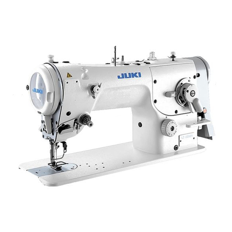
JUKI LZ-2290C/X73257 User manual

LZ-2290C / X73257
INSTRUCTION MANUAL / PARTS LIST
This Instruction Manual only describes the setup and operation methods for the stitch skipping/double
catching detection device (SD-29) for the LZ-2290C Series of sewing machine.
Refer to the documents (Instruction Manual and Safety Precautions) for the LZ-2290C Series of sewing
machine for descriptions about parts other than the stitch skipping/double caching detection device (SD-29).

CONTENTS
Preface................................................................................................................................. 1
1. Parts supplied with the device (Parts of the SD-29 device) ....................................... 2
2. Installing the under cover.............................................................................................. 3
3. Writing the software for electrical components (for a limited time).......................... 4
4. Assembling the sensor amplifier components............................................................ 6
5. Assembling the sensor head components .................................................................. 7
6. Connecting the cords (1) - On the sensor amplifier side - ......................................... 8
7. Connecting the cords (2) - Sensor head side -............................................................ 9
8. Adjusting the sensor position..................................................................................... 11
9. Turning the sensor ....................................................................................................... 14
10. DPC function............................................................................................................... 16
11. Solution viewer function ............................................................................................ 18
11-1. Specification values and handling method .................................................................. 18
11-2. Procedure for checking the solution viewer ................................................................ 19
11-3. How to turn ON and OFF the solution viewer .............................................................. 19
12. Setting the functions on the operation panel .......................................................... 20
12-1. Messages on the operation panel ................................................................................. 20
12-2. Set values of memory switches .................................................................................... 21
12-3. Sewing pattern data........................................................................................................ 23
13. Flow of work by maintenance personnel ................................................................. 24
13-1. Replacing the thread, material and gauge ................................................................... 24
13-2. Procedure for replacing the hook and for adjusting the hook timing ....................... 26
14. Operating and bobbin-changing procedures .......................................................... 28
14-1. Sewing method ............................................................................................................... 28
14-2. Method for changing the bobbin................................................................................... 29
14-3. Method for unlocking and locking the index plunger (at two locations)................... 30
15. Parts list ...................................................................................................................... 31
16. Optional parts ............................................................................................................. 34
17. Additional function for the standard sewing machine............................................ 36
17-1. Low tension sewing (AT low output mode) .................................................................. 36
17-2. Correction of the shape length of sewing pattern....................................................... 37
18. Troubleshooting ......................................................................................................... 38
・
The work required to set up the sewing machine is described in "2. Installing the under
cover" p.3 to "12. Setting the functions on the operation panel" p.20.
・
The work required before putting the sewing machine into sewing process should be
carried out referring to
"13. Flow of work by maintenance personnel" p.24 to 26.
・
Operators in charge of sewing should refer to "14. Operating and bobbin-changing
procedures" p.28 to 30.
i
– 1 –
[ SD-29 ]
SD-29 is the device that displays errors on the operation panel to notify the occurrence of below-stated mal-
functions including stitching failure.
Stitching failure "stitch skipping" has occurred.
Stitching failure "needle thread breakage" has
occurred.
M640
Stitch skipping is detected
Stitching failure "double catching" has occurred. M641
Double catching is detected
Sewing machine runs with neither bobbin nor bobbin case.
Sewing machine runs while the operation plate (sensor) of
the SD-29 is not put in its normal position.
M642
Light quantity of the stitch
skipping detection sensor has
decreased
The timing to display errors (to stop the sewing machine immediately, to stop the sewing ma-
chine at the time of thread trimming, etc.) and the number of times of occurrence of an error
until the error is detected (when thread skipping occurs twice, etc.) can be changed by chang-
ing the relevant settings on the operation panel.
Normally, the needle thread crosses this side of the bobbin case once per single rotation of the main shaft (one
stitch).
In the case of stitching failure, on the contrary, the needle thread does not cross this side of the bobbin case
as described above. In the case of a stitch skipping, the needle thread does not cross this side of the bobbin
case at all, or in the case of a double catching, the needle thread crosses there twice.
This device monitors the needle thread that crosses this side of the bobbin case by irradiating the sensor
light on the bobbin case and returning the refracted/reflected light back to the sensor.
[ Principle of the SD-29 ]
Preface
Sensor
Reflective
seal
Bobbin case
Principle Thread path
Light path
Needle thread
Sensor light
Bobbin case

– 2 –
1. Parts supplied with the device (Parts of the SD-29 device)
❶Sensor head asm.
(1 piece)
❷Operation plate
asm. (1 piece)
❸Reflective plate asm. (1 piece)
❶❸… M3 setscrews, washers (2 x 2 pieces each)
❷…… M4 setscrews (2 pieces)
❹…… 15/64 thread 40 setscrews, washers, spring
washers (2 pieces each)
Sensor head components
Sensor amplifier components
Sensor amplifier asm. (1 piece)
Sensor amplifier mounting base
asm. (1 piece)
Support rod (2 pieces), Washer
(4 pieces), setscrew (2 pieces),
Ground wire (1 piece)
Under cover asm.
Miscellaneous
Plated bobbin case (1 piece) Parts No. 40234314
Cable clip band, small (5 pieces)
Cable clip band, large (1 piece)
Cord clamp (1 piece)
Cord clamp setscrew (1 piece)
Reflective seal (1 piece) * Spare part
If the current reflective seal is so con-
taminated with oil and cloth chips as
to cause a device error, remove it and
stick the spare reflective seal.
In order to maintain performance of the SD-29 for a long time, the X73257 model is provided with a plated
bobbin case (part number: 40239314) as a rust preventive measure.
If it is hard to see the laser light when adjusting the sensor position as de-
scribed in "8. Adjusting the sensor position" p.11, replace the plated
bobbin case with the existing (separately available) non-plated bobbin case
(part number: 40125507) and adjust the sensor position. Once you have ad-
justed the sensor position correctly, remove the non-plated bobbin case and
re-attach the plated bobbin case for use.
* For the plated bobbin case (part number: 40239314), its part number is
inscribed on its side face as shown in the figure given on the right.
[ Bobbin case ]

– 3 –
2. Installing the under cover
The under cover for the stitch skipping/double catching detection device differs from that for the standard
sewing machine in shape of the front section as shown in the figure given below.
When using the stitch skipping/double catching detection device with your sewing machine, the under cover
for the standard sewing machine should not be used.
Under cover for the standard
sewing machine
Under cover dedicated for the stitch skip-
ping/double catching detection device
Refer to "2-1" to "2-19" in the Instruction Manual for the LZ-2290C Series of sewing machine for the installa-
tion method of the under cover and for the setup method of the main body of sewing machine and electrical
components (excluding the stitch skipping/double catching detection device).
* For the SD-29 (in the case "U220 Stitch skipping and double catching detecting function" is set to "1:
Enable"), the maximum sewing speed of the sewing machine is limited to 4000 sti/min. Consequently,
the LZ-2290C/X73257 is not provided with the hook cooling fan. (Maximum sewing speed of the stan-
dard sewing machine: 5000 sti/min).
When the SD-29 is not used (in the case "U220 Stitch skipping and double catching detecting function"
is set to "2: Disable") or when there is a risk that the hook becomes hot due to the environmental tem-
perature, the optional part (separately available), hook cooling set (part number: 40250042) should be
used.

– 4 –
3. Writing the software for electrical components (for a limited time)
In the case of using the stitch skipping/double catching detection device, the dedicated software for the elec-
trical components is required. (This software is different from that for the standard sewing machine.)
The software for the standard sewing machine will be interchangeable with the dedicated software after
changing its design. At the present, however, it is necessary for you to re-write the software for the electrical
components until JUKI completes the change in design.
● Re-writingprocedure
①Insert the USB memory.
The USB connector is provided on top ❶ of the
operation panel.
To use a USB thumb drive, remove connector
cover ❷and insert the USB thumb drive into the
USB connector.
* In the case a USB thumb drive is not used,
the USB connector should be protected with
connector cover ❷without exceptions.
If dust or the like enters the USB connector,
a failure can be caused.
②Turning ON the power to the sewing machine.
Turn ON the power switch located on the table
while keeping ❸held pressed.
* Keep ❸held pressed until the data
communication screen appears on the opera-
tion panel.
❷
❶
❸
③Writing the SC software
1. Press .
2. Press "7. Re-write SC software".
3. Check the version of the software.
❹❺
The version of the software that is
required to be re-written is "01.03.02-
61".
4) Press ❹.
④Updating the software.
Do not turn the power OFF even when
"100%" is displayed on the operation
panel screen.

– 5 –
⑤Turning OFF the power to the sewing machine.
* Turn OFF the power switch located on
the table after the screen as shown in the
figure on the left appears on the operation
panel.
Re-turn ON the power to the sewing
machine after the green lamp located
on the upper part of the operation
panel goes out.
[ In the case of the LZ-2290C-F ]
After the completion of the aforementioned steps of procedure, also re-write the SUB software.
The SUB software re-writing procedure is same with ①to ⑤as described above excluding ③-2 and ③-3.
In the case of re-writing the SUB software, steps of procedure ③-2 and ③-3 are as described below.
③-2. Press "8. Re-write SUB software".
③-3. Check the version of the software.
The version of the software that is required to be re-written is "01.01.07".

– 6 –
4. Assembling the sensor amplifier components
WARNING
1. Be sure to turn OFF the power to the sewing machine for the sake of safety before assembling the sen-
sor amplifier components.
2. Be sure to firmly tighten the screws to prevent them from loosening by vibration when the sewing ma-
chine is in operation.
①Attach washers ❶(four pieces) and support rods ❷(two pieces) to the main body of sewing machine.
②Put sensor amplifier mounting base asm. ❸on ①and secure with setscrews ❹(two pieces).
③Detach the fixing plate and the fixing plate setscrews from sensor amplifier mounting base asm. ❸(one
piece). Then, fit sensor amplifier asm. ❺in the sensor amplifier mounting plate.
④Secure sensor amplifier asm. ❺to sensor amplifier mounting base asm. ❸(one piece) with the fixing
plate and the fixing plate setscrews.
❶
❸
Fixing plate setscrew
❺
❹
Fixing plate
❶
❷

– 7 –
5. Assembling the sensor head components
①Tilt the main body of sewing machine.
②Assembling the sensor head components.
Attach operation plate asm. ❶with setscrews ❷(two pieces).
Attach sensor head asm. ❸with setscrews ❹(two pieces).
③Raise the main body of sewing machine.
It is recommended to roughly determine the mounting position of operation plate asm. ❶in
advance using the jig that will also be used in"8. Adjusting the sensor position" p.11.
Carefully prevent operation plate asm. ❶from interfering with the under cover when raising the
main body of sewing machine.
❶❷
❸
❹
WARNING
1. Be sure to turn OFF the power to the sewing machine for the sake of safety before assembling the sen-
sor amplifier components.
2. Be sure to firmly tighten the screws to prevent them from loosening by vibration when the sewing ma-
chine is in operation.

– 8 –
6. Connecting the cords (1) - On the sensor amplifier side -
①Open the cover of sensor amplifier ❶. Connect
the connector of sensor head ❷.
②Close the cover of sensor amplifier ❶.
Take care not to allow the cords to be
caught under the cover.
❷❷
❶❶
❻❻
❺❺
❸❸❹❹③Attach ground wire ❸using amplifier fixing plate
setscrews ❹.
④Pass cable clip band, small ❻through the hole in
sensor amplifier mounting base ❺and secure the
sensor amplifier cords and sensor ground wire ❸
(totally three pieces) with cable clip band, small
❻.
⑤Secure the cords described in the aforementioned
step ④with cable clip band, small ❻approxi-
mately 25 cm away from the previously secured
position.
⑥Bind the cord coming from the pulley cover and
the cords described in the aforementioned step
⑤together with cable clip bands, large ❼.
[ Only for the BB type models (EU type models) ]
Clamp the three cords described in the aforemen-
tioned step ⑥with core ❽ (large) (diameter: φ23
mm).
Secure the cords clamped with core ❽(large) with
cable clip bands, large ❼to prevent the core from
moving out of position.
❼❼
❽❽
❻❻
WARNING
1. Be sure to turn OFF the power to the sewing machine for the sake of safety before assembling the sen-
sor amplifier components.
2. Be sure to firmly tighten the screws to prevent them from loosening by vibration when the sewing ma-
chine is in operation.

– 9 –
⑦Remove the screws (four pieces) from the electri-
cal control box to open the cover.
⑧Connect the connector of sensor junction cord
❾to the connector of the cords described in the
aforementioned step ⑤. Connect the remaining
connector to the CN51 on the CTL PCB mounted
inside the electrical control box.
❾❾
❸❸
⑨Secure ground wire ❸described in the aforemen-
tioned step ④to the frame of electrical control
box.
⑩Attach the cover to the electrical control box with
the screws (four pieces) you have removed in the
aforementioned step ⑦.
7. Connecting the cords (2) - Sensor head side -
①Secure cord ❶of the sensor head asm. with
clamp ❷of the operation plate asm.
When securing the cord, carefully pre-
vent the cord from being excessively
tensed or excessively loosened to inter-
fere with other parts.
❷❷
❶❶
WARNING
1. Be sure to turn OFF the power to the sewing machine for the sake of safety before assembling the sen-
sor amplifier components.
2. Be sure to firmly tighten the screws to prevent them from loosening by vibration when the sewing ma-
chine is in operation.

– 10 –
❸❸
❸❸❸
②Secure cord described in the aforementioned
step ①with clamp ❸of the under cover with
slackened by approximately 10 mm.
If the cord is not sufficiently slackened,
the sensor head may break when raising
the machine head, or the operation plate
may not be lowered smoothly when
changing the bobbin.
On the contrary, if the cord is excessive-
ly slackened, the cord may be caught
under the machine head when tiling it.
It is recommended to secure the cord
while slackening it to such an extent that
it will not be caught under the machine
head.
③Secure the cord described in the aforementioned
step ②with clamps ❸(two pieces) of the under
cover.
Take care not to excessively tense the
cord.
[ Only for the BB type models (EU type models) ]
Clamp the cords of the sensor head asm. with core
❹ (small) (diameter: φ12 mm).
Secure the cords at both ends of core ❹(small) with
cable clip bands, small ❺(two pieces) to prevent
core ❹(small) from moving out of position.
❺❺❺❺
❹❹
④Bind the slackened portions of the cords with
cable clip band, small ❺.
❺❺
⑤Turn ON the power to the sewing machine. Check
that the sensor head and the sensor amplifier are
energized (emit light).
⑥Turning OFF the power to the sewing machine.
Take care not to excessively tense the
cord.

– 11 –
8. Adjusting the sensor position
①Tilt the main body of sewing machine.
②Place the jig on the top surface of the bed. Adjust the position (temporary positioning) and angle of the
sensor with screws ❶to ❺as shown in Fig. 1.
③Turn ON the power to the sewing machine. Press the ready key (needle bar stop position button )
on the operation panel of the sewing machine.
The sensor head emits light. Take care not to allow the light to directly enter your eyes.
Fig.1 Sensor position adjustment points
Only as a guide, assemble the jig and the sensor
mounting plate so that they are positioned to have
an equal clearance of 1 mm over the length (in
parallel with each other).
❹
❶❷❸
❺
Sensor mounting plate
Jig
WARNING
1. Be sure to turn OFF the power to the sewing machine for the sake of safety before assembling the sen-
sor amplifier components.
2. Be sure to firmly tighten the screws to prevent them from loosening by vibration when the sewing ma-
chine is in operation.
3. Jig is separately available. The gauge set (part number: 40250040) for the SD-29 should be purchased
separately.
4. Be sure to turn OFF the DPC function. (Refer to "10. DPC function" p.16.)
WARNING
1. Take care not to allow the direct laser light or the mirrored-surface reflected laser light to enter your
eyes.
2. The laser light irradiated from the laser has a high optical power density and therefore can cause blind-
ness when it enters the eye.
WARNING
Do not disassemble the sensor.
If the sensor is disassembled, the laser light will leak to cause impaired eyesight.

– 12 –
Fig.2 Sensor light irradiation position
Jig
Light receiving sec-
tion of the sensor
Claw part
The irradiation position is a flat surface located on the lower section of the claw part at the center of bobbin
case as shown in Fig. 2-A.
Adjust the sensor position as described below.
・
Light inclination should be in parallel with the claw part
・
Vertical position of the light should be within 1 mm from the bottom of the claw part
・
Lateral position and length of the light should fall within the slit in the claw part
* Inclination of light = Screw ❶or screw ❹in Fig. 1
* Length of light = Screw ❷or screw ❺in Fig. 1
* Position of light, lateral = Screw ❸or screw ❷in Fig. 1
* Position of light, vertical = Screw ❶or screw ❹in Fig. 1
Fig.2-A
④Place the jig on the under cover. Observe the light receiving section of the sensor (on the surface of the
bobbin case) from the mirror of the jig.
* If it is hard to see the laser light when using the accessary plated bobbin case, change it with the
existing (separately available) non-plated bobbin case [part number: 40125507] to carry out adjust-
ment.
⑤Adjust the position of the sensor (final positioning) with screws ❶, ❷and ❹as shown in Fig. 1 (excluding
screws ❸and ❺in Fig. 1) so that the light receiving section of the sensor (on the surface of the bobbin
case) is irradiated as shown in Fig. 2.
1. Adjust the sensor position so that it will not interfere with the under cover when raising the
main body of sewing machine (adjust the sensor to such a position as to prevent interfer-
ence with the under cover using screws ❶and ❷). Do not raise the main body of sewing
machine with the jig placed on the under cover.
2. Screws
❸and ❺have been factory-adjusted at the time of shipment. Use these screws for
adjustment only when the sensor position cannot be adjusted appropriately with screws ❶
and ❷in Fig. 1 (excluding screw ❸in Fig. 1). For screws ❸, move the thread trimming link
located on the upper part of the screw mounting plate to the right and left to prevent interfer-
ence with the neighboring parts.

– 13 –
1) Adjust the reflective plate asm. with screws ❻so that the sensor light hits the reflective tape of the reflec-
tive plate.
2) Rotating the main shaft one revolution by hand, check whether it interferes with the reflective plate.
If you want to check whether the bobbin can be changed, remove the jig from the under cover
and lift the bracket to raise the sewing machine.
*
Adjust the position of the reflective plate asm. with the screws of the reflective plate asm.
⑥Adjusting the reflective plate asm.
Check to make sure that the sensor light does not
hit the reflective tape of the reflective plate when the
bobbin case is not attached.
Since the position of the reflective seal
can cause a reduction in the amount of
sensor light received, adjust screws ❻
to position the reflective seal as de-
scribed below. (See the figures given
below.)
・
The bobbin case is attached
→Adjustthepositionofthereflective
seal so that the sensor light hits it.
・
The bobbin case is not attached
→Adjustthepositionofthereflective
seal so that the sensor light does not
hit it.
Sensor
Reflective
seal
Sensor
Reflective
seal
Light path OK NG
In the case the bobbin
case is attached
In the case the bobbin
case is not attached
The reflective plate asm.
should not come in con-
tact with the feed bar.
The reflective plate asm.
should not come in con-
tact with the hook.
The reflective plate asm.
should be in a position
to allow replacement
of the bobbin. (There
should be a space into
which you can put your
fingers.)
❻
Sensor light
Reflective
seal
Sensor
Reflective
seal
Bobbin case

– 14 –
9. Turning the sensor
①Raise the main body of sewing machine and turn
ON the power to the sewing machine. Press the
ready key (needle bar stop position button )
on the operation panel of the sewing machine.
②Thread the sewing machine head.
* Refer to the Instruction Manual for the LZ-2290C
Series of sewing machine for how to thread the
sewing machine head.
③Check to make sure that the operation plate of
the sensor head asm. is not lowered. Then, tilt
the main body of sewing machine.
④Place the jig on the under cover.
* Put the jig at a position to allow you to observe
the bobbin case from the mirror of the jig.
⑤Set the bobbin thread.
* Refer to the Instruction Manual for the LZ-2290C
Series of sewing machine for how to set the
bobbin thread.
1. If the main body of sewing machine is
tilted while the operation plate of the
sensor head asm. is lowered, the sen-
sor head asm. will interfere with the
under cover to cause false detection
(deviation of sensor position).
2. If the sensor head asm. interferes with
the under cover, check the sensor po-
sition. If the sensor has moved out of
position, re-adjust the sensor position
correctly. (Refer to "8. Adjusting the
sensor position" p.11.)
1. Do not raise the main body of sewing
machine with the jig placed on the
under cover.
2. In the case you have already carried
out the procedure described in "8.
Adjusting the sensor position" p.11,
you should start this procedure for
tuning the sensor from ②. ( ①is not
necessary.)
WARNING
1. Be sure to turn OFF the power to the sewing machine for the sake of safety before assembling the sen-
sor amplifier components.
2. Be sure to firmly tighten the screws to prevent them from loosening by vibration when the sewing ma-
chine is in operation.
3. Jig is separately available. The gauge set (part number: 40250040) for the SD-29 should be purchased
separately.
4. Be sure to turn OFF the DPC function. (Refer to "10. DPC function" p.16.)

– 15 –
⑥Open the cover of the sensor amplifier. Press
the "TUNE" button located on the left side of the
amplifier once.
* When you press the "TUNE" button, "1Pnt 9999"
is displayed on the amplifier. When you release
the "TUNE" button, "2Pnt 9999" is displayed on
the amplifier.
⑦Observing the bobbin case from the mirror of the jig, slowly turn the pulley counterclockwise by hand and
stop turning it before the needle thread ❶is brought to the irradiation position. Then, further turn the pul-
ley slowly counterclockwise by hand until the needle thread ❶is brought approximately to the center of
the width of sensor light ❷.
* It is recommended to observe the light value of the amplifier simultaneously with the movement of the
needle thread ❶and stop turning the pulley by hand at around the position where the light value of the
amplifier reaches the minimum value (4000 or less).
⑧Press the "TUNE" button located on the left side of the amplifier of the sensor amplifier once.
* Display "2Pnt 9999" blinks on the amplifier and is changed to "2Pnt ****". ("****" will be a value between
6 and 7.)
⑨Slowly turn the pulley counterclockwise by hand while observing the bobbin case from the jig mirror and
stop turning it when the needle thread ❶is brought to a position where it not exposed to the sensor light ❷.
❶
❶
❶
❷
Caution : If the light quantity starts to decrease, wait
until the displayed numeric value stops de-
creasing. Then, turn the pulley.

– 16 –
10. DPC function
The SD-29 amplifier has two output channels. (It is possible to set two channels.) The right side of channel
number ❶lights up when it is selected.
①When there is no thread at this side of the bobbin case, channel number ❶goes out and D ❷lights up.
②When there is the thread at this side of the bobbin case (when the thread receives the sensor light and
the quantity of light received is lower than the threshold), channel number ❶lights up and D ❷goes out.
③If you want to change over the channel, press "MODE" ❸. When the on/off state of the L/D is reversed,
press "L/D" ❹to change over the channel.
Be aware that the sensor may fail to carry out detection normally if the on/off state of the L and
D is reversed.
Refer to the next page for how to set the DPC function.
The DPC function is a correction function to help the user to use the SD-29 satisfactorily.
(The DPC function works to allow the SD-29 to carry out detection with stability even when the quantity of
light received by the sensor varies due to cloth chips or oil gathering on the sensor head, bobbin case sur-
face and/or reflective plate.)
❷❷
❶❶❸❸❹❹
DPC In the case of "ON" : Lights up
In the case of "OFF" : OFF
WARNING
Be sur to turn OFF the DPC function before you carry out "8. Adjusting the sensor position" p.11 or "9.
Turning the sensor" p.14.
●Standardconditionatthestartofsewing(nothreadispresentonthissideofthebobbincase)

– 17 –
[ How to set the DPC function ]
* If the value cannot be returned to 9000 or more by means of the DPC function when
the bobbin case surface is free from stains and the bracket lifting is correctly set, it
will be necessary to carry out the power tuning.
Setting value= 9999
Setting value =oFFd 2
Setting value = SHS 100
Previous
page ❶
* The set values given below are the default values (factory-set
at the time of shipment). If any of the values is different from
the default values given below, change it to the default value.
Set ON/OFF of the DPC function in this step.
●Power Tuning

– 18 –
11. Solution viewer function
The solution viewer is a check function to help the user to use the SD-29 satisfactorily.
When the sewing machine actually performs sewing with the condition (thread, material, sewing pattern and
the number of revolutions) applied to the sewing process, the solution viewer measures the detection-ON
transit time and difference in the quantity of light received (difference in light quantity between ON and OFF
states of the detection).
11-1. Specification values and handling method
Transit time, specification value =
120μsormore (milliseconds are all acceptable). If the transit time is smaller than 120 μs, the
threshold should be increased.
* The threshold can be changed with the "+" and "-" while the solution viewer mode is
placed in ON.
Difference in the quantity of light received, specification value =
5500 or more. If it is smaller than 5500, carry out the procedure described in "9. Turning the
sensor" p.14 again.
If the difference in the quantity of light received is still smaller than 5500 even after you have
carried out tuning of the Sensör, carry out the procedure described in "8. Adjusting the sensor
position" p.11 again.
The specification of the difference in the quantity of light received may differ with the thread to
be used. (The specification value "5500 or more" has been obtained by the test with FUJIX Ltd.
for Resilon #60 thread.)
Table of contents
Other JUKI Sewing Machine manuals

JUKI
JUKI MF-7200D User manual

JUKI
JUKI MO-6900C Series User manual

JUKI
JUKI ACF-172-1790 Technical manual

JUKI
JUKI DDL-8700 User manual

JUKI
JUKI Union Special 36200L220-60 Setup guide

JUKI
JUKI DLU-5490N User manual

JUKI
JUKI HZL-355ZW-A User manual

JUKI
JUKI MEB-3200C User manual

JUKI
JUKI SC-810 User manual

JUKI
JUKI MO-2800 User manual

JUKI
JUKI MCS-1500N User manual

JUKI
JUKI LU-562 User manual

JUKI
JUKI MB-1373 User manual

JUKI
JUKI LBH-1790 Series User manual

JUKI
JUKI LZ-271 User manual

JUKI
JUKI LK-1900B series Quick start guide

JUKI
JUKI MS-3580S-1SN User manual

JUKI
JUKI MF-7900D/UT59 User manual

JUKI
JUKI SC-922 User manual

JUKI
JUKI AP-874S User manual