JUKI IT-100D User manual

ENGLISH
LZ-2290A / IT-100D / SC-915
INSTruCTIoN MANuAL

i
CoNTENTS
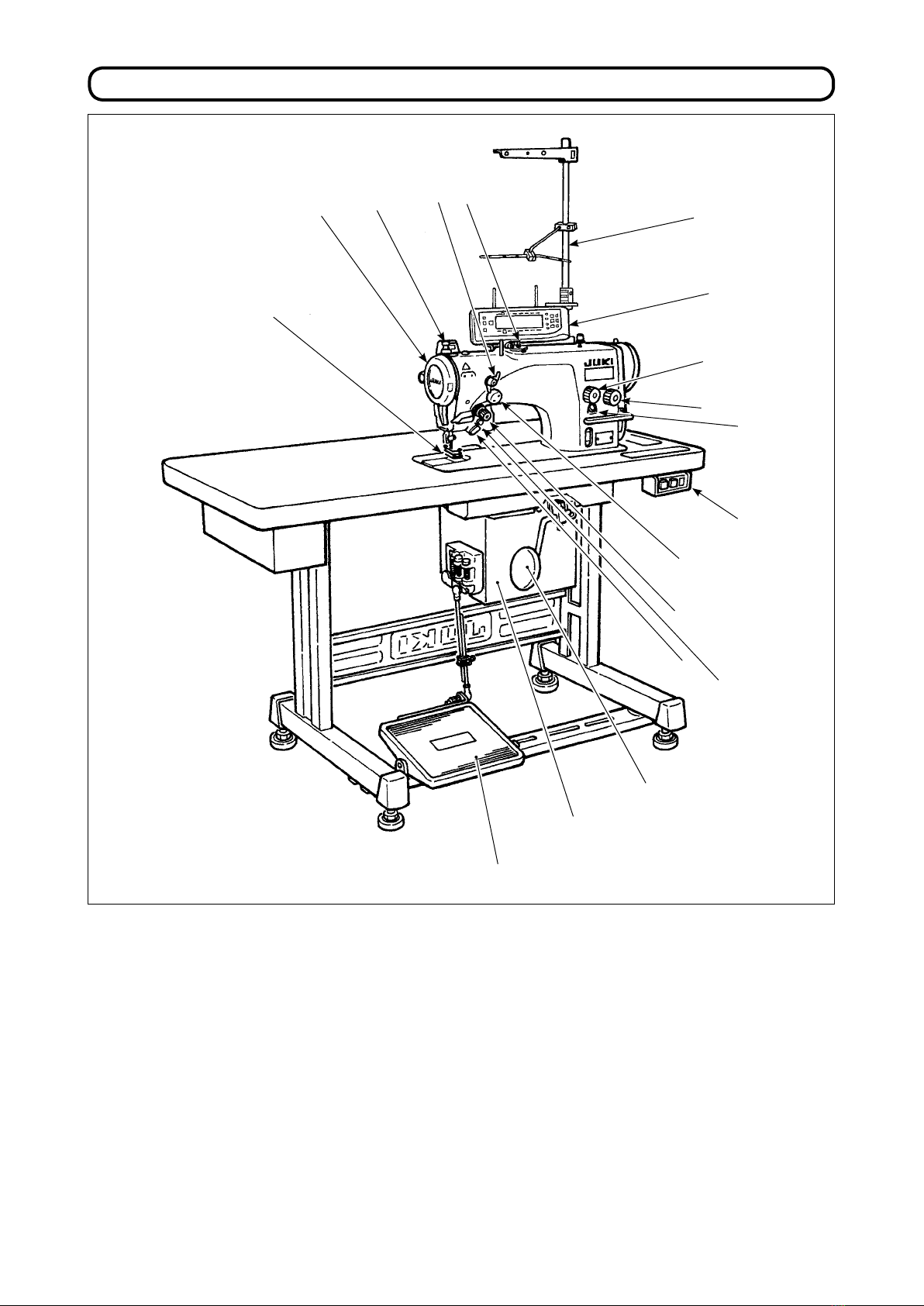
1. NAME oF EACH CoMPoNENT .................................................................................................. 1
2. SPECIFICATIoNS......................................................................................................................... 2
2-1. Specications of the machine head ..................................................................................................2
2-2. Specications of the electrical box ...................................................................................................2
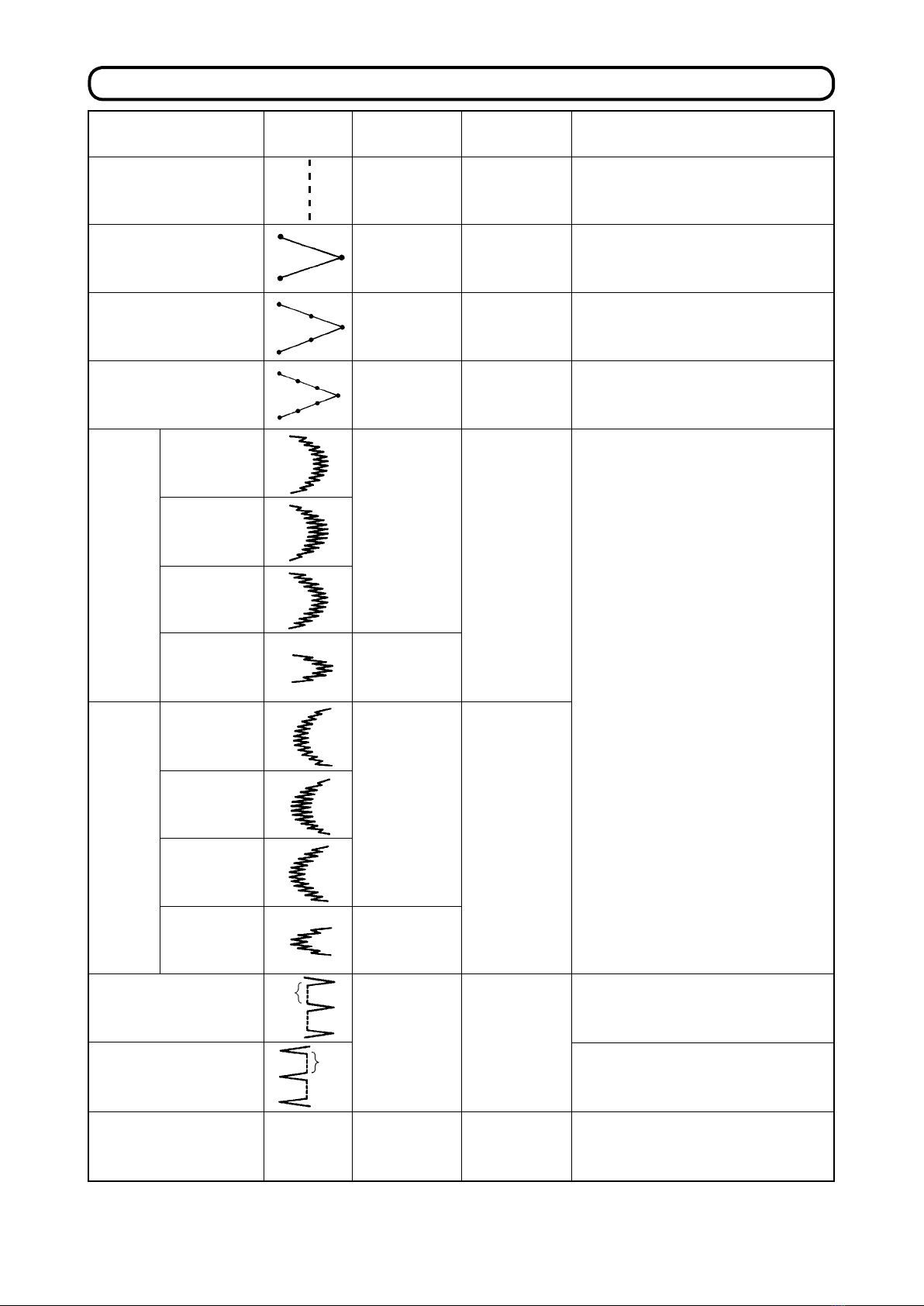
3. STITCH PATTErN TABLE ........................................................................................................... 3
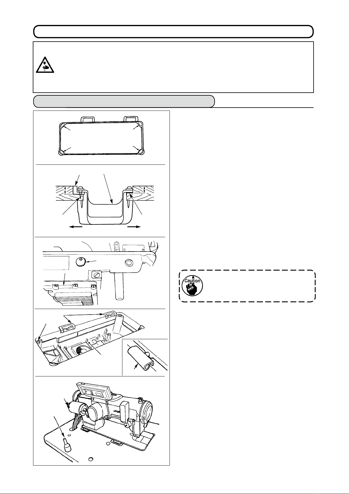
4. INSTALLATIoN............................................................................................................................. 4
4-1. Installation of the sewing machine head ..........................................................................................4
4-2. Removing the needle bar stopper .....................................................................................................5
4-3. Attaching the knee-lifter .....................................................................................................................5
4-4. Adjusting the height of the knee lifter...............................................................................................5
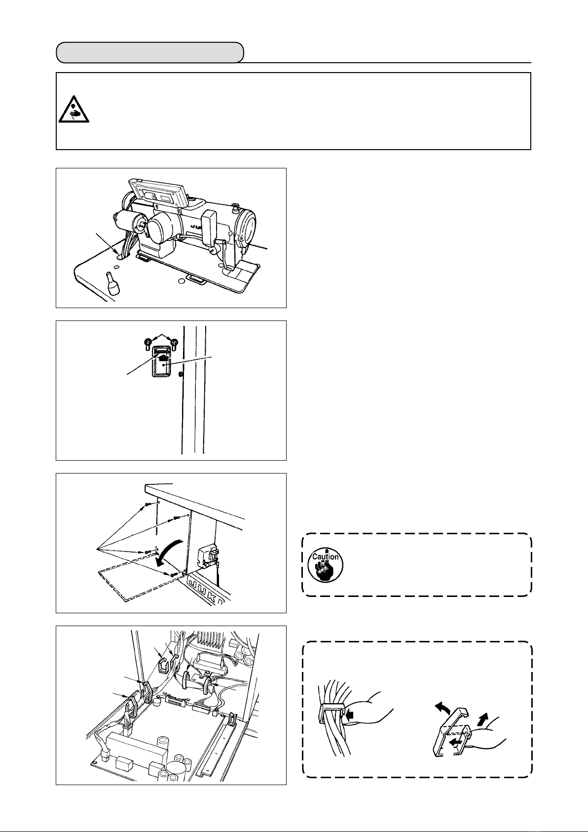
4-5. Installing the electrical box ................................................................................................................6
4-6. Connecting the power switch cord (Japan and general export area) ............................................6
4-7. Installing the operation panel (IT-100D) ............................................................................................ 6
4-8. Connecting the cords .........................................................................................................................7
(1) Preparation of wiring ........................................................................................................................................ 7
(2) Connecting the connectors............................................................................................................................... 8
4-9. Attaching the connecting rod .......................................................................................................... 11
4-10. Adjustment of the pedal ................................................................................................................. 11
4-11. Installing the thread stand.............................................................................................................. 12
4-12. Installing the bird’s nest prevention (CB) type sewing machine................................................12
4-13. Lubrication (LZ-2290A-SS • A-SU (-7) )..........................................................................................13
4-14. Test run ............................................................................................................................................14
(1) Turn ON the power......................................................................................................................................... 14
(2) How to operate the pedal ............................................................................................................................... 14
5. PrEPArATIoN BEForE SEWING ........................................................................................... 15
5-1. Inserting the needle .........................................................................................................................15
5-2. Removing the bobbin case ..............................................................................................................15
5-3. Winding the bobbin thread...............................................................................................................15
5-4. Placing the bobbin case and the bobbin ........................................................................................16
5-5. Threading the machine head ...........................................................................................................17
5-6. Adjusting the stitch length ...............................................................................................................17
5-7. Adjusting the condensation stitching .............................................................................................17
6. HoW To uSE THE oPErATIoN PANEL .................................................................................. 18
6-1. Names and functions of the respective sections...........................................................................18
6-2. Before setting the pattern ................................................................................................................20
(1) Limitation of the max. zigzag width ................................................................................................................ 20
(2) Setting the reference of stitch base line ......................................................................................................... 22
6-3. Basic screen .....................................................................................................................................23
6-4. List of the display pictographs of each screen..............................................................................24
6-5. Setting the sewing pattern ...............................................................................................................35
(1) Selecting the zigzag pattern .......................................................................................................................... 35
6-6. Setting of the sewing shape.............................................................................................................37
(1) 2-step zigzag, 3-step zigzag and 4-step zigzag stitch.................................................................................... 37
(2) Scallop stitching ............................................................................................................................................. 38
(3) Blind stitch sewing.......................................................................................................................................... 40
(4) Custom pattern stitching................................................................................................................................. 41
6-7. Reverse feed stitching......................................................................................................................42
(1) Standard condensation .................................................................................................................................. 43
(2) 2-point condensation ...................................................................................................................................... 44
(3) Condensation custom..................................................................................................................................... 46
(4) Comparison table of the reverse stitch of each shape ................................................................................... 47
6-8. Selection of the kind of stitching.....................................................................................................48
(1) Overlapped stitching....................................................................................................................................... 48
(2) Programmed stitching .................................................................................................................................... 48
6-9. Custom pattern..................................................................................................................................50
(1) Custom pattern setting ................................................................................................................................... 50
(2) New creation of the custom pattern ............................................................................................................... 51
(3) Custom pattern edit ........................................................................................................................................ 52
(4) Registration, copy and deletion of the custom pattern ................................................................................... 52
6-10. Condensation Custom....................................................................................................................54
(1) Condensation custom setting ......................................................................................................................... 54
(2) Condensation custom edit.............................................................................................................................. 55
6-11. Pattern stitching ..............................................................................................................................56
(1) Setting the pattern stitching............................................................................................................................ 56
(2) Registering the pattern stitching..................................................................................................................... 57
(3) Copy and deletion of the pattern stitching ...................................................................................................... 58

ii
6-12. Continuous stitching ......................................................................................................................59
(1) New creation of the continuous stitching........................................................................................................ 60
(2) Continuous stitching edit ................................................................................................................................ 60
(3) Copy and deletion of the continuous stitching................................................................................................ 62
6-13. Cycle stitching.................................................................................................................................63
(1) New creation of the cycle stitching ................................................................................................................. 63
(2) Cycle stitching edit ......................................................................................................................................... 63
(3) Copy and deletion of the cycle stitching ......................................................................................................... 65
(4) Teaching ......................................................................................................................................................... 66
(5) Performing the constant-dimension stitching using the cycle stitching .......................................................... 67
6-14. Counter ............................................................................................................................................67
(1) Thread trimming counter ................................................................................................................................ 67
(2) Bobbin thread counter .................................................................................................................................... 67
6-15. Information ......................................................................................................................................68
(1) Sewing common data..................................................................................................................................... 69
(2) Sewing management information................................................................................................................... 71
(3) Communication mode .................................................................................................................................... 74
6-16. Setting for functions .....................................................................................................................78
(1) How to change over to the function setting mode .......................................................................................... 78
(2) Function setting list ........................................................................................................................................ 81
(3) Detailed explanation of selection of functions ................................................................................................ 85
6-17. External interface .......................................................................................................................... 91
(1) Media slot....................................................................................................................................................... 91
(2) Ethernet port .................................................................................................................................................. 91
(3) RS-232C port ................................................................................................................................................. 91
(4) General input port (Production control switch connecting connector)............................................................ 91
6-18. Setting the maximum sewing speed ...........................................................................................92
6-19. Panel memory switch setting.......................................................................................................92
7. SEWING ...................................................................................................................................... 94
7-1. Adjusting the thread tension............................................................................................................94
7-2. Adjusting the pressure of the presser foot.....................................................................................95
7-3. One-touch type reverse feed stitching mechanism.......................................................................95
7-4. Hand switch .......................................................................................................................................97
8. STANDARD ADJUSTMENT ....................................................................................................... 98
8-1. Adjusting the amount of oil in the hook (LZ-2290A-SS • A-SU (-7) ).............................................98
8-2. Adjusting the amount of lubricating to face plate section (LZ-2290A-SS•A-SU(-7))...................98
8-3. Adjusting the height of the presser bar ..........................................................................................99
8-4. Adjusting the micro-lifting mechanism of the presser foot ..........................................................99
8-5. Height and inclination of the feed dog............................................................................................99
8-6. Hook adjusting mode......................................................................................................................100
8-7. Attaching / removing the hook.......................................................................................................102
8-8. Adjusting height of the needle bar ................................................................................................103
8-9. Adjusting the needle-to-hook timing and the needle guard........................................................103
8-10. Adjusting the stop position of the needle...................................................................................104
8-11. Adjusting the thread trimmer .......................................................................................................104
8-12. Adjusting the needle thread feeding device (Thread trimmer type only) ................................105
8-13. Adjusting the bird's nest prevention (CB) type wiper................................................................106
8-14. Replacing procedure of the bird’s nest prevention (CB) type presser knife...........................107
9. MAINTENANCE ........................................................................................................................ 108
(1) Replacing the power fuse............................................................................................................................. 108
(2) Adjusting the contrast of the operation panel display................................................................................... 108
(3) Draining (Bird’s nest prevention (CB) type only) .......................................................................................... 109
(4) Cleaning the dust bag (Bird’s nest prevention (CB) type only)..................................................................... 109
(5) Cleaning the cooling fan installed on the under cover.................................................................................. 109
(6) Cleaning the hook section ............................................................................................................................ 110
(7) Cleaning the rear cover of the control box ................................................................................................... 110
(8) Cleaning the operation panel screen ........................................................................................................... 110
(9) Replacing procedure of the hook shaft oil wick ............................................................................................ 110
(10) USB port......................................................................................................................................................111
10. AT A TIME LIKE THIS !........................................................................................................... 112
11. Error DISPLAY.................................................................................................................... 113
11–1. Error code list (Error display in panel) ....................................................................................... 114
12. TrouBLES AND CorrECTIVE MEASurES ...................................................................... 117

– 1 –
1. NAME oF EACH CoMPoNENT
1Needle thread draw-out device (LZ-2290A(U)-7)
2Wiper switch (WB,CB type)
3Thread take-up cover
4Finger guard
5Thread tension controller (Rotary tension)
6Electrical box
7Pedal
8Knee lifter lever
9Power switch
4
32!4
!3
!5
!6
!2
!1
!7
o
q
t
!0
i
y
u
!8
!0 Hand switch
!1 Stitch length dial
!2 Condensation dial
!3 Operation panel
!4 Bobbin winder
!5 Tension controller No. 1 (Pre-tension)
!6 Thread stand
!7 Oil supply opening
!8 Mirror inversion switch

– 2 –
2. SPECIFICATIoNS
2-1. Specications of the machine head
* 1. The max. sewing speed is limited by the amount of zigzag width per stitch.
Up to 4 mm : 5,000 sti/min (LZ-2290A-SU : 4,500 sti/min, LZ-2290A-DS •A-DU (-7) : 4,000 sti/min),
up to 5 mm : 4,000 sti/min, up to 6 mm : 3,500 sti/min, up to 8 mm : 3,000 sti/min
•Properly set the number of revolution in accordance with the product to be sewn and process.
* 2. Max. zigzag width is limited to 8 mm at the time of standard delivery.
2-2. Specications of the electrical box
Supply voltage Single phase 220V / 230V / 240V
Frequency 50 Hz/60 Hz
Rated currency 4.3A / 4.2A / 4.0A
Operating environment
Temperature : 0 to 40˚C Humidity : 90% or less
Supply voltage Single phase 200V / 220V / 240V 3-phase 200V / 220V / 240V
Frequency 50 Hz / 60 Hz
Rated currency 4.6A / 4.3A / 4.0A 3.0A / 2.7A / 2.3A
Operating environment
Temperature : 0 to 40˚C Humidity : 90% or less
Supply voltage Single phase 100V / 110V / 120V 3-phase 200V / 220V / 240V
Frequency 50 Hz / 60 Hz
Rated currency 8.0A / 7.5A / 7.0A 3.0A / 2.7A / 2.3A
Operating environment
Temperature : 0 to 40˚C Humidity : 90% or less
■For JUS
■For general export
■For CE
( )
Minute-quantity
lubricating type
Model LZ-2290A-SS LZ-2290A-SS-7 LZ-2290A-SU LZ-2290A-SU-7
Application Light-weight materials to medium-weight materials
Max. sewing speed 5,000 sti/min (*1) 4,500 sti/min (*1)
Max. zigzag width 10 mm (*2)
Max. feed pitch 5 mm (stepless ne adjustment) 2.5 mm (stepless ne adjustment)
Stitch pattern 8 kinds 14 patterns (custom pattern : up to 500 stitches, 20 kinds can be stored.)
Needle SCHMETZ 438, ORGAN DPX5 : #65 to #90
Oil used JUKI New Defrix Oil No. 1
Thread trimmer Without With Without With
Feed method Standard feed Material slippage prevention
Noise - Equivalent continuous emission sound pressure level (LpA) at the workstation :
A-weighted value of 80.0 dB; (Includes KpA = 2.5 dB); according to ISO 10821- C.6.2 -ISO
11204 GR2 at 4,500 sti/min.
Model
(Dry-head type)
LZ-2290A-DS LZ-2290A-DS-7 LZ-2290A-DU LZ-2290A-DU-7
Application Light-weight materials to medium-weight materials
Max. sewing speed 4,000 sti/min (*1)
Max. zigzag width 10 mm (*2)
Max. feed pitch 5 mm (stepless ne adjustment) 2.5 mm (stepless ne adjustment)
Stitch pattern 8 kinds 14 patterns (custom pattern : up to 500 stitches, 20 kinds can be stored.)
Needle SCHMETZ 438, ORGAN DPX5 : #65 to #90
Thread trimmer Without With Without With
Feed method Standard feed Material slippage prevention
Noise - Equivalent continuous emission sound pressure level (LpA) at the workstation :
A-weighted value of 80.0 dB; (Includes KpA = 2.5 dB); according to ISO 10821- C.6.2 -ISO
11204 GR2 at 4,500 sti/min.

– 3 –
1
2
4
6
24
12
24
12
2+a
500
—
10
10
10
10
10
10
10—
Name of pattern Stitch pat-
tern
3. STITCH PATTErN TABLE
Straight stitch
2-step zigzag stitch
3-step zigzag stitch
4-step zigzag stitch
Scallop
(right)
Scallop
(left)
Blind stitch (right)
Blind stitch (left)
Custom pattern
Standard
scallop
Crescent
scallop
Equal-width
scallop
Equal-width
scallop
Standard
scallop
Crescent
scallop
Equal-width
scallop
Equal-width
scallop
Number of stitches
for pattern
Remarks
Max.zigzag width
a
a

– 4 –
■ Installing the under cover
1) The under cover should rest on the four corners
of the machine table groove.
2) Fix two rubber seats 1on side A(operator’s
side) using nails 2as illustrated above. Fix two
cushion seats 3on side B(hinged side) using a
rubber-based adhesive. Then place under cover
4 on the xed seats.
3) Remove air vent cap 5attached to the machine
bed. (Be sure to attach cap 5when transporting
the machine head in the state that the machine
head is removed from the machine table.)
If the sewing machine is operated with-
out removing air vent cap 5, oil leakage
from gear box portion 7 may occur.
4) Fit hinge 1into the opening in the machine bed,
and t the machine head to table rubber hinge 8
before placing the machine head on cushions 3
on the four corners.
5) Attach head support rod 6to the machine table.
(However, this step is not necessary for the ma-
chine with AK 9device.)
23.5 mm 19.5 mm
14
AB
4. INSTALLATIoN
4-1. Installation of the sewing machine head
WArNING :
• Perform the installation of the sewing machine by the technical personnel who have been trained.
• To prevent personal injury, ask our dealer or the electrician for electric wiring.
• Be sure to perform the work with two persons or more when transporting the sewing machine and use a
lorry when moving it.
• To prevent personal injury caused by abrupt start of the sewing machine, do not connect the power plug
until the set-up of the sewing machine is completed.
• Be sure to earth the ground wire to prevent personal injury caused by leak.
• Be sure to attach safety protection cover, nger guard, etc.
3
2
5
7
1
3
1
3
1
4
3
8
6
9

– 5 –
4-4. Adjusting the height of the knee lifter
1) The standard height of the presser foot lifted us-
ing the knee lifter is 10 mm.
2) You can adjust the presser foot lift using knee
lifter adjust screw 1.
Do not operate the sewing machine in
the state that presser foot 3 is lifted by
10 mm or more since needle bar 2 and
presser foot 3, or wiper 4 and presser
foot 3 come in contact with each other.
4-2. Removing the needle bar stopper
Remove needle bar stopper 1for transportation.
Keep the needle bar stopper which has
been removed, and install this needle
bar stopper when transporting the sew-
ing machine. The needle bar stopper
may be cut when it is strongly drawn
out. Slightly move the needle bar to
the right or left and slowly draw out the
needle bar stopper.
4-3. Attaching the knee-lifter
Insert knee lifter pad 1into attaching hole 2and
tighten it with bolt 3.
* Adjust the position of knee lifter pad 1to a con-
venient place. For the reference dimension, the
position is 220 mm from the bottom face of table.
1
1
23
220 mm
2
3
4
1

– 6 –
4-6. Connecting the power switch cord
(Japan and general export area)
1) Loosen screw 1located on the side of the power
switch supplied as accessories and remove the
power switch cover.
2) Connecting the input power cord of electrical box
¡When the input power cord of electrical box is 4P
Put 4P cord from hole A of the power switch and
securely x green/yellow cord to 5, white cord to 2,
black cord to 3and red cord to 4with screws.
¡When the input power cord of electrical box is 3P
Put 3P cord from hole A of the power switch and
securely x green/yellow cord to 5, brown cord to
2and sky blue cord to 3with screws.
3) Connecting the power cable supplied as accessories
¡In case of 3-phase power cable
Put power cable from hole B of the power switch, and
securely x green/yellow cord to 9, white cord to 6,
black cord to 7and red cord to 8with screws.
¡In case of single phase power cable
Put power cable from hole B of the power switch,
and securely x green/yellow cord to 9and other
cords to 6and 7with screws. 8is not used.
4) Installing the power switch cover
Securely tighten screw 1located on the side of
the power switch.
4-7. Installing the operation panel (IT-100D)
1) Install operation panel 1on the machine head
using screws 3which have been assembled to
panel installing bracket 2.
4-5. Installing the electrical box
Install the electrical box on the under side of the
table using round-head bolts 1, plain washers 2,
spring washers 3and nuts 4supplied with the ma-
chine at the location illustrated, and using bolt having
hexagonal indentation on the head 5, spring washer
6and plain washer 7supplied with the machine at
the location illustrated.
Do not disassemble the operation
panel to prevent it from breakage.
1
6
9
B
7
8
3
4
5
2
1
2
5
4
3
6
7
A
1
2
3
3
3

– 7 –
(1) Preparation of wiring
1) Pass the cords coming from the machine head to
the underside of the table through hole A in the
table.
2) Loosen screws D and lift cord presser plate C of
cord passing hole B located on the front cover to
the top and temporarily tighten the plate.
3) Remove four screws E xing the rear cover of
the electrical box. When opening the rear cover,
pressing it with your hands, slowly open it by ap-
proximately 90˚ until it stops as illustrated.
Be sure to lend your hand to the rear
cover in order not to let the rear cover
fall. In addition, do not apply force to the
rear cover opened.
4) Remove the locks of cord clamps a, b, c, d, e, and f.
C
d
ab
E
B
D
e
f
c
4-8. Connecting the cords
WArNING :
• To prevent personal injury caused by abrupt start of the sewing machine, carry out the work after turning
OFF the power switch and a lapse of 5 minutes or more.
• To prevent damage of device caused by maloperation and wrong specications, be sure to connect all the
corresponding connectors to the specied places.
• To prevent personal injury caused by maloperation, be sure to lock the connector with lock.
• As for the details of handling respective devices, read carefully the Instruction Manuals supplied with the
devices before handling the devices.
Slowly
How to remove the cord clamp
1 Lightly pressing
2 Pull down the clamp.
3 The clamp goes up.
2
3
1
1
* See P.11 for how to lock the cord clamp.
A

– 8 –
Connect cords in the following order.
5) Insert yellow/green earth cord 1coming from
the machine head inside the electrical box
through front cover through hole B, and pass it
through cord clamp “b” as illustrated and tighten
it with screw at the position 2in the illustration.
6) Insert white square connector 9P black cord 3
coming from the machine head inside the electri-
cal box through front cover through hole B, and
insert it into connector CN38 4of the circuit
board attached to the front cover.
7) Insert white connector 4P black cord 5coming
from the machine head inside the electrical box
through front cover through hole B, and insert it
into connector CN21 6of the circuit board at-
tached to the front cover.
8) Insert white connector 26P cord 7coming
from the operation panel inside the electrical
box through front cover through hole B, pass it
through cord clamps “b”, “c” and “d”, insert it into
connector CN34 8, and lock it.
2
b
B
1
3
B
4
5
6
(2) Connecting the connectors
• Each connector has the inserting direction. Check the direction and securely insert it. (In
case of the type with lock, insert up to the lock.)
• If the connector is forcibly inserted, trouble or accident will be caused.
• Never pull out the connectors inserted at the time of delivery.
• The sewing machine fails to work if the connectors are not properly inserted. Not only the
problem such as the error warning or the like but also breakage of the sewing machine or
electrical box will occur.
B
u
i
c
b
d
B

– 9 –
9) Insert black connector 4P white cord 9coming
from the machine head inside the electrical box
through front cover through hole B, and insert it
into connector CN31 !0.
10) Insert gray round connector 7P cord !1 com-
ing from the machine head inside the electrical
box through front cover through hole B, pass it
through cord clamp “a”, and insert it into connec-
tor CN30 !2.
11) Insert white connector 12P cord !3 coming from
the machine head inside the electrical box through
front cover through hole B, pass it through cord
clamps “b”, “c”, “d” and “g”, and insert it into con-
nector CN53 !4.
Close cord clamps “b”, “c” and “d”.
12) Insert white connector 6P three cords !5 com-
ing from the machine head inside the electrical
box through front cover through hole B, pass it
through cord clamps “a” and “e”, and insert it into
connector CN54 !6.
13) Insert white connector 10P cord !7 and blue
connector 2P cord !8 coming from the machine
head inside the electrical box through front cover
through hole B, pass them through cord clamps
“a”, “e” and “f”, and insert the white 10P into con-
nector CN51 !9 and the blue 2P into CN46 @0.
Close cord clamps “a”, “e” and “f”.
!4
!3
!5
!6
!8
!7
@0
!9
e
g
fe
a
The blue 2P connector is attached only
for the machine with thread trimmer.
c
b
d
a
o
!0
b
c
!1
!2
a

– 10 –
When the Auto-lifter (AK121) is used :
14) Insert white connector 2P cord
@
1coming from
the machine head inside the electrical box
through front cover through hole B, pass it
through cord clamps “a”, “e” and “f”, and insert it
into connector CN40 @2.
When the bird’s nest prevention device is used
(CB type)
15) Insert white small connector 6P cord @3 com-
ing from the machine head inside the electrical
box through front cover through hole B, pass
it through cord clamps “a” and “e”, and insert it
into connector CN52 @4.
When foot pedal for standing work (PK70 or 71) is
used :
16) Insert black connector 12P cord @5 inside the
electrical box through front cover through hole
B coming from the foot pedal for standing work,
pass it through cord clamps “b” and “c”, and
insert it into connector CN32 @6.
17) Connect white connector 2P of cord @7 sup-
plied as accessories to which red connector 2P
and white connector 2P are attached to white
connector 2P @8 of under cover of the machine
head.
Fix omega lock @9 supplied as accessories with
the neighboring cords and cord @7 as shown in
the gure.
18) Insert red connector 2P side of cord @7 supplied
as accessories to which red connector 2P and
white connector 2P are attached inside the elec-
trical box through front cover through hole, and
insert it into red connector CN25 #0.
@1
@2
@4
@3
@6 @5
f
ea
a
e
b
c
@8
@7 @9
#0
@7
Change the setting of function setting No.
23 from “0” to “1” after completing all set-up
procedure. For the details, see p.78 and p.81.

– 11 –
■ Installing the connecting rod
1) Move pedal 3to the right or left as illustrated by
the arrows so that motor control lever 1and con-
necting rod 2are straightened.
■ Adjusting the pedal angle
1) The pedal tilt can be freely adjusted by changing
the length of the connecting rod.
2) Loosen adjust screw 4, and adjust the length of
connecting rod 2.
When the insertion of the connector is completed,
lock the cord clamps.
qTake care so that the cord is not caught between
the rear cover and the electrical box main body,
close the rear cover while pressing section A on
the lower side of the rear cover, and tighten four
screws 1.
wPress down cord presser plate C of cord through
hole B of the front cover, press the cord, and
tighten screws 2.
1
2
3
A
B
C
4
3
4
B
A
1
2
Clamp
1
4
3
2
4 Lightly press the corner of clamp.
(Cord clamp is locked with a click.)
How to lock the cord clamp
4-9. Attaching the connecting rod
1) Fix connecting rod 1to installing hole Bof pedal
lever 2with nut 3.
2) Installing connecting rod 1to installing hole A
will lengthen the pedal depressing stroke, and the
pedal operation at a medium speed will be easier.
4-10. Adjustment of the pedal

– 12 –
1) Punch dots on the positions of the setscrews of
solenoid valve (asm.) and regulator (asm.) on the
bottom surface of the machine table.
Besides, awling is performed on JUKI genuine
table.
2) Fix solenoid valve (asm.) 1with wood screw 2
supplied with the sewing machine as accesso-
ries.
3) Fix regulator (total asm.) 3with wood screw 4
supplied with the sewing machine as accesso-
ries.
4) Connect ø6 and ø8 hoses attached to regulator
(total asm.) 3to the respective solenoid valves.
5) Insert dust bag 5into the top end of hose 9for
dust bag and x it with band 6supplied with the
sewing machine as accessories.
4-12. Installing the bird’s nest prevention (CB) type sewing machine
1
2
4
3
6
5
9
5
9
4-11. Installing the thread stand
1) Assemble the thread stand unit, and insert it in
the hole in the machine table.
2) Tighten locknut 1 to x the thread stand.
3) For ceiling wiring, pass the power cord through
spool rest rod 2.
(bottom surface of the machine table)
75
291 34
233
106107
(mm)
1
2

– 13 –
9) Connect the air pipe !2 and set the air pressure
to 0.6 MPa.
Fill the oil tank with oil for hook lubrication before
operating the sewing machine.
1) Remove oil hole cap 1 and ll the oil tank with
JUKI New Defrix Oil No. 1 using the oiler supplied
with the machine.
2) Fill the oil tank with oil up to the place where the
top of oil amount indicating rod 3aligns with
the upper engraved line of oil amount indicating
window 2. If the oil is lled excessively, it will
leak from the air vent hole in the oil tank or proper
lubrication will be not performed. So, be careful.
3) When you operate the sewing machine, rell oil if
the top end of oil amount indicating rod 3comes
down to the lower engraved marker line of oil
amount indicating window 2.
6) Adjust solenoid valve cord (asm.) 7to the so-
lenoid valve and the hot marker of the cord, and
connect it.
Connect 6P connector !0!1 to CM52 connector
inside the electrical box.(Refer to “When the bird’
s nest prevention device is used, p. 10".)
7) Connect air hose ø4 coming from the machine
head to the solenoid valve section and air hose
ø8 to the dust bag suction port respectively.
8) Fix the solenoid valve and the air hose on the
table with staple 8supplied as accessories.
3
2
2
1
Upper engraved
marker line
4-13. Lubrication (LZ-2290A-SS • A-SU (-7) )
WArNING :
1. Do not connect the power plug until the lubrication has been completed so as to prevent ac-
cidents due to abrupt start of the sewing machine,
2. To prevent the occurrence of an inammation or rash, immediately wash the related portions if
oil adheres to your eyes or other parts of your body.
3. If oil is mistakenly swallowed, diarrhea or vomitting may occur. Put oil in a place where children
cannot reach.
1. Fix the staple to such an extent that
the air hose is not crushed.
2. Determine the position of the staple
so that the cord and the air hose do
not hang from the table.
• When you use a new sewing ma-
chine or a sewing machine after an
extended period of disuse, run your
machine at 3,000 to 3,500 sti/min for
the purpose of break-in.
• For the oil for hook lubrication, pur-
chase JUKI New Defrix Oil No. 1 (Part
No. : MDFRX1600C0).
Lower engraved
marker line
7
!1
ø 8
ø 4
!0
!1
!0
8
!2

– 14 –
(2) How to operate the pedal
The pedal is operated in four stages.
1) Lightly depress the front part of the pedal for low-
speed operation B.
2) Further depress the front part of the pedal for
high-speed operation A. (Note that the sew-
ing machine will enter the high-speed operation
mode after the completion of reverse feed stitch-
ing if the automatic reverse feed stitching function
is specied with the corresponding switch.)
3) Bring the pedal back to its neutral position, and
the sewing machine will stop running C.
(The needle stops in the highest / lowest posi-
tion.)
4) Strongly depress the back part of the pedal, and
the thread trimmer will be actuated E.
Lightly depress the back part of the pedal, and
the presser foot will go up D. Further depress the
back part of the pedal, and the thread trimmer will
be actuated.
A
B
D
E
C
4-14. Test run
(1) Turn ON the power
1) When the needle bar is in its UP position, zigzag origin detection is performed.
2) When the needle bar is in the position other than UP position :
Display as shown in the gure below appears. Turn the handwheel to bring the needle bar to needle UP
position and the display changes to the next screen. Then the needle moves left and right, and zigzag
origin detection is performed.
WArNING :
• Check again the power voltage before connecting the power cord.
• Check that the power switch is turned OFF and connect the power cord to the power receptacle.
• Be sure to connect the earth wire.
• In case where the buzzer keeps beeping immediately after turning ON the power, there is a possi-
bility of the wrong connection of cord or wrong power voltage. Turn OFF the power.
h

– 15 –
1) Insert the bobbin deep into the bobbin winder
spindle 5until it will go no further.
2) Pass the bobbin thread pulled out from the spool
rested on the right side of the thread stand following
the order from 1 as shown in the gure on the left.
Then, wind the end of the bobbin thread on the bob-
bin several times.
3)
Press the bobbin winder adjusting plate 6in the
direction of A and start the sewing machine. The bob-
bin rotates in the direction of C and the bobbin thread
is wound up. The bobbin winder spindle 5will auto-
matically stop as soon as the winding is nished.
4) Remove the bobbin and cut the bobbin thread with
the thread cut retainer 8.
5)
To adjust the winding amount of the bobbin thread, loosen
setscrew
7
and move bobbin winder adjusting plate
6
to the direction of A or B. Then, tighten setscrew
7
.
To the direction A : The amount is decreased.
To the direction B : The amount is increased.
1) Turn the handwheel by hand to raise the needle
to its highest position.
2) Loosen the needle clamp screw 2. Hold the nee-
dle 1so that the long groove Bon the needle is
facing exactly toward you.
3) Insert the needle deep into the hole of the needle
bar in the direction of the arrow until it will go no
further.
4) Securely tighten the screw 2.
5) Conrm that the long groove Bon the needle
faces toward you.
5. PrEPArATIoN BEForE SEWING
WArNING :
To protect against possible personal injury due to abrupt start of the machine, be sure to start the
following work after turning the power off and ascertaining that the motor is at rest.
5-1. Inserting the needle
WArNING :
To protect against possible personal injury due to abrupt start of the machine, be sure to start the
following work after turning the power off and ascertaining that the motor is at rest.
5-2. Removing the bobbin case
1) Turn the handwheel by hand to raise the needle
to its highest position.
2) Raise bobbin case latch 1and remove the bob-
bin case.
5-3. Winding the bobbin thread
WArNING :
To protect against possible personal injury due to abrupt start of the machine, be sure to start the
following work after turning the power off and ascertaining that the motor is at rest.
1
2
BA
1
3
2
1
A
C
B
76
58

– 16 –
1) Turn the handwheel by hand to raise the needle
to its highest position.
2) Take a bobbin by your right hand with the thread
drawn out about 5 cm from the thread end of the
bobbin and place it into the bobbin case as illus-
trated.
3)
Thread the bobbin case in the order of the numbers
and pull it out through the thread path as illustrated.
The bobbin rotates in the bobbin case in the direction
shown by arrow when bobbin thread is drawn.
4) Raise bobbin case latch 1and hold it between
your two ngers as shown in the gure on the left.
5) Insert the bobbin case into the sewing hook shaft
as far as it will go by putting your hand from the
under cover of the inner hook. (Click sounds.)
6) Release the bobbin case latch to let it steadily
rest in the closing position.
■How to use the bobbin case thread hole
1) Use hole A mainly for zigzag stitches other than
2-step zigzag stitch and scallop zigzag stitch.
2) Use hole B mainly for 2-step zigzag stitch and
scallop zigzag stitch.
6) In case that the bobbin thread is not wound
evenly on the bobbin, loosen the nut 4and turn
the bobbin thread tension to adjust the height of
the thread tension disk 2.
• It is the standard that the center of the bobbin is
as high as the center of the thread tension disk.
• Move the position of the thread tension disk 2to
the direction A as shown in the gure on the left
when the winding amount of the bobbin thread on
the lower part of the bobbin is excessive and to
the direction B as shown in the gure on the left
when the winding amount of the bobbin thread on
the upper part of the bobbin is excessive.
After the adjustment, tighten the nut 4.
7) Turn the thread tension nut 3to adjust the ten-
sion of the bobbin thread winder.
1
2
3
1
(Threading)
A
B
There may be a case where several stitches at the start of sewing are difcult to be knotted
when thread trimmer is used with thin lament thread such as (#50, #60 or #80) using hole B.
At this time, use the other hole or perform the sewing starting from the right.
WArNING :
To protect against possible personal injury due to abrupt start of the machine, be sure to start the
following work after turning the power off and ascertaining that the motor is at rest.
5-4. Placing the bobbin case and the bobbin
Note 1. When winding bobbin thread, start winding
in the state that the thread between bobbin
and thread tension disk 2 is tense.
2. When winding bobbin thread in the state
that the sewing is not performed, remove
needle thread from the thread path of the
thread take-up and remove bobbin from the
hook.
A
B
2
2
2
4
2
3
1

– 17 –
5-6. Adjusting the stitch length
1) Turn the stitch length dial 1in the direction of
the arrow so that the number corresponding to
the desired stitch length meets the marker dot A
engraved on the machine arm.
2)
Numbers on the stitch length dial are calibrated in mm.
3) To perform reverse feed stitching, press down the
feed lever 2. The sewing machine performs re-
verse feed stitching as long as you keep the feed
lever held pressed. The feed lever will return to its
home position and the sewing machine will run in
the normal stitching direction when you release
the feed lever.
5-7. Adjusting the condensation stitching
Stitch length can be reduced at the start or end of
sewing. This feature is used for fastening stitch.
1) Turn condensation stitching adjusting dial 3in
the direction of the arrow mark, and adjust the de-
sired number to engraved dot Bon the machine
arm.
2)
The number of the graduation is shown in the unit of mm.
3)
Turn condensation stitching adjusting dial 3in the
direction of + to reduce the reverse feed stitch length.
Example : When stitch length dial 1is used with the
graduation of +2, the maximum adjustment value
of condensation stitching adjusting dial 3be-
comes -2. (It is possible to adjust within the range
of -2 to +2.)
Maximum feed amount is regulated to ±2 according to the gauge delivered (feed dog :
22581508). Adjustment can be performed up to the range of maximum +5 to -4 by replacing the
gauge (feed dog : 22540009).
4) Note that the graduations on the dial are mere reference. Adjust the condensation stitching while actu-
ally observing the nished seam.
A
2
1
3
B
WArNING :
To protect against possible personal injury due to abrupt start of the machine, be sure to start the
following work after turning the power off and ascertaining that the motor is at rest.
5-5. Threading the machine head
1) Turn the handwheel by hand to bring the needle to the most raised position.
2) Pass the thread in the order of the numbers as illustrated.
3) Pull out the thread about 10 cm from the needle after passing it through the needle.
1
1
2
4
3
5
6
LZ-2290A
Without thread
trimmer
LZ-2290A-7
With thread
trimmer
Turn the thread
once.
Without auxiliary
thread take-up
With auxiliary
thread take-up
This manual suits for next models
2
Table of contents
Other JUKI Sewing Machine manuals

JUKI
JUKI CP-180 User manual

JUKI
JUKI S057 User manual

JUKI
JUKI MP-G10-NC User manual

JUKI
JUKI TL-2200QVP Mini User manual

JUKI
JUKI MS-1190 User manual

JUKI
JUKI NZ-120 User manual

JUKI
JUKI LBH-1790 Series User manual

JUKI
JUKI DDL-8700-7 User manual

JUKI
JUKI PLK-J4040R User manual

JUKI
JUKI DDL-9000C-S Series User manual

JUKI
JUKI DNU-1541 User manual

JUKI
JUKI IP-310 User guide

JUKI
JUKI LZ-2290A Series User manual

JUKI
JUKI MO-623 User manual

JUKI
JUKI DLN-415 User manual

JUKI
JUKI J-350QVP User manual

JUKI
JUKI MO-734DE User manual

JUKI
JUKI MP-200NS User manual

JUKI
JUKI AMB-289/IP-420 User manual

JUKI
JUKI LU-2810 Series Quick start guide