JUKI IT-10 User manual

ENGLISH
IT-10
INSTRUCTION MANUAL

CONTENTS
1. INTROdUCTION...................................................................................... 1
2. CONNECTING THE COUNT MANUAL SwITCH ................................... 1
3. USB pORT............................................................................................... 2
4. SETTING pROCEdURE Of THE MACHINE HEAd .............................. 2
5. AdjUSTING THE MACHINE HEAd(dIRECT-dRIvE MOTOR TypE
SEwING MACHINE ONLy) ..................................................................... 3
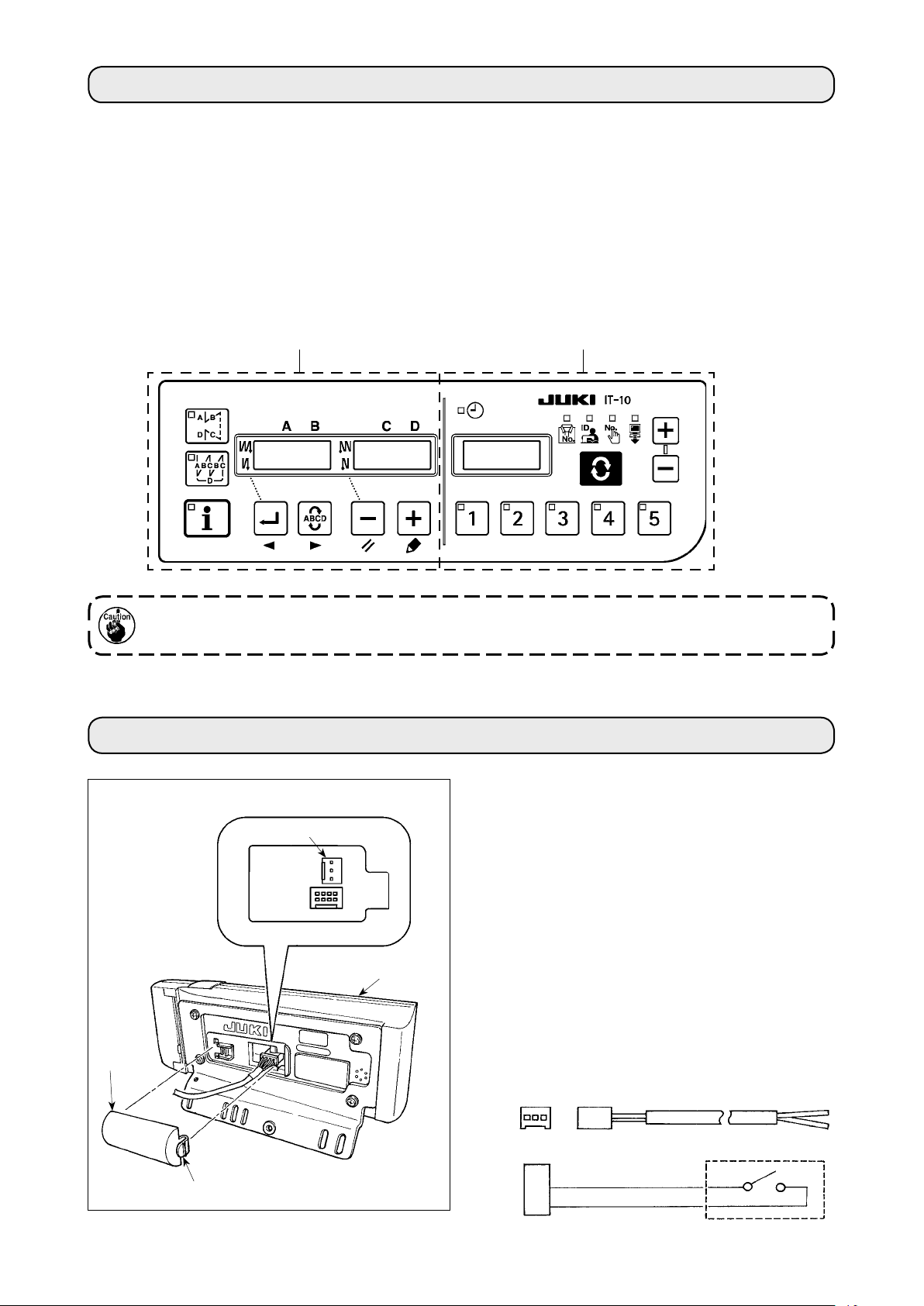
6. SEwING pATTERN SETUp BLOCk (LEfT pANEL) ............................. 4
6-1. Conguration.................................................................................................................................4
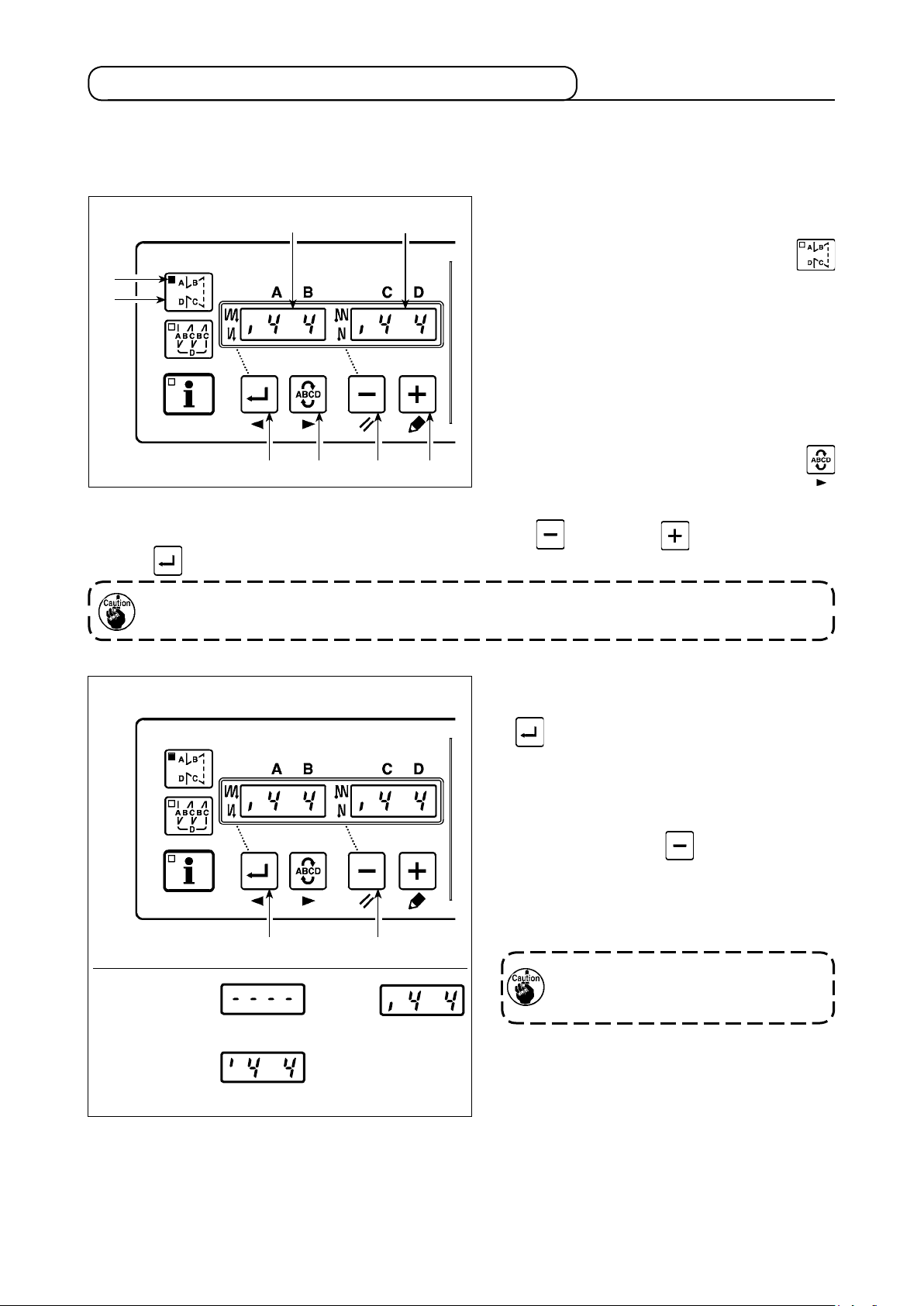
6-2. Operatingprocedureofthesewingpattern ...............................................................................5
(1) Reverse feed stitching pattern .................................................................................................... 5
(2) Overlapped stitching pattern ....................................................................................................... 6
6-3. One-touchsetting .........................................................................................................................7
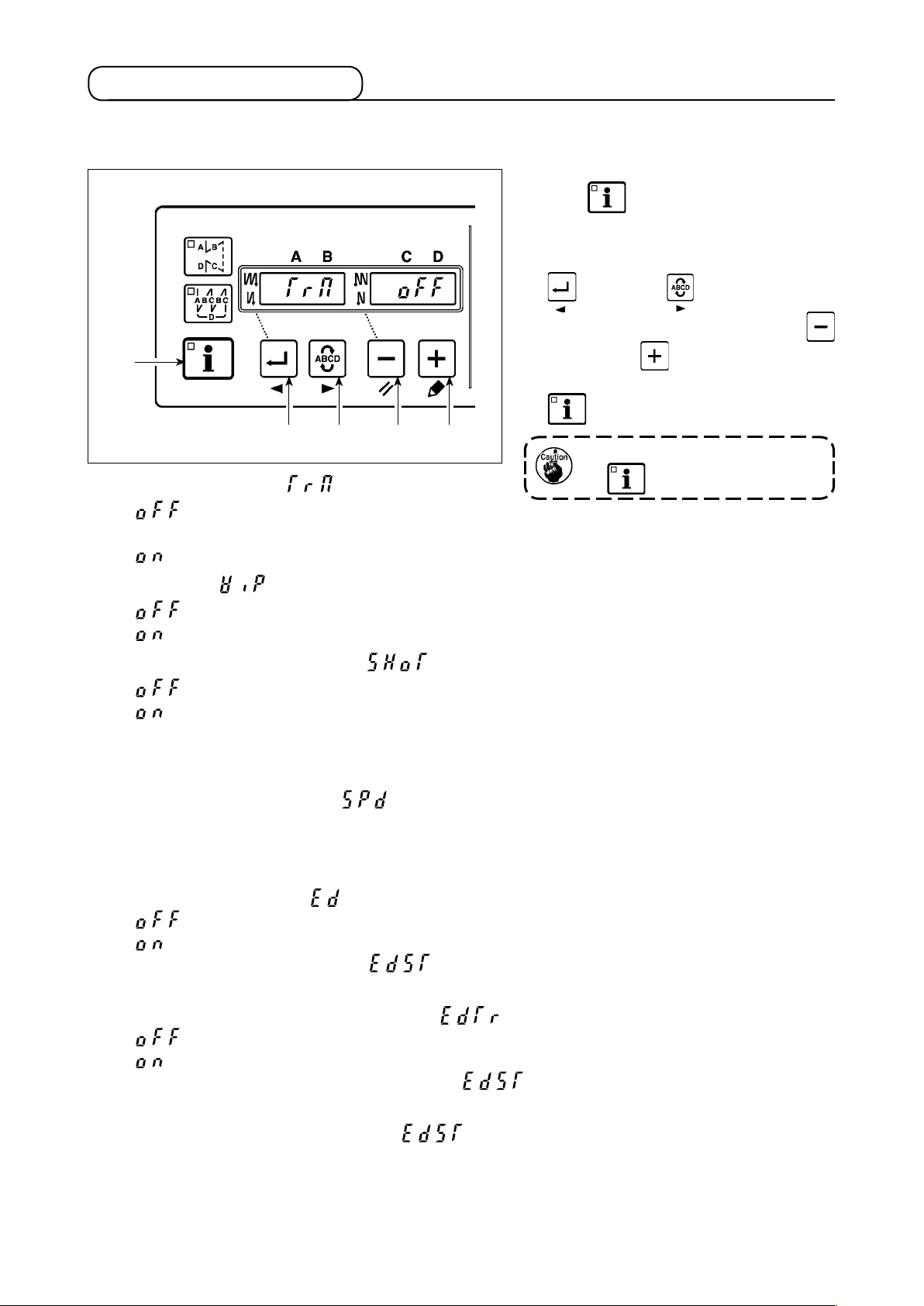
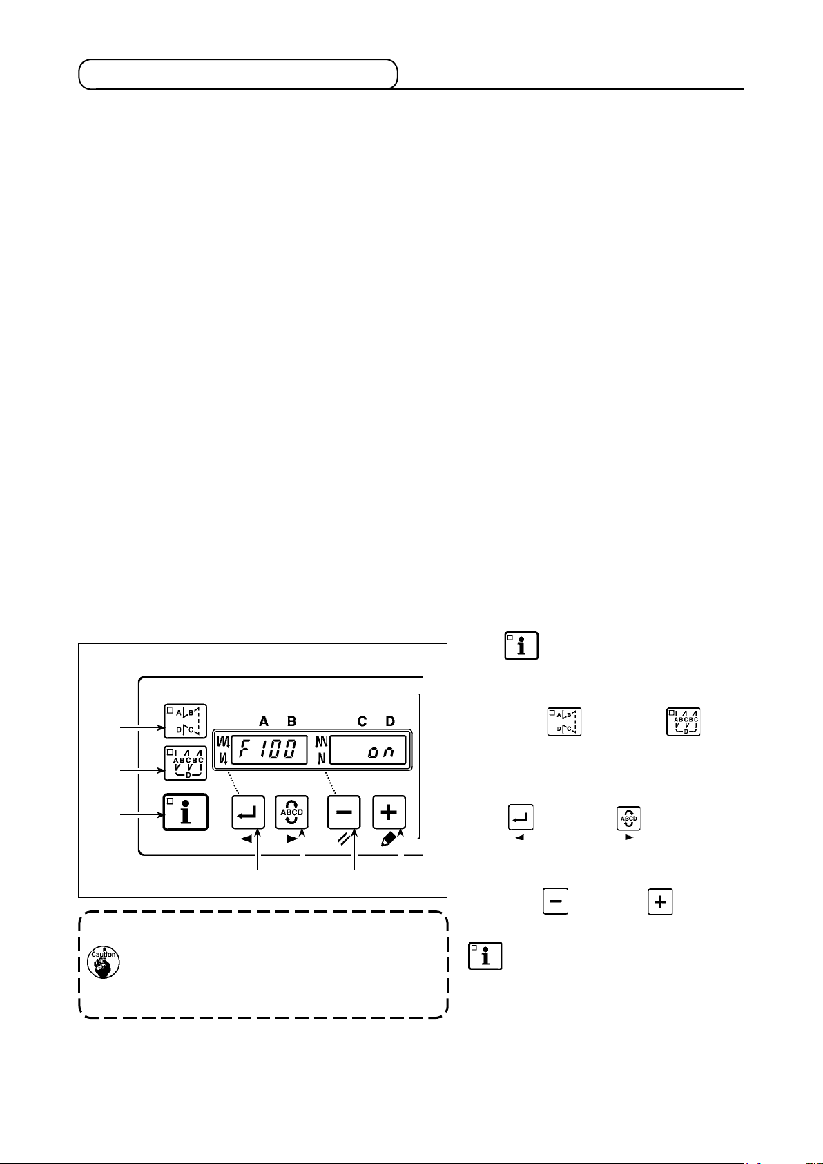
6-4. Productionsupportfunction........................................................................................................8
6-5. Settingoffunctions .................................................................................................................... 11
7. pROdUCTION MANAGEMENT dATA MEASUREMENT BLOCk (RIGHT
pANEL) .................................................................................................. 12
7-1. Conguration...............................................................................................................................12
7-2. Normalstartupmode ..................................................................................................................13
(1) Normal startup mode screen..................................................................................................... 14
(2) No. switch input procedure under normal startup mode ...........................................................15
(3) List of No. input patterns by switches........................................................................................16
(4) Outputting measurement data...................................................................................................17
(5) How to change over the shift.....................................................................................................17
7-3. Setupmode..................................................................................................................................18
(1) Setup mode screen ...................................................................................................................18
(2) MAC address check screen ...................................................................................................... 19
(3) Memory switch setup screen.....................................................................................................20
(4) Clock setup screen....................................................................................................................22
(5) Initialization screen....................................................................................................................23
(6) USB format screen.................................................................................................................... 24
(7) IP address setup screen............................................................................................................ 25
(8) Version check screen ................................................................................................................26
7-4. Softwarerewritemode................................................................................................................27
8. AUTOMATIC COMpENSATION Of NEUTRAL pOINT Of THE pEdAL
SENSOR ................................................................................................ 28
9. SELECTION Of THE pEdAL SpECIfICATIONS ................................ 28
10. SETTING Of THE AUTO LIfTER fUNCTION ..................................... 29
11. SELECTING pROCEdURE Of THE kEy-LOCk fUNCTION ............. 30
12. INITIALIzATION Of THE SETTING dATA ........................................... 30
13. ERROR INdICATION............................................................................. 31

– 1 –
ENGLISH
This Instruction Manual covers IT-10 Panel Indication.
Be sure to read "Safety precautions" in the Instruction for the SC-920 (control box) before reading this Instruction
Manual to fully understand them.
IT-10 comprises of 2 panels with different functions.
The left panel is used to set up the sewing pattern. For operation procedures, please see “6. SEwING pAT-
TERN SETUp BLOCk (LEfT pANEL)”.
The right panel is used to measure and set up the production management data. For operation procedures,
please see “7. pROdUCTION MANAGEMENT dATA MEASUREMENT BLOCk (RIGHT pANEL)”.
1. INTROdUCTION
Sewingpatternsetupblock Productionmanagementdatameasurementblock
Becarefulofhandlingthisproductsoasnottopourwateroroil,shockbydropping,andthelike
sincethisproductisaprecisioninstrument.
1
3
2
A
3 2 1
CN105
+5v
Sw
GNd
1
2
3
1) Press in the direction of arrow mark the click of
section Aof cord outlet cover 2assembled in
the rear of operation panel 1and remove the
cover.
2) Connect optional junction cable connector to
connector CN105 3of the count manual switch.
Note) Prepare the switch main unit by the
customersoraskJUKIbusinessoffice
aboutit.
OptionalrelaycableA(asm.)
JUKIPartNo.40008168
2. CONNECTING THE COUNT MANUAL SwITCH

– 2 –
5 6
3 4
1) Refer to "6-5. Setting for functions", and call
the function setting No. 95.
2) The type of machine head can be selected by
pressing switch
5
( switch
6
).
* Refer to the "MACHINE HEAd LIST" on the
separate sheet or the Instruction Manual for the
machine head of your sewing machine for the
type of the machine head.
3) After selecting the type of machine head, by
pressing switch 3( switch 4), the
step proceeds to 96 or 94, and the display auto-
matically changes to the contents of the setting
corresponding with the type of machine head.
4. SETTING pROCEdURE Of THE MACHINE HEAd
1Precautions to be taken when handling USB devices
• Do not leave the USB device or USB cable connected to the USB port while the sewing machine is in opera-
tion. The machine vibration can damage the port section resulting in loss of data stored on the USB device or
breakage of the USB device or sewing machine.
• Do not insert/remove a USB device during reading/writing a program or sewing data.
It may cause data breakage or malfunction.
• When the storage space of a USB device is partitioned, only one partition is accessible.
• Some type of the USB device may not be properly recognized by this sewing machine.
•
JUKI does not compensate for loss of data stored on the USB device caused by using it with this sewing machine.
2 USB specications
• Conform to USB 1.1 standard
• Format supported _____FAT 32
• Consumption current ___
The rated consumption current of the applicable USB devices is 500 mA at the maximum.
3. USB pORT

– 3 –
When the slip between the white marker dot on the handwheel and the concave of the cover is excessive
after thread trimming, adjust the angle of the machine head by the operation below.
1) Simultaneously pressing switch 4and
switch 5, turn ON the power switch.
2) is displayed (A) in the indicator and the
mode is changed over to the adjustment mode.
3) Turn the pulley of the machine head by hand un-
til the main-shaft reference signal is detected. At
this time, the degree of an angle from the main-
shaft reference signal is displayed on the indica-
tor B. (The value is the reference value.)
4) In this state, align the white dot 7of the hand-
wheel with the concave 8of the pulley cover as
shown in the gure.
5) Press switch 6to finish the adjustment
work. (The value is the reference value.)
5. AdjUSTING THE MACHINE HEAd
(dIRECT-dRIvE MOTOR TypE SEwING MACHINE ONLy)
7
8
4 5
A
B
6

– 4 –
6-1. Conguration
6. SEwING pATTERN SETUp BLOCk (LEfT pANEL)
1
C
2
D
7
3 4 5 6
E
AB
No. Buttonanddisplay Description
1switch : Used for changing over effective/ineffective of the reverse feed stitching
pattern.
2switch Used for changing over effective/ineffective of the overlapped stitching
pattern.
3switch Used for conrming the contents of setting and for changing over effec-
tive/ineffective of the reverse feed stitching at sewing start.
4switch
Used for selecting the process (A, B, C, D) the number of stitches for
which is to be changed.
* The selected process ashes on and off.
5switch :
Used for changing the content of the selected display (ashing section) and
for changing over effective/ineffective of the reverse stitch at sewing end.
6 switch Used for changing the content of the selected display (ashing section).
7 switch : Used for calling the production support function (by keeping the switch
held pressed for two seconds).
Indicators Aand B: Various pieces of information are displayed.
LED C: Lights up when the reverse feed stitching pattern is effective.
LED D: Lights up when the overlapped stitching pattern is effective.
LED E: Lights up when the production support function is displayed.

– 5 –
6-2. Operatingprocedureofthesewingpattern
Withoutreverse
stitching
Reverse
stitching
Doublereverse
stitching
(1)Reversefeedstitchingpattern
Reverse feed stitching at sewing start and reverse feed stitching at sewing end can be separately programmed.
[Settingprocedureofthereversefeedstitching]
1) Effective/ineffective of the reverse feed stitching
pattern can be changed over by pressing
switch 1.
When the reverse feed stitching pattern is ren-
dered effective, LED C lights up, the number of
stitches of the reverse feed stitching at sewing
start is displayed on A, and the number of stitch-
es of the reverse feed stitching at sewing end is
displayed on indicator B.
Select a process (A, B, C or D) the number of
stitches for which is to be changed by using
switch 4.
2) When the number of reverse feed stitches dis-
play is not flashing on and off, every press on
switch 3changes over the reverse feed
stitching mode from the "reverse feed stitching
at sewing start," "double reverse feed stitching
at sewing start" and "no reverse feed stitching at
sewing start."
In addition, every time switch 5is pressed,
the reverse feed stitching feature changes over
from the reverse feed stitching at sewing end to
the double reverse stitch at sewing end, then to
no reverse feed stitching at sewing end, in turn.
For some types of the machine head,
reverse feed stitching patterns are not
available.
The number which is ashing on and off represents the process which is being set.
Change the number of stitches for the selected process by using switch 5and switch 6.
Press switch 3 to conrm the
change you have made. (The number of stitches that can be set is 0 to 15.)
Thesewingmachinecannotperformsewingwhenthedisplayofthenumberofstitchesforapro-
cessisashingonandoff.
1
C
3 4 5 6
AB
3 5

– 6 –
A
B
C
B
C
d
2
D
3 4 5 6
A : Number of stitches of normal stitching setting
0 to 15 stitches
B : Number of stitches of reverse stitching setting
0 to 15 stitches
C : Number of stitches of normal stitching setting
0 to 15 stitches
D : Number of times of repetition
0 to 9 times
(Caution) WhenprocessDissetto5times,thesewingisrepeat-
edasA/B /C /B /C.
(2)Overlappedstitchingpattern
Overlapped stitching pattern can be programmed.
[Settingprocedureoftheoverlapped
stitching]
1) Effective/ineffective of the overlapped stitch-
ing pattern can be changed over by press-
ing switch 2.
When the overlapped stitching pattern is
rendered effective, LED Dlights up.
2) Select a process (A, B, C or D) the number
of stitches for which is to be changed by us-
ing switch 4.
The number which is flashing on and off
represents the process which is being set.
3) Change the number of stitches for the selected process by using switch 5and switch 6.
4) Press switch 3 to conrm the change you have made.
(The sewing machine does not run unless the setting has been conrmed by pressing switch 3.)
Theoverlappedstitchingpatterniscarriedoutunderautomaticoperationmode.Oncethepedal
isdepressed,thesewingmachinewillautomaticallyperformsewingofthenumberofoverlapped
stitches.

– 7 –
A part of function setting items can be easily changed in the normal sewing state.
6-3. One-touchsetting
[One-touchsettingprocedure]
1) Keep switch 7held pressed for one
second to place the panel in the function
setting mode.
2) Change over the item to be set by using
switch 3or switch 4. Then, the
set value can be changed by using
switch 5and switch 6.
3) To return to the normal sewing state, press
switch 7.
Thesettingisconrmedbypress-
ing switch7.
1Thread trimming function ( )
: Thread trimming operation is not performed (so-
lenoid output prohibition: Thread trimmer, wiper)
: Thread trimming operation is effective.
2Wiper function ( )
: Wiper does not operate after thread trimming
: Wiper operates after thread trimming
3One-shot automatic stitching function ( )
: One-shot automatic stitching function is ineffective.
: One-shot automatic stitching is effective.
※ Thisfunctionisrenderedeffectivewhenthematerialendsensorfunctionisset.Itisnotpossible
toprohibittheone-shotoperationduringoverlappedsewingoperation.Thenumberofrevolution
isthevaluewhichissetforsettingNo.38.
4Setting of the max. sewing speed ( )
The max. sewing speed of the machine head is set. The upper limit of the set value differs with the type of ma-
chine head to which the SC is connected.
Setting range : 150 - Max. value [sti/min]
5Material end sensor function ( )
: Material end sensor function is ineffective.
: Once the material end is detected, the sewing machine stops running after having sewn the num-
ber of stitches set with 7( ).
※ Thisfunctionisrenderedeffectivewhenthematerialendsensorfunctionisset.
6Thread trimming function by material end sensor ( )
: Automatic thread trimming function after the detection of material end is ineffective.
: Once the material end is detected, the sewing machine performs thread trimming after having
sewn the number of stitches set with 7( ).
※ Thisfunctionisrenderedeffectivewhenthematerialendsensorfunctionisset.
7Number of stitches for material end sensor ( )
The number of stitches to be sewn from the detection of material end to the stop of the sewing machine
Number of stitches that can be set: 0 to 19 (stitches)
※ Thisfunctionisrenderedeffectivewhenthematerialendsensorfunctionisset.
If the number of stitches specied is inadequate, the sewing machine can fail to stop within the
presetnumberofstitchesdependingonthenumberofrevolutionsofthesewingmachine.
7
3 4 5 6

– 8 –
[Tousetheproductionsupportmode]
Keep switch 7held pressed (one sec-
ond) in the normal sewing state to call the
one-touch setting screen.
Then, press switch 1or switch
2to set each production support mode in
ON/OFF state to call the one-touch setting
screen.
Press switch 3or switch 4to se-
lect the mode to be set in the ON/OFF state.
ON/OFF of the display can be changed over
by pressing switch 5or switch 6.
To return to the normal sewing state, press
switch 7.
ModesF100toF500havebeenfactory-setinthe
OFFstateatthetimeofdelivery.
The mode state is changed over to ON/OFF ac-
cordingtothesettingofthebobbinthreadcoun-
terfunction(functionsettingNo.6).
6-4. Productionsupportfunction
The production support function consists of three different functions (six different modes) such as the produc-
tion volume management function, operation measuring function and bobbin counter function. Each of them
has its own production support effect. Select the appropriate function (mode) as required.
■ Productionvolumemanagementfunction
Target No. of pcs. display mode [F100]
Target/actual No. of pcs difference display mode [F200]
The target number of pieces, actual number of pieces and the difference between the target and actual num-
ber of pieces along with the operation time are displayed to notify the operators of a delay and advance in real
time. Sewing machine operators are allowed to engage sewing while constantly checking his/her work pace.
This helps raise target awareness, thereby increasing productivity. In addition, a delay in work can be found at
an early stage to enable early detection of problems and early implementation of corrective measures.
■
Operationmeasuringfunction
Sewing machine availability rate display mode [F300]
Pitch time display mode [F400]
Average sawing speed display mode [F500]
Sewing machine availability status is automatically measured and displayed on the control panel. The data
obtained can be used as basic data to perform process analyses, line arrangement and equipment efciency
checkup.
■
Bobbincounterfunction
Bobbin counter display mode
In order to change bobbins before the current bobbin runs out of thread, the time for replacing the bobbin is no-
tied.
1
2
7
3 4 5 6

– 9 –
Sewing can be performed with the production support data displayed on the control panel.
[Basicoperationoftheproductionsupportmodes]
1) When switch 7is pressed in the nor-
mal sewing state, LED Elights up to enter
the production support mode.
2) Production support function can be changed
over by pressing switch 3or
switch 4.
3) Data attached marked with (*1) in Table 1
"Indicator A" can be changed by means of
switch 5and switch 6.
4) When you keep switch 6held pressed for two seconds, indicator Band LED E ash on and off. While
they are ashing on and off, data marked with (*2) in Table 1 "Display under modes" can be changed by press-
ing switch 5and switch 6.
When you press switch 7, the value marked with (*2) is conrmed and indicator Band LED Estop
ashing on and off.
5) The value with a sharp mark (*3) in Table 1 "Display of modes" can be changed only immediately after reset-
ting by using switch 5and switch 6.
6) Refer to the table "Mode resetting operation," for the resetting procedure of data.
7) To return to the normal sewing state, press switch 7.
Data to be displayed under the respective modes are as described in the table below.
Mode name Indicator AIndicator BIndicator B(when
switch 5is pressed)
Target No. of pcs. display
mode (F100)
Actual number of pieces
[Unit : piece]
(*1)
Target number of pieces
[Unit : piece]
(*2)
-
Target/actual No. of pcs.
difference display mode
(F200)
Difference between target
number of pieces and
actual number of pieces
[d : piece] (*1)
Target pitch time
[Unit : 100 msec] (*2)
-
Sewing machine availabili-
ty rate display mode (F300)
oP-r Sewing machine avail-
ability rate in the previous
sewing [Unit : %]
Display of average avail-
ability rate of sewing
machine [Unit : %]
Pitch time display mode
(F400)
Pi-T Pitch time in the previous
sewing [Unit : 1sec]
Display of average pitch
time [Unit : 100 msec]
Average sewing speed
display mode (F500)
ASPd Average sewing speed in
the previous sewing [Unit :
sti/min]
Display of average sew-
ing speed
[Unit : sti/min]
Bobbin counter display
mode
bbn Bobbin counter value (*3) -
Table1:Displayofmodes
7
3 4 5 6
E
AB

– 10 –
[Detailedsettingofproductionvolumemanagementfunction(F101,F102)]
When switch 7is held pressed (for three
seconds) under the target No. of pcs. display mode
(F100) or the target/actual No. of pcs. difference
display mode (F200), the detailed setting of the pro-
duction volume management function can be carried
out.
The setting state of the number of times of thread
trimming (F101) and that of the target achievement
buzzer (F102) can be changed over by pressing
switch 3or switch 4.
The number of times of thread trimming for sewing one piece of garment can be set by pressing switch
5or switch 6in the setting state of the number of times of thread trimming (F101).
It is possible to set whether the buzzer sounds or not when the actual number of pieces has reached the tar-
get volume by pressing switch 5or switch 6in the setting state of the target achievement buzzer
(F102).
Table2:Moderesettingoperation
Mode name Switch 5(held pressed for 2
seconds)
Switch 5(held pressed for 4 sec-
onds)
Target No. of pcs. display mode
(F100)
Resets the actual number of pieces
Resets the difference between tar-
get number of pieces and actual
number of pieces
-
Target/actual No. of pcs. differ-
ence display mode (F200)
Resets the actual number of pieces
Resets the difference between tar-
get number of pieces and actual
number of pieces
-
Sewing machine availability rate
display mode (F300)
Resets average availability rate of
sewing machine
Resets average availability rate of sew-
ing machine.
Resets average pitch time.
Resets average sewing speed of sew-
ing machine.
Pitch time display mode (F400) Resets average pitch time Resets average availability rate of sew-
ing machine.
Resets average pitch time.
Resets average sewing speed of sew-
ing machine.
Average sewing speed display
mode (F500)
Resets average sewing speed of
sewing machine.
Resets average availability rate of sew-
ing machine.
Resets average pitch time.
Resets average sewing speed of sew-
ing machine.
Bobbin counter display mode Resets the bobbin counter value
(Note that only the bobbin counter
is immediately reset by pressing
switch 5.)
-
7
3 4 5 6

– 11 –
Functions can be selected and specied.
※RefertotheInstructionManualforthecontrolboxfordetailsofthefunctionsetting.
1) Turn ON the power with switch 7held
pressed.
(The item which has been changed during the
previous work is displayed.)
* If the screen display does not change, re-carry
out operation described in step 1).
Besure tore-turnONthepower switch
whenoneormoresecondshavepassed
afterturningit OFF.If the powerswitch
is re-turned ON immediately after turn-
ingitOFF,thesewingmachinemayfail
to operate normally. In such a case, be
suretoturnONthepowerswitchagain
properly.
2) To move the setting No. forward, press
switch 4. To move the setting No. backward,
press switch 3.
IfthesettingNo.ismovedforward(or
backward), the previous (or subse-
quent)contentofthesettingiscon-
rmed.Becarefulwhenthecontentof
a setting is changed (when the /
switchistouched).
Example)
Changing the maximum number of revolutions
(setting No. 96)
Press switch 3or switch 4to call
setting No. "96."
The current set value is displayed on indicator B.
Press switch 5to change the setting to
"2500."
* The content of setting of the setting No. returns
to the initial value by pressing switch 5and
switch 6simultaneously.
3)
After completion of the changing procedure, press switch 3or switch 4 to conrm the updated value.
IfthepoweristurnedOFFbeforecarryingoutthisprocedure,thechangedcontentisnotupdated.
When switch 3 is pressed, the display on the panel changes to the previous setting No.
When switch4ispressed,thedisplayonthepanelchangestothesubsequentsettingNo.
Aftercompletionoftheoperation,themachineisreturnedtothenormalsewingstatebyturning
OFFthepowerandre-turningitON.
6-5. Settingoffunctions
7
3 4 5 6
3 4 5 6
B

– 12 –
7-1. Conguration
7. pROdUCTION MANAGEMENT dATA MEASUREMENT BLOCk
(RIGHT pANEL)
1
A
4
C
2
D E F
3
B
G
No. Switch/indication Description
AClock LED Lights up when the clock is displayed.
B7-segment indication block Indicates various ID data and clock information.
CProduct No. LED Lights up when Product No. ID is displayed on B.
→ See “7-2.(1)Normalstartupmodescreen”.
DOperator ID LED Lights up when Operator ID is displayed on B.
→ See “7-2.(1)Normalstartupmodescreen”.
EOptional ID LED Lights up when Optional ID is displayed on B.
→ See “7-2.(1)Normalstartupmodescreen”.
FTransmitted data LED Lights up when Transmitted data is displayed on B.
→ See “7-2.(1)Normalstartupmodescreen”.
GNo. LED The selected No. will light up.
1switch The value to be indicated in Bis set up here. The value in-
creases when this switch is pressed.
2switch The value to be indicated in Bis set up here. The value de-
creases when this switch is pressed.
3switch
The item to be indicated in Bis changed here. The indicated
item changes when this switch is pressed.
→ See“7-2.Normalstartupmode”.
4No. switch Setup information (ID) registered for each item is selected here.

– 13 –
7-2. Normalstartupmode
1
2
When the power supply is turned on, the item screen
and ID data which had been selected before it was
turned off in the previous operation.
The selected item and the number for which the ID is
registered are indicated in LED.
When the No. switch 1is pressed, the ID data for
the selected No. is indicated.
When the switch 2is pressed the following
item screen is displayed.

– 14 –
(1)Normalstartupmodescreen
■ProductNo.displayscreen
The 16-digit Product No. ID is indicated.
A registered ID can be set up from the No.
switch.
Press the switch is pressed.
■Clockindication
The current clock is indicated.
■OperatorIDdisplayscreen
The 8-digit operator ID is indicated.
A registered ID can be set up from the No.
switch.
Press the switch is pressed.
■OptionalIDdisplayscreen
The 8-digit optional ID is indicated.
A registered ID can be set up from the
No. switch.
Press the switch is pressed.
■Transmissiondisplayscreen
Up to 16 digits of the transmission
data is indicated. A registered ID can
be set up from the No. switch.
Press
the
switch is
pressed.
Press the switch is pressed.
After 3 seconds
After 3 seconds
After 3 seconds
After 3 seconds
Press the
switch is
pressed.
Press the switch is
pressed.
Press the switch is pressed.

– 15 –
IDisindicatedsuccessivelyfromtherst4digits.
IftheID is 1234 56789ABCDEFG,it is indicatedasfollowsand the indicationswitchestothe
clockwhentheentireIDisindicated.
After1.5seconds After1.5seconds
Clockindication
After3seconds
After1.5seconds
(2)No.switchinputprocedureundernormalstartupmode
When the 2 out of the 1 to 5 No. switches are pressed successively, ID can be selected from 30 different IDs.
It is considered one-switch operation if one No. switch is pressed and the switch or another switch is not
pressed within 1 second and two-switch operation if the next switch is pressed within 1 second.
* For one-switch operation, the corresponding No. LED lights up. For two-switch operation, the rst No. LED
lights up and the second No. LED blinks.
<e.g.>Inputting“3”(one-switchoperation)
is pressed. ( lights up).
→ No. switch is input successively for 1 second or lon-
ger.
<e.g.>Inputting“25”(two-switchoperation)
Whethertheclockisautomaticallydisplayedafter3secondsorbypressingthe switchcan
beselectedusingthememoryswitch.
Whenthesettingtodisplaytheclockwiththe switchisselected,theselectedIDisindicat-
edbypressingthememoryswitch.
is pressed. ( lights up).
→Then is pressed successively within 1
second ( blinks).

– 16 –
(3)ListofNo.inputpatternsbyswitches
No. First switch
input
Second switch
input No. First switch
input
Second
switch input
1 After 1 second 16
2 After 1 second 17
3 After 1 second 18
4 After 1 second 19
5 After 1 second 20
6 21
7 22
8 23
9 24
10 25
11 26
12 27
13 28
14 29
15 30
indication : Lights up. indication : Blinks.
WhenNo.30(switches + )isinput,IDwillbeunselected.

– 17 –
1
2
When switch 1is pressed for one second or
longer under normal mode, USB data writing func-
tion is enabled. When switch 2is pressed for
one second or longer, network data transmission
function is enabled.
“Wait” blinks on the 7-segment indication block dur-
ing data output.
(4)Outputtingmeasurementdata
In transmission data indication under normal mode, it is possible to indicate 30 different data
dependingontheNo.switchinputcombinationandchecktheIPaddressinasimilarfashionto
otherIDdataindication.
ThesewingmachineIDcanbecheckedbyNo.29(switches + )fortransmissiondata,
andtheIPaddressbyNo.30(switches + ).
e.g.ForIPaddress192.168.1.106,
1stblock
After1.5seconds
2ndblock
After1.5seconds
3rdblock
After3seconds
4thblock
After1.5seconds
Clockindication
(5)Howtochangeovertheshift
1
2
3
Shift number can be changed over by turning the
power on with switch 3held pressed.
Select the desired shift number by means of
switch 1or switch 2.
0 : No shift number
1-3 : Select the shift number set in 1A-1.
Refer to HELP for 1A-1 for details of the shift.

– 18 –
Press
the
switch.
Press the
switch.
Press
the
switch.
■
MACaddresscheckscreen
MAC address assigned for each
system can be checked. →See
“7-3.(2)MACaddresscheckscreen.”
■ Initializationscreen
Panel data initialization is execut-
ed. →See “
7-3
.(5)Initialization
screen.”
Press the
switch. Press the
switch.
Press the
switch. Press the
switch.
■
Setupscreen ■
Memoryswitchsetupscreen
The memory switch No. is set up.
→See “
7-3
. (3) Memory switch
setupscreen.”
■ USBformatscreen
The medium connected to USB is
formatted. →See “
7-3
. (6) USB
formatscreen.”
Press the
switch. Press the
switch.
Press the
switch. Press the
switch.
■ Clocksetupscreen
The clock is set up. →See “
7-3
.
(4)Clocksetupscreen.”
■
IPaddresscheckscreen
The procedure to obtain the IP
address is selected. →See “
7-3
.
(7)IPaddresssetupscreen.”
Press the
switch. Press the
switch.
*Ifthisscreenappears,turnthepower
OFFandre-turnitON.
■ Versioncheckscreen
The panel version is checked.
→
See “
7-3
.(8)Versioncheckscreen.
”
7-3. Setupmode
(1)Setupmodescreen
When the power supply is turned on with switch pressed, the system starts up in setup
mode.
In setup mode, the setting
item i s selected by using
and switches and
conrmed by using the
switch. When confirmed, the
corresponding setup screen
will be displayed.
After the completion of the
setting procedure, turn the
power OFF and re-turn it ON.
Press the switch.
Press
the
switch.
Press the switch.
Table of contents
Other JUKI Sewing Machine manuals

JUKI
JUKI LU-1520N-7 User manual

JUKI
JUKI AMS-210EN/IP-420 User manual

JUKI
JUKI HZL-F series User manual

JUKI
JUKI DDL-5550N-7 User manual

JUKI
JUKI AMS-224EN/IP-420 User manual

JUKI
JUKI 812K Setup guide

JUKI
JUKI UnionSpecial 35800BLW Setup guide

JUKI
JUKI LK-1910 User manual

JUKI
JUKI HZL-35Z User manual

JUKI
JUKI LS-1340 User manual

JUKI
JUKI LZ-2280N Series User manual

JUKI
JUKI LU-562 User manual

JUKI
JUKI MO-6704D User manual

JUKI
JUKI PS-800-12080 User manual

JUKI
JUKI DSC-244 User manual

JUKI
JUKI LU-1520NCS-7 User manual

JUKI
JUKI TL-2200QVP Mini User manual

JUKI
JUKI LK-1850 Series User manual

JUKI
JUKI APW-895/IP-420 User manual

JUKI
JUKI DDL-9000C-S Series User manual