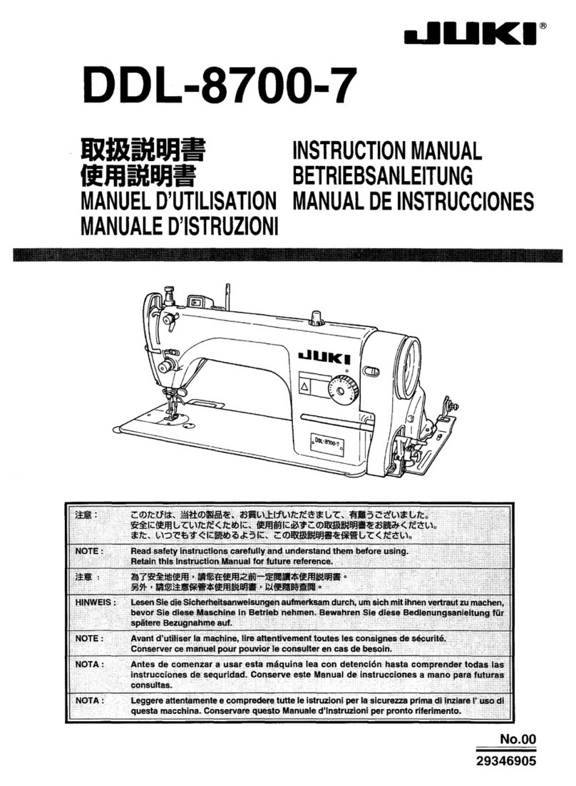
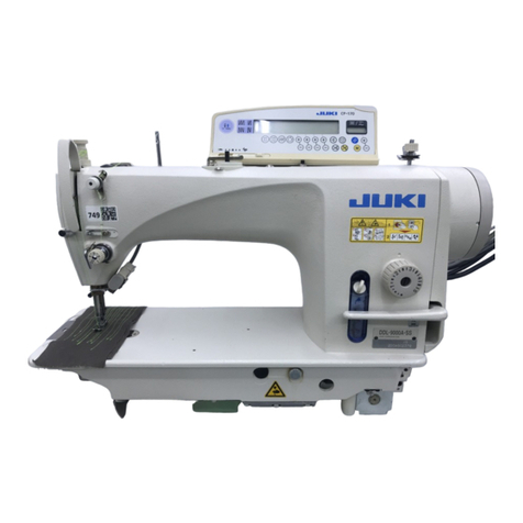
JUKI MO-2404 User manual

8E240430tsoA No.04
MODEL
MO.24O4
l.NEEDLE
OVEREDGER
MODEL
MO-241 4
2.NEEDLE
OVEREDGER
MODEL
MO -241 6
SAFETY
STITCHER
InsrnucTtoN
Congratulations on' your purchase of JUKI
MO-2400Seriesmachines.
Pleasereadthis Instruction Book carefullybefore
usingtheseunits in order to get the mostout of
them andto enjoy usingthem for a longtime.
[For ttre first one month or so,operatethe I
lmachine at about 80% speedof its max. I
[sewing
speed. J
BEFORE
OPERATION
Cloth plate cover
1. Do not hold the cloth platecoverwhen carrying
the
machine.
3. Apply two or threedropsof oil to the needlebar guideand upper
looper
guide
whenoperating
the machinefor the first timeaftersetup
or afteralong
period
of disuse.
A"iewed
from
toP) oir
sause
sz f&
2. lf the red color is'not seenwhenyou look down or
sideward
at the oil gauge,
supplyoil in accordancewith
"6. Lubrication".
Runningdirection
4. Thecorrectmachinerunningdirection
is
suchthatthehandwheel
turnsclock-
wise asviewed
from the handwheel's
side. Never run the machinein the
reverse
direction.
CAUTIONSIN OPERATION
1. Do not put your handunderthe
needle whijn you turn on the
power
switch.
4. Neverbring
your
fingers
orhair
closeto,or place
anything
on the handwheel,
V-belt,bobbin
winderwheelor motor
duringoperation.
lt maylead
to serious
personal
injuries.
5. lf your
machineis
provided
withabeltcover,finger
guard
and eyeguard,
neveroperate
your machine
with anyof
themremoved.
2. Do not put your handintothe
face plate section while the
machineis
running.
3. Be sure to turn off the power
switch beforeyou removethe V
belt.
-l-

* Semi-sunken
type
8-o
e- o
_e-
_o
I Attach blo*'er case @ , rubber cushion
@ . rubber
cushion
seat @ , nut €) , case
presser plate @.
and case sponge
@ to frame support plate Q .
3. Install upper waste chute @ to the left on the table,
and then attach lower waste chute @ to the upper
wastechute.
The installation of the chutes can be adiusted within
a length
of 56 mm.
1. Attach frame support plate joint
€), blu.rr'e.case€). ru-
bber cushronO.
rubber cushion
seat O. case
presser
plate
@, andcase sp,,nge
@ to frame
support plate (D.
* Fully-sunkentype
8-O
g-o
-o
3. Attachwaste
chute @ to frame
support
plate
O
s
gg
os .,e
O s,tV)
V// g
m \.!./ 9
gv
r.->:
-.4 e
c-l
(9
Table
I
2. Installframe
support
plate O directly
to thetable Install framesupport plate Q sothat the cloth plate
is 5 mm higher
than the surface
of the machine
table.
-2-

Sewingspeed
(s.p.m.)
50
Hz 60
Hz
Motor
pulley
Outer
dia.
(mm)
V belt (inch) Motor pulley
Outer dia.
(mm)
(V belt (inch)
Semi-sunken
type Fully-sunken
type Semi-sunken
type Fully-sunken
type
6500 r20.5 38 32 t00.5 36 32
6000 110.s 36 32 95.5 35 30
5500 r
00.5 Jt) )z 85.5 J5 30
s000 90.5 35 30 80.s 5.1 30
4500 85.s 35 30 70.5 34 30
Install
belt cover
Q to the machinehead.
l Use a 400W (1/2 tP) clutch
motor.
2. UseaMtypeVbelt.
3. The table on the left shows
the sewing speedsobtained
by the use of motor pulleys
with different diameters
and
V belts
with different lengths.
4. Note that the effective dia-
meter of the machine head
pulley has been changed to
50 mm.
4. INSTALLING
THE PEDALS
l. Install startingpedal Q on the left andpresser
lifter pedal
O on
the right asseenfrom the operator.
2. Usean S-shaped
hook O to connect the chain@ of the presser
lifter pedal to presser
lifting lever @ .
t 651t3"'NG
rHEBELr
5. SETTING
UP THE THREAD
STAND
Standard
thread
soool Assemble the thread stand
components
asillustrated
and
setit up on the machinetable
(The figure on the left shows
an assembled
5-thread stand
for Model MO-2416.)
-3-

l.
2.
3.
Removeoil cap() .
PourJUKI New Defrix Oil No.2 into the oil reservoir.
Stop supplyingthe oil when the red color hasfully spread
as
you
look down at oil gauge@ or when the red color has
reachedthe
red lineas
you look sidewards
at the oil gauge.
Removeoil drain cap @ when drawingthe oil reservou.
* Lubricating
theneedle
color
l. Open looper coverO , tltt the needle
cooler
with
silicone oil through 6 , using the furnished oil
feeder.
2. Infiltrate silicone orl also into the oil fett if the
machineis started
immediately after lubricating
the
needlecooler.
7. OP
EN
ING
/CLOS
ING THECOVER * Cloth plate
cover
To open cloth plate cover O , push down
cloth plate opening lever O To close the
cover,
push
it in the arrowed
direction.
* Looper
cover
To open looper cover @ , move the looper
coverin the arrowed direction until it will go
back no farther,then bring it down.
Raise
the looper coverwhen closing
it.
* Chip guard cover(upper)
If the
chip
guard
cover
ofteninterferes
with
the
upperlooper.installchip
guarrl
covet'
upper
)@.
(Caution)
For a fully-sunken table type, make sure to
lower waste chute opening @ before opening
the looper cover.
8. ATTACHING
A NEEDLE
The standardneedleis DC x 27 #1 1. A needleof DC x I canbe also
used,
but it sometimesrequiresadjustmentof the clearance
between
the looperand needle.
It isadvisable
to usea needleof DC x2'7 for strict stitch performance.
1. Bring needleclamp O to the highest
position.
2. Loosenneedleclamp screw @ ,and fully insertthe needleinto the needleclamphole with the needlerecessfacing
backwards
asviewedfrom the operator'sside.
3. Tightenthe needleclamp
screw.
MO-2404 MO-24t
4MO-24 |
6
-4-

9. THREADING
THE MACHINE
Threadthe machineaccordingto the threadingchart
given
below.(The samechdrt
is on the inside
of the looper cover.)
MO-2404
MO-24 | 6
MO-24t 4
Important :
Lnri-z414:l
ffi:
(,trru+)
W/
Be sure to pass the double-chain stitch needle
thread through the needle thread take-up.
(The outer thread is
the overlck needlethread.)
(Gautionl
Whenusingan untwistedthread
such
aswooly nylon
threador weak
thread,
do not wind it roundthe intermediate
thread
guide.
-)-
Intermediate
thread
guide

MO-2404 MO-2414
Using
the thread tension nut, adjustto anoptimum thread
tensionaccordingto your sewingconditionssuchastype of materials,
type andsizeof thread,
etc.
11. PRESSER
FOOT
PRESSURE
ANDLIFTER
MO-2404
Adjust the pressure of the presserfoot by turning
presser
foot adjust
screw
O .When
the adjustscrew
is turned clockwise,the pressure
increases,
while the
pressure
decreaseswhen the screwisturned counter-
clockwise.
When you turn presser
foot assemblyO side-ways,
bring down presserlifting lever @ . Whenever the
presser
foot is returned to its original position, be
sureto bring up the presser
lifting lever.
MO-24t4.MO-24tb MO-24t6
1. Slowly turn the handwheel
as
you keepdepressing
pushbutton O ,
and you will find a point at which the pushbuttongoes
in farther.
2. With the above condition maintained, align a desired
dial on the
handwheelwith white mark O on the belt cover.
3. Reset
the pushbutton after settingthe dial.
tt. fro*r3f,IrNG
rHE
silrcH
MO-24
t6
13. DIFFERENTIAL
FEED
MECHANISM
l. Loosen differential feed lock nut O . Turn leverO up for
stretchingstitch or down for gathering
stitch.
2. Position "S" is for stretching stitch of a ratio of l:0.7 and
position "0" provides
a differentialfeedrrtio of 1:1.
3. Gathering stitch can be madeup to a differential feed ratio of
1:2 (possible
up to l:4 by adjusting
the internalmechanism).
The divisionsbevond "0" mav be used
asa measure.
-6-

Whenthe needlebar is at the highest
point of its stroke, the pointed end of the overedging
needle
should
be l0 mm above
the
throat olatesurface.
MO-24
14 til|
] (Stanoaro
teft
settins) \/\/ I
MO-2404
10
mm Throat plate Throat plate
15. SETTING
THE LOOPERS
Go back
farthest * Lowerlooper
l. When lower looper Q has gone back
farthest, it should be distanced 3.7 to
4.3 mm from overedgingneedle
O .
2. When the lower looper is crossedwith the
needle,
the clearance
between
them should
be
0.05to 0.1mm.
3. To make adjustment, loosen setscrew O
and movelower looper holder O .
* Upperlooper
1. When
upper looper @ has
advancedfarthest,
it shouldbedistanced
10.4
to 11.0mm from the overedging
needle
for MO-2414,
and
10.7
to 11.3
mm for MO-2404
and MO-2416.
2. The clearance
betweenupper looper O and lower looper O when
they are
crossedeach
other should
be 0.05 to 0.2 mm.
3. To make adjustment, loosen setscrew @ and move the upper
looper.
* Usea properupperlooperaccording
to the count of the needle
used
in accordancewith the table shown below. When placing orders,
specify
the bracketed
numbers[--l
.
Model Numeralsengravedon
upper looper Countof Needle
1-Needle
Overedger
Safety Stitcher
88@ #8
- #13(#14)
88m #14
- #20
(#13)
I888
2-NeedleOveredger I888 #6 - #8(#9\
88 l8al #9- #16
* Avoidusingneedles
withthebracketed
countsas
muchas
possible.
Go back
farthest *
1Double-chain
looper
0.05
- 0.1mm When double-chain looper O has gone
back farthest, it should be distancel 8 to
2 mm from double-chainneedle
@ .
The clearancebetween the double-chain
looper and needle should be 0.05 to
0.1 mm when they arecrossedeachother.
To perform the adjustment, loosen set-
screw (E and move double-chainlooper
holder O .
2.
o
-4
It-
tl
\1
1J.t
lio
t/
-]._1.8-2mm
3mm 0.05
- 0.1
mm
--\-, rl
\\\r-u
"lm\
ry/'
--\+r\\
\\\----o
"-A
ry
L
MO-2404
MO_2416 _ ru./
MO-2414 - 10.4
- 11.3mm
- 11.0
mm
0.05
- 0.2
mm
-'7 -

0.8mm O.5mm
Ihroat
pl
ate
* Heightof feed
dog
1. Feeddog O is usuallysetso that its teeth protrude about
0.8 mm from the throat plate
surfaceat the highest
point in
its trajectory. Increase the protrusion for heavy-weight
materials
or reduceit for light-weight
materials.
2. Use setscrew O to adjustthe protrusion of the feed dog
teeth.
3. Using setscrew O , make adjustment so that differential
feeddog @ islevel
with the main feed
dog.
4. Adjust the height of auxiliary feed dog O by setscrew
@
sothat it is 0.5 mm lower than the main feed
doe.
* Contact of the presser
foot with the throat plate
top surface
Usirrg
adjust screw @ , perform adjustmentsothat the soleof
the presser
foot evenly comesin contact with the top surface
of the throat platewhen presser
foot O comesdown.
|?).*=il)1
* Inclination
of feeddog
1. Loosen screw O , and turn eccentric shaft O in the
arrowed direction to make the feed dog front up or turn it
in the reverse
directionto setthe feed
dogfront down.
2. The feed dog should be levelled
when the dot engraved
on
the eccentric
shaftfaces
exactlvto the ieft.
i
o
Front
up
17. CHAIN LOOPERTHREAD
CAM(MO-2416)
Loosensetscrew
@ , andadjust
chainlooperthreadcam
O so
that 6 of the chain looper thread cam meets
the bottom of
looper thread cam pawl O when the needle
is at its highest
position. Make surethat the chain looper thread cam releases
the looper thread at the moment the needle
point startsto go
below the bottom of the throat plate
underthis condition.
. || Overedge
'"'""Kf*
Throat
plate
18. THREAD
GUIDE
AND LOOPERTHREADTAKE.UP
The tablebelow showsthe standarddemensionsof the individ-
ual thread guides
and looper thread take-upswhen the upper
looperhas
gone
backfarthest.
3ode MO-2404
MO-2416
(Standard) MO-2414
(Standard) MO-2405
(Hemming
bottom)- MO-2404
(Softchain)
GwGwGwGw
74 79.5
B74 79
C22.5
D63
.5
E40.5
F26
C37
.5 45 45 37.5 45 4l 7
Ht2 IJ 18.5 9.5 t2 l3 26.5
6.5 24.5 33.5 2E.0 33.5
J23 I
K
L74
M63
l
-8- G : Generalthread W : Wooly thread (Unit
:mm)

* Heightof thelower
knife
Loosensetscrew
€) andadjustthe heightof lower knife O so
that its edgeis
flush with the throat plate
surface.
* Heightof theupper
knife
Loosensetscrews
O , O and
perform adjustment
so
that upper
knife @ overlapslower knife O by 0.5 to I mm whenthe
upperknife isat its lowert point.
* Overedge
width
Overedge
widths of 1.6 thrqugh 6.4 mm are provided
by
changing
the partsor by using
subclassmodels.
(The overedge
width will be slightlylargerthan the knife cut width.)
To change
theoveredgewidthl
l. Loosening
setscrew
@ , push
lower knife O to the left and
fix it.
2. Loosensetscrew
@ and move upper knife @ as
required,
then
fix it.
3. Lower the upper knife to its lowest point and loosenset-
screw @ . Tightensetscrew
@ whenthe lower knife comes
in contact with the upperknife.
(Caution) Be sure to tighten screw G) before operating
machine.
* Resharpening
thelowerknife
When the lower knife hasbecomedull, resharpen
it as
shown
in the figureleft.
20. NEEDLEGUARD
* For
1-Needle
and2-NeedleOveredgers
An overedgerisequippedwith two needleguards
O and O .
1. Positionneedle
guard O sothat it lightly comesin contact
with needle
O when the blade
point of lower looper O has
reachedthe center
of needle
O .
2. Position needle
guard O so that it is 1 mm lower than the
bottom surfaceof the throat piate
endisdistanced0.1 mm
from needle
O when the needleis at its lowestpoint.
* Forsafety
stitchers
A safetystitcherhasfour needle
guards O , O , @ andO .
1. Position needle
guards
tl) and O in the samemanner
asthe
overedgerexplained
above.
2. Position needle
guard O sothat it lightly comes
in contact
with needleO , and position needle
guard@ sothat it is
distanced0.1 mm from needle@when the needle
is at its
iowestpoint.
i
-9 -

STITCH
FAILURE CAUSES CORRECTIVE
MEASURES
1. Needle
breaking (l) Needletypelswrong.
(2) Needlecount isnot correct.
(3) Needleis not installed correctly.
(4) Needleisnot straight.
(5) Needle-to-needle
guard
isinadequate.
(6) Needle-to-looper
relationisinadequate.
o Usea specifiedneedle.
o Usea needlesize
suitable to the thread gauge
and type of fabrics.
o Install
the needle
in the correct
way (See
8).
o Usea straight needle.
o Correct
the relation
(See
20).
o Correct
theneedle
to looperrelation(See15).
2. Cloth
is
notcut (I) Position of the upper and lower knife is
inadequate.
(2) Knife blade
hasworn out.
o Adjust the knife position(
See
1
9).
o Sharpenthe lower knife or renew the upper
knife.
3. Stitchskipping (l)
(2)
(3)
(4)
(s)
Needle-to-looperrelation is wrong.
Looper bladeisblunt.
Needleisthreaded
with S-twist
(or left-
handtwist) thread.
Threadtension
iswrong.
Double chainlooper thread
tensionisnot
enough.
o Correctthe needle-toJooper
relation
(See
15).
o Correctthe shapeof the looperbladeusing
an oilstone,or replace
it.
o Usea Z-twist (or right-hand
twist) threadwith
the needle.
o Adjust the t\read tension
(See
l0).
o Correctthe positionof the chainlooperthreac
cam
(See
l7).
4. Thread breaking (
1) Quality of the thread
ispoor.
(2) Thread
istoo thick for the needlesize.
(3) Needleisinstalledin a wrong way.
(4) Thread
tensionistoo high.
(5) Thereisa scratchor bruiseon the surface
of needle,looper,throat plateor needle
suard.
o Usea thread of good quality.
o Selecta suitableneedleor thread.
o Installthe needlecorrectly
(See
8).
o Adjust the thread
tension
(See
10).
o Remove
scratchesand bruises
usinganoil-
stone or buffing machine.
5. Double chain-off
thread stitching
arenot correct.
(MO-2416)
(I) Presserfoot doesnot evenly act on the feed
dog.
(2) Rear
presser
isshaking.
(3) Needle
threadand looper threadtensions
arenot correct.
(4) Double chain
looperisinstalled
in a wrong
wav
o Correctthe relationof the presser
foot with
the feeddog.(SeeI6).
o Adjust the rear presser.
for smooth and
steadymotion.
o Adjust
thethread
tension
(See
l0).
o Correctthe doublechain
looper(see
I 5).
6. Puckering (
I) Needleis
too thick.
(2) Tiread tension
istoo high.
(3) Pressure
appliedby the presser
foot istoo
highor too low.
(4) Feeddog comes
up too niuch from the
throat plate
surface.
(5) Knife failsto cut the fabrics
sharply.
(6) Differential feedmechanismis not set
correctly.
o Select
asuitable
needlesizefor the thread
and materials.
Adjust the thread
tension.
Correct
the presser
foot pressure
(See I 1).
Lower the feeddog.
Sharpenthe lower knife.
Correct
the differentialfeedmechanism
(See
13).
o
o
o
o
o
Irregular stitching (I) Thread is not supplied smoothly
(2) Thread
tension
istoo low.
(3) Needleis
blunt.
(4) Pressureappliedby the presser
foot is
inadequate.
(
5) Heightof the feeddogiswrong.
Usesmooth thread
with eventhicknessor
cleanup thethread
path.
Increase
the threadtension.
Useanew needle.
Adjust the presser
foot pressure
(See I l).
Adjust the heightof the feeddog(See
I6)
o
o
o
22. SPECIFICATIONS
MO-2404 MO-2414 MO-2416
Sewingspeed
(Max.) 6500
s.p.m. 6500
s.p.m. 6500
s.p.m.
Stitch length 0.8
- 4 mm(1164"
- 5132")
(special
model
:up
to 5mm) 1.5-4mm(5mm)
Needle
gauge 1.6,2.0,2.4
mm 1.6,
2.0,
2.4,
3.2,4.8,6.8mn
Overedgewidth r.6,
2.4,3.2,4.O,4.8,
6.4mm 2.0.3.2.4.0.4.8
mm 3.2,
4.0,
4.8,5.6,6.4
mm
Differential feed ratio Gatheringstitch
l:2 (Max.
l:4) Stretchingstitch
l:0.7
(Max.
l:0.6)
Needle DC x 27 (standard) (DC x I may be used)
Presser
foot lift Max. 7.0 mm\9 132")(excluding
somesubclassmodels)
Lubricating
oil JUKINew
DefrixOilNo.
2
-10-
(
iln:,l:,rl#'ii'fJT,ffi:i,:H$i:x't*ff
f:' "
)
rl I||llY||
JUlfi
Iil[U$In|l|.
80..[10.
I f Head
Office& Plant:2-1,
8-chome,
Kokuryo-cho,Chofu-shi,
Tokyo, Japan
I I BusinessOffice: 23-3,Kabuki-cho
1-chome,Shiniuku-ku,
Tokyo 160,Japan
- cabte:JUK| ToKYo retex:22967:2g2-2301
Phone:03(205)1
1
88,
1189,
1190
Appearanceandspecificationlisted
inthiscatalogare
subjectedto change
without notice.
1981.'7
Printedin Japan(11)
This manual suits for next models
2
Table of contents
Other JUKI Sewing Machine manuals

JUKI
JUKI DLN-9010A User manual

JUKI
JUKI LK-1903BN/BR35 User manual

JUKI
JUKI SC-510 Quick start guide

JUKI
JUKI MO-644DN User manual

JUKI
JUKI PS-800-12080 User manual

JUKI
JUKI DDL-8700A-7 User manual

JUKI
JUKI DDL 552 User manual

JUKI
JUKI LBH-1790S User manual

JUKI
JUKI HZL - 353Z Series User manual

JUKI
JUKI LZ-2290A-SR/IP-100D/SC-916 User manual

JUKI
JUKI PLK-G4030R User manual

JUKI
JUKI LS-1340 User manual

JUKI
JUKI MF-7700D Series Quick start guide

JUKI
JUKI TL-2010Q User manual

JUKI
JUKI SC-910 Quick start guide

JUKI
JUKI TC16 User manual

JUKI
JUKI HZL-70HW-B User manual

JUKI
JUKI UnionSpecial 35800BLWG Setup guide

JUKI
JUKI CP-160 User manual

JUKI
JUKI LBH-781 User manual